1996 CHRYSLER VOYAGER hood release
[x] Cancel search: hood releasePage 1281 of 1938
FRAME AND BUMPERS
CONTENTS
page page
BUMPERS AND FASCIA.................... 1FRAME................................. 3
BUMPERS AND FASCIA
INDEX
page page
REMOVAL AND INSTALLATION
FRONT BUMPER FASCIA.................. 1
FRONT BUMPER REINFORCEMENT.......... 1REAR BUMPER FASCIA................... 2
REAR BUMPER REINFORCEMENT........... 2
REMOVAL AND INSTALLATION
FRONT BUMPER FASCIA
REMOVAL
(1) Release hood latch and open hood.
(2) Remove bolts holding fascia to headlamp
mounting panel at each side of grille.
(3) Hoist and support vehicle on safety stands.
(4) Remove front wheels. Refer to Group 22,
Wheels and Tires, for proper procedures and
sequence.
(5) Remove front wheelhouse splash shields fasten-
ers as necessary to gain access to bolts holding front
fascia to fender. Refer to Group 23, Body, for proper
procedures.
(6) Remove bolts holding fascia to bottom of front
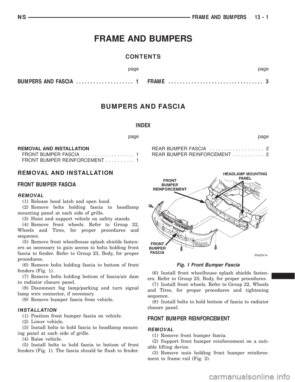
fenders (Fig. 1).
(7) Remove bolts holding bottom of fascia/air dam
to radiator closure panel.
(8) Disconnect fog lamp/parking and turn signal
lamp wire connector, if necessary.
(9) Remove bumper fascia from vehicle.
INSTALLATION
(1) Position front bumper fascia on vehicle.
(2) Lower vehicle.
(3) Install bolts to hold fascia to headlamp mount-
ing panel at each side of grille.
(4) Raise vehicle.
(5) Install bolts to hold fascia to bottom of front
fenders (Fig. 1). The fascia should be flush to fender.(6) Install front wheelhouse splash shields fasten-
ers. Refer to Group 23, Body, for proper procedures.
(7) Install front wheels. Refer to Group 22, Wheels
and Tires, for proper procedures and tightening
sequence.
(8) Install bolts to hold bottom of fascia to radiator
closure panel.FRONT BUMPER REINFORCEMENT
REMOVAL
(1) Remove front bumper fascia.
(2) Support front bumper reinforcement on a suit-
able lifting device.
(3) Remove nuts holding front bumper reinforce-
ment to frame rail (Fig. 2).
Fig. 1 Front Bumper Fascia
NSFRAME AND BUMPERS 13 - 1
Page 1547 of 1938
CAUTION: Some clutch packs appear similar, but
they are not the same. Do not interchange clutch
components, as they might fail.
HYDRAULICS
The hydraulics of the transaxle provide:
²Manual shift lever select function
²Main line pressure regulation
²Torque converter and cooler flow control
Oil flow to the friction elements is controlled
directly by four solenoid valves. The hydraulics also
include a unique logic- controlled solenoid torque con-
verter clutch control valve. This valve locks out the
1st gear reaction element with the application of 2nd,
direct, or overdrive gear elements. It also redirects
the 1st gear solenoid output so that it can control
torque converter clutch operation. To regain access to
1st gear, a sequence of commands must be used to
move the solenoid TCC control valve. This precludes
any application of the 1st gear reaction element with
other elements applied. It also allows one solenoid to
control two friction elements.
Small, high-rate accumulators are provided in each
controlled friction element circuit. These serve to
absorb the pressure responses, and allow the controls
to read and respond to changes that are occurring.
SOLENOIDS
The solenoid valves perform most control functions,
these valves must be extremely durable and tolerant
of dirt. For that reason hardened-steel poppet and
ball valves are used. These are free from any close
operating clearances. The solenoids operate the
valves directly without any intermediate element.
Direct operation means that these units must have
very high output. They must close against the size-
able flow areas and high line pressures. Fast
response is also required to meet the control require-
ments.
Two of the solenoids are normally-venting and two
are normally-applying; this was done to provide a
default mode of operation. With no electrical power,
the transmission provides 2nd gear in (OD), (3), or
(L) shift lever positions. All other transmission lever
positions will operate normally. The choice of 2nd
gear was made to provide adequate breakaway per-
formance while still accommodating highway speeds.
SENSORS
There are three pressure switches to identify sole-
noid application. There are two speed sensors to read
input (torque converter turbine) and output (parking
sprag) speeds. There is also a transmission range
sensor to indicate the manual shift lever position.
The pressure switches are incorporated in an assem-
bly with the solenoids. Engine speed, throttle posi-tion, temperature, etc., are also observed. Some of
these signals are read directly from the engine con-
trol sensors; others are read from a multiplex circuit
with the powertrain control module.
ELECTRONICS
The 41TE Transmission Control Module (TCM) is
located underhood in a potted, die-cast aluminum
housing. The module used is a new controller called
EATX III. The TCM has a sealed, 60-way connector.
ADAPTIVE CONTROLS
These controls function by reading the input and
output speeds over 140 times a second and respond-
ing to each new reading. This provides the precise
and sophisticated friction element control needed to
make smooth clutch-to-clutch shifts for all gear
changes. The use of overrunning clutches or other
shift quality aids are not required. As with most
automatic transaxles, all shifts involve releasing one
element and applying a different element. In simpli-
fied terms, the upshift logic allows the releasing ele-
ment to slip backwards slightly. This ensures that it
does not have excess capacity. The apply element is
filled until it begins to make the speed change to the
higher gear. The apply pressure is then controlled to
maintain the desired rate of speed change. This con-
tinues until the shift is made. The key to providing
excellent shift quality is precision. For example, the
release element for upshifts is allowed to slip back-
wards slightly. The amount of that slip is typically
less than a total of 20 degrees. To achieve that pre-
cision, the TCM learns the traits of the transaxle
that it is controlling. It learns the release rate of the
releasing element and the apply time of the applying
element. It also learns the rate at which the apply
element builds pressure sufficient to begin making
the speed change. This method achieves more preci-
sion than would be possible with exacting tolerances.
It can also adapt to any changes that occur with age
or environment.
For kickdown shifts, the control logic allows the
releasing element to slip. Then controls the rate at
which the input (and engine) accelerate. When the
lower gear speed is achieved, the releasing element
reapplies to maintain that speed until the apply ele-
ment is filled. This provides quick response since the
engine begins to accelerate immediately. This also
provides a smooth torque exchange since the release
element can control the rate of torque increase. This
control can make any powertrain feel more respon-
sive without increasing harshness.
Adaptive controls respond to input speed changes.
They compensate for changes in engine or friction
element torque and provide good, consistent shift
quality for the life of the transaxle.
NSTRANSAXLE AND POWER TRANSFER UNIT 21 - 73
DESCRIPTION AND OPERATION (Continued)
Page 1752 of 1938
BODY COMPONENT SERVICE
INDEX
page page
DIAGNOSIS AND TESTING
WATER LEAKS.......................... 23
WIND NOISE........................... 24
SERVICE PROCEDURES
HEAT STAKING......................... 24
REMOVAL AND INSTALLATION
A-PILLAR LOWER EXTENSION TRIM........ 25
A-PILLAR TRIM PANEL................... 25
COWL COVER.......................... 25
COWL TRIM............................ 25
FLOOR CARPET........................ 26
FRONT DOOR APPLIQUE................. 28
FRONT DOOR CHECK STRAP.............. 28
FRONT DOOR FRAME CLOSEOUT MOLDINGS . 29
FRONT DOOR GLASS RUN WEATHER-STRIP . . 30
FRONT DOOR GLASS.................... 29
FRONT DOOR HINGE.................... 30
FRONT DOOR INNER BELT MOLDING....... 31
FRONT DOOR LATCH STRIKER............ 32
FRONT DOOR LATCH.................... 31
FRONT DOOR LOCK CYLINDER............ 32
FRONT DOOR OUTER BELT MOLDING....... 33
FRONT DOOR OUTSIDE HANDLE........... 33
FRONT DOOR REFLECTOR............... 34
FRONT DOOR SILL PLATE................ 34
FRONT DOOR TRIM PANEL................ 34
FRONT DOOR WEATHER-STRIP............ 36
FRONT DOOR WINDOW CRANK............ 36
FRONT DOOR WINDOW REGULATOR....... 36
FRONT DOOR.......................... 27
FRONT SEAT........................... 37
FRONT WHEELHOUSE SPLASH SHIELD..... 37
FUEL FILL DOOR BLOCKER LATCH STRIKER . . 38
FUEL FILL DOOR BLOCKER LATCH......... 38
FUEL FILL DOOR BLOCKER LOCKOUT LINK . . 38
FUEL FILLER HOUSING ± WITH BLOCKER
LATCH .............................. 39
GRILLE............................... 39
HEADLINING........................... 39
HOOD HINGE.......................... 41
HOOD LATCH STRIKER................... 42
HOOD LATCH.......................... 41
HOOD RELEASE CABLE.................. 42
HOOD RELEASE HANDLE................. 42
HOOD................................ 40
JACK STORAGE COVER.................. 43
LEFT D-PILLAR TRIM PANEL............... 43
LEFT QUARTER TRIM PANEL.............. 44
LIFTGATE CHMSL ACCESS PANEL.......... 47
LIFTGATE HINGE........................ 47LIFTGATE LATCH STRIKER................ 47
LIFTGATE LATCH........................ 47
LIFTGATE LOCK CYLINDER............... 48
LIFTGATE OUTSIDE HANDLE.............. 48
LIFTGATE PROP ASSEMBLY............... 49
LIFTGATE SILL PLATE.................... 49
LIFTGATE STABILIZER WEDGE STRIKER..... 49
LIFTGATE STABILIZER WEDGE............. 49
LIFTGATE TRIM PANEL................... 50
LIFTGATE UPPER FRAME MOLDING........ 50
LIFTGATE UPPER FRAME SIDE MOLDINGS . . . 51
LIFTGATE............................. 46
LOWER B-PILLAR TRIM COVER............ 51
LUGGAGE RACK CROSSBAR.............. 51
LUGGAGE RACK RISER COVER............ 52
LUGGAGE RACK SIDE RAIL............... 52
OVERHEAD GRAB-HANDLES.............. 52
QUARTER GLASS....................... 52
QUARTER TRIM BOLSTER................ 53
RADIATOR CLOSURE PANEL CROSSMEMBER . 53
RAIL LAMP MODULE..................... 54
REAR HEADER TRIM..................... 55
REAR HVAC LOUVER AND BEZEL.......... 55
RIGHT D-PILLAR TRIM PANEL.............. 55
RIGHT QUARTER TRIM PANEL............. 56
ROOF APERTURE (RAP) MOLDING.......... 57
SEAT BELT BUCKLE FIRST REAR QUAD
BUCKET............................. 58
SEAT BELT BUCKLE FIRST REAR ± TWO
PASSENGER BENCH................... 58
SEAT BELT BUCKLE SECOND REAR ± THREE
PASSENGER BENCH................... 59
SEAT BELT BUCKLE ± FRONT INBOARD..... 57
SEAT BELT FIRST REAR ANCHOR BRACKET ±
LWB ................................ 59
SEAT BELT FIRST REAR OUTBOARD ± LWB
FOUR DOOR.......................... 60
SEAT BELT FIRST REAR OUTBOARD ± SWB
FOUR DOOR.......................... 60
SEAT BELT LEFT FIRST REAR OUTBOARD ±
LWB THREE DOOR..................... 61
SEAT BELT LEFT FIRST REAR OUTBOARD ±
SWB THREE DOOR.................... 61
SEAT BELT SECOND REAR OUTBOARD ±
SWB ................................ 61
SEAT BELT SECOND RIGHT REAR OUTBOARD
±LWB ............................... 62
SEAT BELT ± OUTBOARD FRONT........... 59
SECOND RIGHT REAR OUTBOARD SEAT BELT
± LWB W/REAR HVAC................... 62
23 - 22 BODYNS
Page 1755 of 1938
may be necessary to use a soldering gun to melt
the newly applied material. Do not over heat the
affected area, damage to the exterior of the trim
panel may occur.
(4) Allow the repaired area to cool and verify the
repair.
(5) Install trim panel.
REMOVAL AND INSTALLATION
A-PILLAR LOWER EXTENSION TRIM
REMOVAL
(1) Remove instrument panel side cover.
(2) Remove screw holding A-pillar extension to
door hinge pillar.
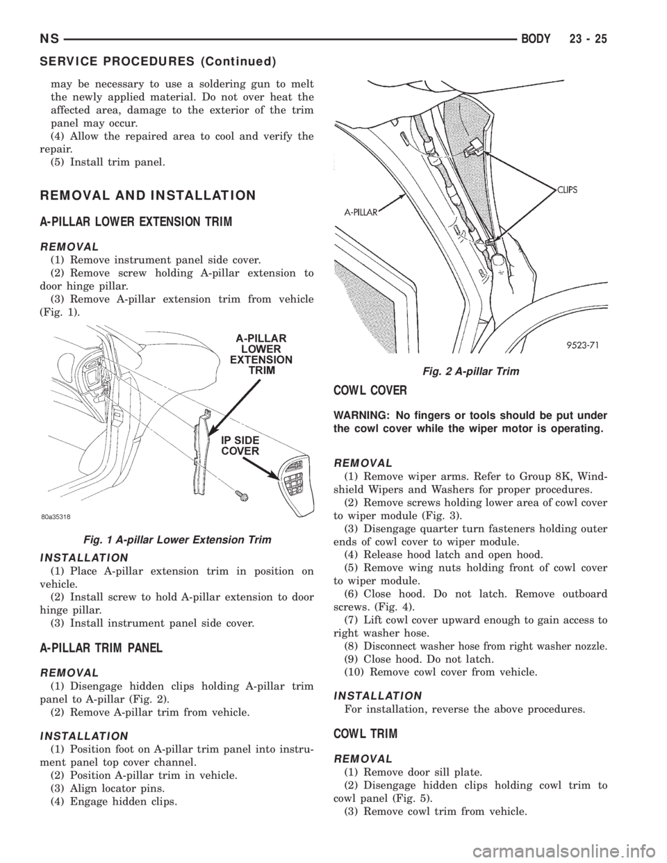
(3) Remove A-pillar extension trim from vehicle
(Fig. 1).
INSTALLATION
(1) Place A-pillar extension trim in position on
vehicle.
(2) Install screw to hold A-pillar extension to door
hinge pillar.
(3) Install instrument panel side cover.
A-PILLAR TRIM PANEL
REMOVAL
(1) Disengage hidden clips holding A-pillar trim
panel to A-pillar (Fig. 2).
(2) Remove A-pillar trim from vehicle.
INSTALLATION
(1) Position foot on A-pillar trim panel into instru-
ment panel top cover channel.
(2) Position A-pillar trim in vehicle.
(3) Align locator pins.
(4) Engage hidden clips.
COWL COVER
WARNING: No fingers or tools should be put under
the cowl cover while the wiper motor is operating.
REMOVAL
(1) Remove wiper arms. Refer to Group 8K, Wind-
shield Wipers and Washers for proper procedures.
(2) Remove screws holding lower area of cowl cover
to wiper module (Fig. 3).
(3) Disengage quarter turn fasteners holding outer
ends of cowl cover to wiper module.
(4) Release hood latch and open hood.
(5) Remove wing nuts holding front of cowl cover
to wiper module.
(6) Close hood. Do not latch. Remove outboard
screws. (Fig. 4).
(7) Lift cowl cover upward enough to gain access to
right washer hose.
(8) D
isconnect washer hose from right washer nozzle.
(9) Close hood. Do not latch.
(10) Remove cowl cover from vehicle.
INSTALLATION
For installation, reverse the above procedures.
COWL TRIM
REMOVAL
(1) Remove door sill plate.
(2) Disengage hidden clips holding cowl trim to
cowl panel (Fig. 5).
(3) Remove cowl trim from vehicle.
Fig. 1 A-pillar Lower Extension Trim
Fig. 2 A-pillar Trim
NSBODY 23 - 25
SERVICE PROCEDURES (Continued)
Page 1771 of 1938
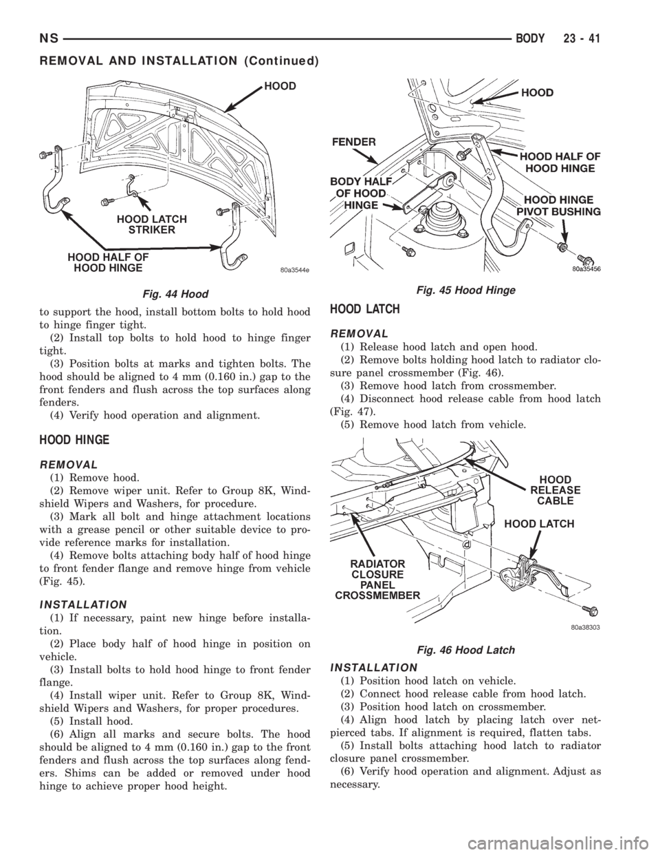
to support the hood, install bottom bolts to hold hood
to hinge finger tight.
(2) Install top bolts to hold hood to hinge finger
tight.
(3) Position bolts at marks and tighten bolts. The
hood should be aligned to 4 mm (0.160 in.) gap to the
front fenders and flush across the top surfaces along
fenders.
(4) Verify hood operation and alignment.
HOOD HINGE
REMOVAL
(1) Remove hood.
(2) Remove wiper unit. Refer to Group 8K, Wind-
shield Wipers and Washers, for procedure.
(3) Mark all bolt and hinge attachment locations
with a grease pencil or other suitable device to pro-
vide reference marks for installation.
(4) Remove bolts attaching body half of hood hinge
to front fender flange and remove hinge from vehicle
(Fig. 45).
INSTALLATION
(1) If necessary, paint new hinge before installa-
tion.
(2) Place body half of hood hinge in position on
vehicle.
(3) Install bolts to hold hood hinge to front fender
flange.
(4) Install wiper unit. Refer to Group 8K, Wind-
shield Wipers and Washers, for proper procedures.
(5) Install hood.
(6) Align all marks and secure bolts. The hood
should be aligned to 4 mm (0.160 in.) gap to the front
fenders and flush across the top surfaces along fend-
ers. Shims can be added or removed under hood
hinge to achieve proper hood height.
HOOD LATCH
REMOVAL
(1) Release hood latch and open hood.
(2) Remove bolts holding hood latch to radiator clo-
sure panel crossmember (Fig. 46).
(3) Remove hood latch from crossmember.
(4) Disconnect hood release cable from hood latch
(Fig. 47).
(5) Remove hood latch from vehicle.
INSTALLATION
(1) Position hood latch on vehicle.
(2) Connect hood release cable from hood latch.
(3) Position hood latch on crossmember.
(4) Align hood latch by placing latch over net-
pierced tabs. If alignment is required, flatten tabs.
(5) Install bolts attaching hood latch to radiator
closure panel crossmember.
(6) Verify hood operation and alignment. Adjust as
necessary.
Fig. 44 HoodFig. 45 Hood Hinge
Fig. 46 Hood Latch
NSBODY 23 - 41
REMOVAL AND INSTALLATION (Continued)
Page 1772 of 1938
(7) Tighten attaching bolts to 11 to 16 N´m (100 to
140 in. lbs.) torque.
HOOD LATCH STRIKER
REMOVAL
(1) Release hood latch and open hood.
(2) Remove bolts holding striker to inside of hood
(Fig. 44).
(3) Remove hood latch striker from vehicle.
INSTALLATION
(1) Position hood latch striker on vehicle.
(2) Install bolts to hold hood latch striker to hood.
(3) Align hood latch striker to engage smoothly
into hood latch.
(4) Verify hood operation and alignment. Adjust as
necessary.
(5) Tighten attaching bolts to 11 to 16 N´m (100 to
140 in. lbs.) torque.
HOOD RELEASE CABLE
REMOVAL
(1) Remove hood latch.
(2) Disengage cable end from hood latch locking
mechanism.
(3) Slide cable case end sideways in keyhole slot of
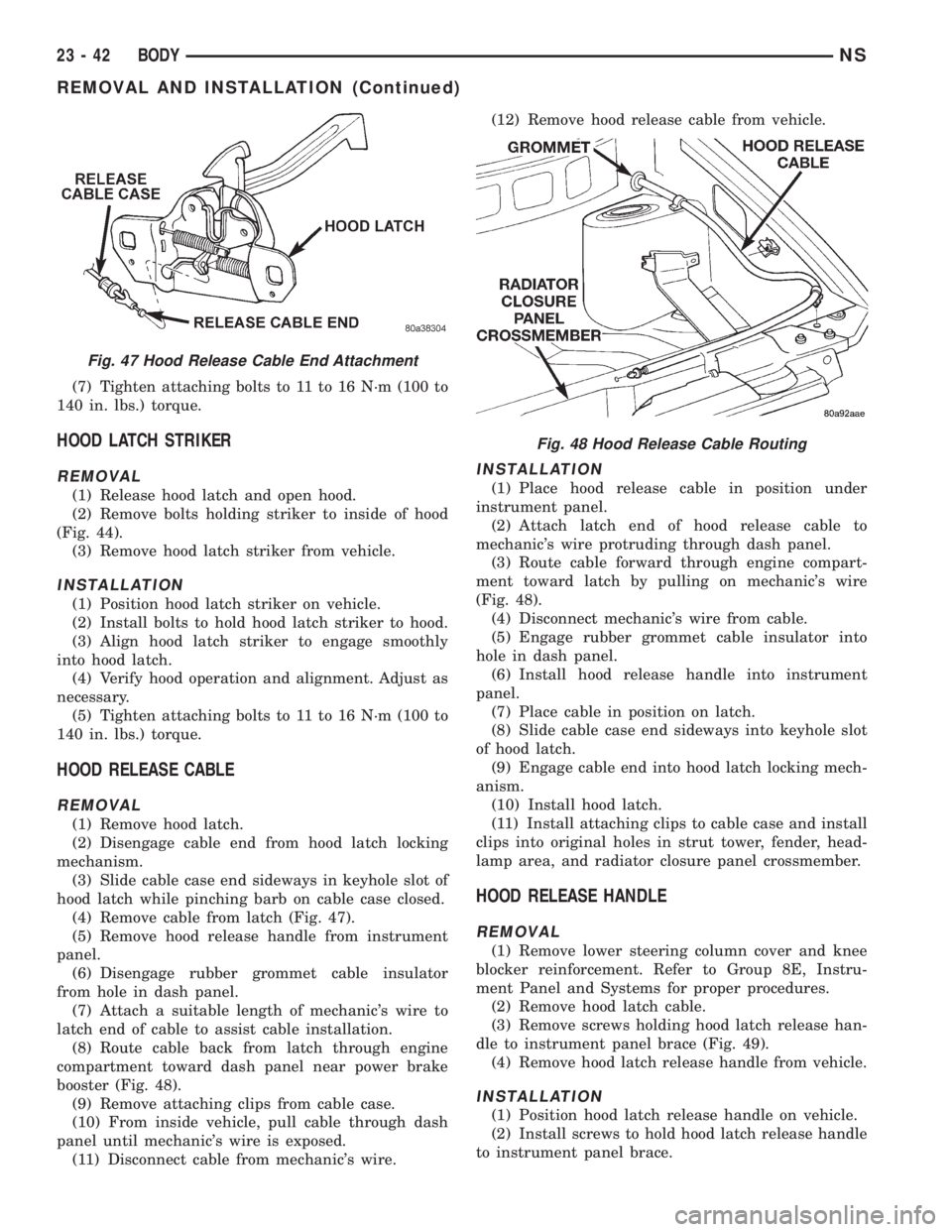
hood latch while pinching barb on cable case closed.
(4) Remove cable from latch (Fig. 47).
(5) Remove hood release handle from instrument
panel.
(6) Disengage rubber grommet cable insulator
from hole in dash panel.
(7) Attach a suitable length of mechanic's wire to
latch end of cable to assist cable installation.
(8) Route cable back from latch through engine
compartment toward dash panel near power brake
booster (Fig. 48).
(9) Remove attaching clips from cable case.
(10) From inside vehicle, pull cable through dash
panel until mechanic's wire is exposed.
(11) Disconnect cable from mechanic's wire.(12) Remove hood release cable from vehicle.
INSTALLATION
(1) Place hood release cable in position under
instrument panel.
(2) Attach latch end of hood release cable to
mechanic's wire protruding through dash panel.
(3) Route cable forward through engine compart-
ment toward latch by pulling on mechanic's wire
(Fig. 48).
(4) Disconnect mechanic's wire from cable.
(5) Engage rubber grommet cable insulator into
hole in dash panel.
(6) Install hood release handle into instrument
panel.
(7) Place cable in position on latch.
(8) Slide cable case end sideways into keyhole slot
of hood latch.
(9) Engage cable end into hood latch locking mech-
anism.
(10) Install hood latch.
(11) Install attaching clips to cable case and install
clips into original holes in strut tower, fender, head-
lamp area, and radiator closure panel crossmember.
HOOD RELEASE HANDLE
REMOVAL
(1) Remove lower steering column cover and knee
blocker reinforcement. Refer to Group 8E, Instru-
ment Panel and Systems for proper procedures.
(2) Remove hood latch cable.
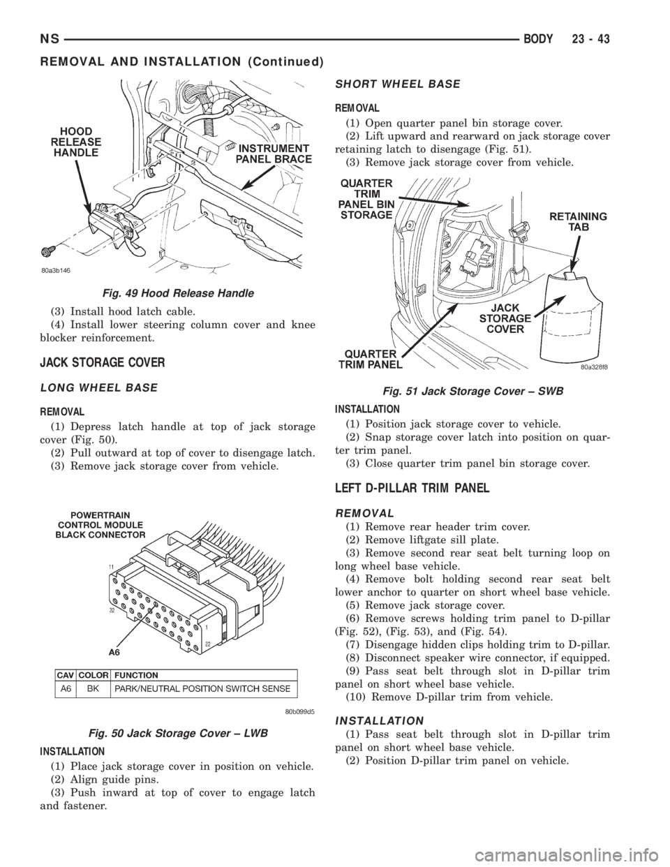
(3) Remove screws holding hood latch release han-
dle to instrument panel brace (Fig. 49).
(4) Remove hood latch release handle from vehicle.
INSTALLATION
(1) Position hood latch release handle on vehicle.
(2) Install screws to hold hood latch release handle
to instrument panel brace.
Fig. 47 Hood Release Cable End Attachment
Fig. 48 Hood Release Cable Routing
23 - 42 BODYNS
REMOVAL AND INSTALLATION (Continued)
Page 1773 of 1938
(3) Install hood latch cable.
(4) Install lower steering column cover and knee
blocker reinforcement.
JACK STORAGE COVER
LONG WHEEL BASE
REMOVAL
(1) Depress latch handle at top of jack storage
cover (Fig. 50).
(2) Pull outward at top of cover to disengage latch.
(3) Remove jack storage cover from vehicle.
INSTALLATION
(1) Place jack storage cover in position on vehicle.
(2) Align guide pins.
(3) Push inward at top of cover to engage latch
and fastener.
SHORT WHEEL BASE
REMOVAL
(1) Open quarter panel bin storage cover.
(2) Lift upward and rearward on jack storage cover
retaining latch to disengage (Fig. 51).
(3) Remove jack storage cover from vehicle.
INSTALLATION
(1) Position jack storage cover to vehicle.
(2) Snap storage cover latch into position on quar-
ter trim panel.
(3) Close quarter trim panel bin storage cover.
LEFT D-PILLAR TRIM PANEL
REMOVAL
(1) Remove rear header trim cover.
(2) Remove liftgate sill plate.
(3) Remove second rear seat belt turning loop on
long wheel base vehicle.
(4) Remove bolt holding second rear seat belt
lower anchor to quarter on short wheel base vehicle.
(5) Remove jack storage cover.
(6) Remove screws holding trim panel to D-pillar
(Fig. 52), (Fig. 53), and (Fig. 54).
(7) Disengage hidden clips holding trim to D-pillar.
(8) Disconnect speaker wire connector, if equipped.
(9) Pass seat belt through slot in D-pillar trim
panel on short wheel base vehicle.
(10) Remove D-pillar trim from vehicle.
INSTALLATION
(1) Pass seat belt through slot in D-pillar trim
panel on short wheel base vehicle.
(2) Position D-pillar trim panel on vehicle.
Fig. 49 Hood Release Handle
Fig. 50 Jack Storage Cover ± LWB
Fig. 51 Jack Storage Cover ± SWB
NSBODY 23 - 43
REMOVAL AND INSTALLATION (Continued)
Page 1783 of 1938
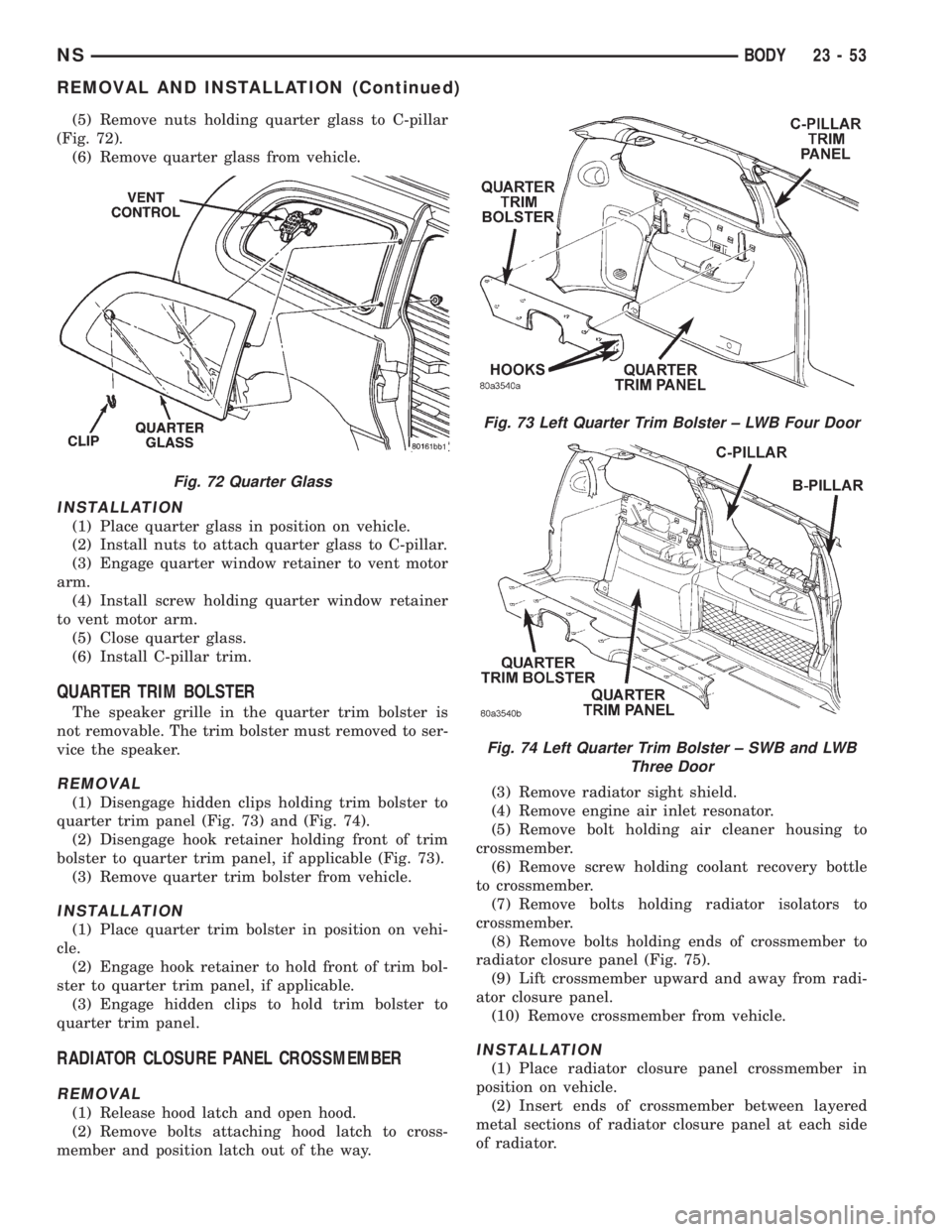
(5) Remove nuts holding quarter glass to C-pillar
(Fig. 72).
(6) Remove quarter glass from vehicle.
INSTALLATION
(1) Place quarter glass in position on vehicle.
(2) Install nuts to attach quarter glass to C-pillar.
(3) Engage quarter window retainer to vent motor
arm.
(4) Install screw holding quarter window retainer
to vent motor arm.
(5) Close quarter glass.
(6) Install C-pillar trim.
QUARTER TRIM BOLSTER
The speaker grille in the quarter trim bolster is
not removable. The trim bolster must removed to ser-
vice the speaker.
REMOVAL
(1) Disengage hidden clips holding trim bolster to
quarter trim panel (Fig. 73) and (Fig. 74).
(2) Disengage hook retainer holding front of trim
bolster to quarter trim panel, if applicable (Fig. 73).
(3) Remove quarter trim bolster from vehicle.
INSTALLATION
(1) Place quarter trim bolster in position on vehi-
cle.
(2) Engage hook retainer to hold front of trim bol-
ster to quarter trim panel, if applicable.
(3) Engage hidden clips to hold trim bolster to
quarter trim panel.
RADIATOR CLOSURE PANEL CROSSMEMBER
REMOVAL
(1) Release hood latch and open hood.
(2) Remove bolts attaching hood latch to cross-
member and position latch out of the way.(3) Remove radiator sight shield.
(4) Remove engine air inlet resonator.
(5) Remove bolt holding air cleaner housing to
crossmember.
(6) Remove screw holding coolant recovery bottle
to crossmember.
(7) Remove bolts holding radiator isolators to
crossmember.
(8) Remove bolts holding ends of crossmember to
radiator closure panel (Fig. 75).
(9) Lift crossmember upward and away from radi-
ator closure panel.
(10) Remove crossmember from vehicle.
INSTALLATION
(1) Place radiator closure panel crossmember in
position on vehicle.
(2) Insert ends of crossmember between layered
metal sections of radiator closure panel at each side
of radiator.
Fig. 72 Quarter Glass
Fig. 73 Left Quarter Trim Bolster ± LWB Four Door
Fig. 74 Left Quarter Trim Bolster ± SWB and LWB
Three Door
NSBODY 23 - 53
REMOVAL AND INSTALLATION (Continued)