1996 CHRYSLER VOYAGER stop start
[x] Cancel search: stop startPage 1225 of 1938
HYDRAULIC TAPPETS
Before disassembling any part of the engine to cor-
rect tappet noise, check the oil pressure. If vehicle
has no oil pressure gauge, install a reliable gauge at
the pressure sending unit. The pressure should be
between 3.5 bars to 5.0 bars at 4000 RPM.
Check the oil level after the engine reaches normal
operating temperature. Allow 5 minutes to stabilize
oil level, check dipstick. The oil level in the pan
should never be above the FULL mark or below the
ADD OIL mark on dipstick. Either of these 2 condi-
tions could be responsible for noisy tappets.
OIL LEVEL HIGH
If oil level is above the FULL mark, it is possible
for the connecting rods to dip into the oil. With the
engine running, this condition could create foam in
the oil pan. Foam in oil pan would be fed to the
hydraulic tappets by the oil pump causing them to
lose length and allow valves to seat noisily.
OIL LEVEL LOW
Low oil level may allow oil pump to take in air.
When air is fed to the tappets, they lose length which
allows valves to seat noisily. Any leaks on intake side
of oil pump through which air can be drawn will cre-
ate the same tappet action. Check the lubrication
system from the intake strainer to the pump cover,
including the relief valve retainer cap. When tappet
noise is due to aeration, it may be intermittent or
constant, and usually more than 1 tappet will be
noisy. When oil level and leaks have been corrected,
operate the engine at fast idle. Run engine for a suf-
ficient time to allow all of the air inside the tappets
to be bled out.
TAPPET NOISE DIAGNOSIS
(1) To determine source of tappet noise, operate
engine at idle with cylinder head covers removed.
(2) Feel each valve spring or rocker arm to detect
noisy tappet. The noisy tappet will cause the affected
spring and/or rocker arm to vibrate or feel rough in
operation.
NOTE: Worn valve guides or cocked springs are
sometimes mistaken for noisy tappets. If such is
the case, noise may be dampened by applying side
thrust on the valve spring. If noise is not apprecia-
bly reduced, it can be assumed the noise is in the
tappet. Inspect the rocker arm push rod sockets
and push rod ends for wear.
(3) Valve tappet noise ranges from light noise to a
heavy click. A light noise is usually caused by exces-
sive leak down around the unit plunger or by the
plunger partially sticking in the tappet body cylinder.
The tappet should be replaced. A heavy click iscaused by a tappet check valve not seating or by for-
eign particles becoming wedged between the plunger
and the tappet body. This will cause the plunger to
stick in the down position. This heavy click will be
accompanied by excessive clearance between the
valve stem and rocker arm as valve closes. In either
case, tappet assembly should be removed for inspec-
tion and cleaning.
(4) The valve train generates a noise very much
like a light tappet noise during normal operation.
Care must be taken to ensure that tappets are mak-
ing the noise. In general, if more than one tappet
seems to be noisy, its probably not the tappets.
SERVICE PROCEDURES
CHECKING OIL LEVEL
To assure proper engine lubrication, the engine oil
must be maintained at the correct level. Check the
oil level at regular intervals, such as every fuel stop.
The best time to check the oil level is about 5 min-
utes after a fully warmed-up engine is shut off, or
before starting the vehicle after it has sat overnight.
Checking the oil while the vehicle is on level
ground, will improve the accuracy of the oil level
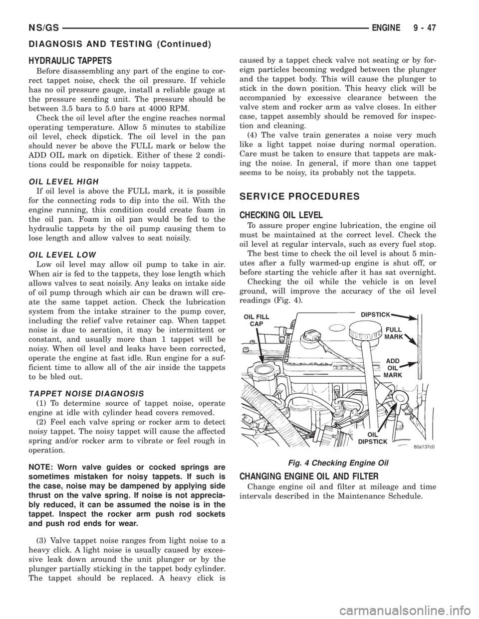
readings (Fig. 4).
CHANGING ENGINE OIL AND FILTER
Change engine oil and filter at mileage and time
intervals described in the Maintenance Schedule.
Fig. 4 Checking Engine Oil
NS/GSENGINE 9 - 47
DIAGNOSIS AND TESTING (Continued)
Page 1226 of 1938
ENGINE OIL CHANGE
WARNING: NEW OR USED ENGINE OIL CAN BE
IRRITATING TO THE SKIN. AVOID PROLONGED OR
REPEATED SKIN CONTACT WITH ENGINE OIL.
CONTAMINANTS IN USED ENGINE OIL, CAUSED BY
INTERNAL COMBUSTION, CAN BE HAZARDOUS TO
YOUR HEALTH. THOROUGHLY WASH EXPOSED
SKIN WITH SOAP AND WATER. DO NOT WASH
SKIN WITH GASOLINE, DIESEL FUEL, THINNER, OR
SOLVENTS, HEALTH PROBLEMS CAN RESULT. DO
NOT POLLUTE, DISPOSE OF USED ENGINE OIL
PROPERLY. CONTACT YOUR DEALER OR GOVERN-
MENT AGENCY FOR LOCATION OF COLLECTION
CENTER IN YOUR AREA.
Run engine until achieving normal operating tem-
perature.
(1) Position the vehicle on a level surface and turn
engine off.
(2) Remove oil fill cap.
(3) Hoist vehicle. Refer to Hoisting and Jacking
Recommendations.
(4) Place a suitable drain pan under crankcase
drain.
(5) Remove drain plug from crankcase and allow
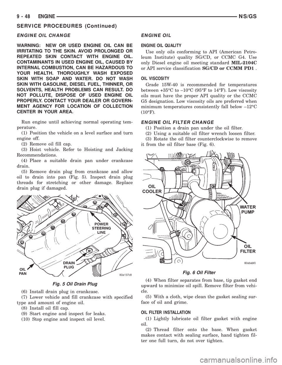
oil to drain into pan (Fig. 5). Inspect drain plug
threads for stretching or other damage. Replace
drain plug if damaged.
(6) Install drain plug in crankcase.
(7) Lower vehicle and fill crankcase with specified
type and amount of engine oil.
(8) Install oil fill cap.
(9) Start engine and inspect for leaks.
(10) Stop engine and inspect oil level.
ENGINE OIL
ENGINE OIL QUALITY
Use only oils conforming to API (American Petro-
leum Institute) quality SG/CD, or CCMC G4. Use
only Diesel engine oil meeting standardMIL-2104C
or API service classificationSG/CD or CCMM PD1.
OIL VISCOSITY
Grade 15W-40 is recommended for temperatures
between +35ÉC to ±10ÉC (95ÉF to 14ÉF). Low viscosity
oils must have the proper API quality or the CCMC
G5 designation. Low viscosity oils are preferred when
minimum temperatures consistently fall below ±12ÉC
(10ÉF).
ENGINE OIL FILTER CHANGE
(1) Position a drain pan under the oil filter.
(2) Using a suitable oil filter wrench loosen filter.
(3) Rotate the oil filter counterclockwise to remove
it from the oil filter base (Fig. 6).
(4) When filter separates from base, tip gasket end
upward to minimize oil spill. Remove filter from vehi-
cle.
(5) With a cloth, wipe clean the gasket sealing sur-
face of oil and grime.
OIL FILTER INSTALLATION
(1) Lightly lubricate oil filter gasket with engine
oil.
(2) Thread filter onto the base. When gasket
makes contact with sealing surface, hand tighten fil-
ter one full turn, do not over tighten.
Fig. 5 Oil Drain Plug
Fig. 6 Oil Filter
9 - 48 ENGINENS/GS
SERVICE PROCEDURES (Continued)
Page 1312 of 1938
INSTALLATION
(1) Position fuel tank on transmission jack. Con-
nect pressure relief/rollover valve hose. Connect fuel
filler tube vent hose and replace clamp.
(2) Raise tank into position and carefully work
filler tube into tank. A light coating of clean engine
oil on the tube end may be used to aid assembly.
(3) Feed filler vent line thru frame rail. Careful
not to cross lines.
(4) Tighten strap bolts to 54 N´m (40 ft. lbs.)
torque. Remove transmission jack.
(5) Tighten filler hose clamp to 3.3 N´m (30 in.
lbs.).
CAUTION: Ensure straps are not twisted or bent
before or after tightening strap nuts.
(6) Connect fuel pump/module electrical connector.
Place retainer in locked position.
(7) Lubricate the fuel supply line with clean 30
weight engine oil, install the quick connect fuel fit-
ting. Refer to Tube/Fitting Assembly in the Fuel
Delivery section of this Group.
(8) Attach filler line to filler tube. Pull on connec-
tor to make sure of connection.
(9) Fill fuel tank, replace cap, and connect battery
negative cable.
CAUTION: When using the ASD Fuel System Test,
the ASD relay and fuel pump relay remain energized
for 7 minutes or until the test is stopped, or until
the ignition switch is turned to the Off position.
(10) Use the DRB scan tool ASD Fuel System Test
to pressurize the fuel system. Check for leaks.
FUEL INJECTOR RAILÐ2.4L
REMOVAL
(1) Perform fuel system pressure release procedure
before servicing or starting repairs.Refer to
Fuel System Pressure Release Procedure in this sec-
tion.
(2) Disconnect negative cable from battery.
(3) Remove air cleaner inlet hose from throttle
body.
(4) Remove throttle cable and speed control cable
(if equipped) from throttle lever.
(5) Remove throttle cables from bracket by com-
pressing retaining tabs.
(6) Remove connector from throttle position sensor.
(7) Remove connector from idle air control motor.
(8) Remove vacuum lines from intake plenum fit-
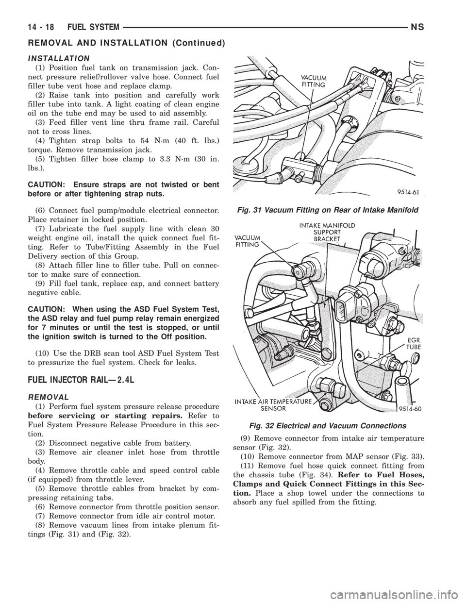
tings (Fig. 31) and (Fig. 32).(9) Remove connector from intake air temperature
sensor (Fig. 32).
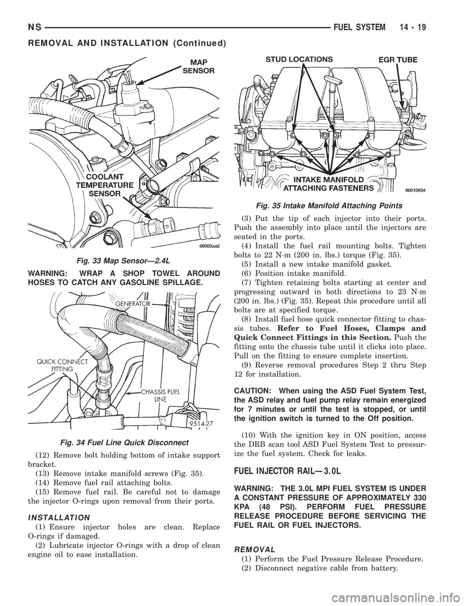
(10) Remove connector from MAP sensor (Fig. 33).
(11) Remove fuel hose quick connect fitting from
the chassis tube (Fig. 34).Refer to Fuel Hoses,
Clamps and Quick Connect Fittings in this Sec-
tion.Place a shop towel under the connections to
absorb any fuel spilled from the fitting.
Fig. 31 Vacuum Fitting on Rear of Intake Manifold
Fig. 32 Electrical and Vacuum Connections
14 - 18 FUEL SYSTEMNS
REMOVAL AND INSTALLATION (Continued)
Page 1313 of 1938
WARNING: WRAP A SHOP TOWEL AROUND
HOSES TO CATCH ANY GASOLINE SPILLAGE.
(12) Remove bolt holding bottom of intake support
bracket.
(13) Remove intake manifold screws (Fig. 35).
(14) Remove fuel rail attaching bolts.
(15) Remove fuel rail. Be careful not to damage
the injector O-rings upon removal from their ports.
INSTALLATION
(1) Ensure injector holes are clean. Replace
O-rings if damaged.
(2) Lubricate injector O-rings with a drop of clean
engine oil to ease installation.(3) Put the tip of each injector into their ports.
Push the assembly into place until the injectors are
seated in the ports.
(4) Install the fuel rail mounting bolts. Tighten
bolts to 22 N´m (200 in. lbs.) torque (Fig. 35).
(5) Install a new intake manifold gasket.
(6) Position intake manifold.
(7) Tighten retaining bolts starting at center and
progressing outward in both directions to 23 N´m
(200 in. lbs.) (Fig. 35). Repeat this procedure until all
bolts are at specified torque.
(8) Install fuel hose quick connector fitting to chas-
sis tubes.Refer to Fuel Hoses, Clamps and
Quick Connect Fittings in this Section.Push the
fitting onto the chassis tube until it clicks into place.
Pull on the fitting to ensure complete insertion.
(9) Reverse removal procedures Step 2 thru Step
12 for installation.
CAUTION: When using the ASD Fuel System Test,
the ASD relay and fuel pump relay remain energized
for 7 minutes or until the test is stopped, or until
the ignition switch is turned to the Off position.
(10) With the ignition key in ON position, access
the DRB scan tool ASD Fuel System Test to pressur-
ize the fuel system. Check for leaks.
FUEL INJECTOR RAILÐ3.0L
WARNING: THE 3.0L MPI FUEL SYSTEM IS UNDER
A CONSTANT PRESSURE OF APPROXIMATELY 330
KPA (48 PSI). PERFORM FUEL PRESSURE
RELEASE PROCEDURE BEFORE SERVICING THE
FUEL RAIL OR FUEL INJECTORS.
REMOVAL
(1) Perform the Fuel Pressure Release Procedure.
(2) Disconnect negative cable from battery.
Fig. 33 Map SensorÐ2.4L
Fig. 34 Fuel Line Quick Disconnect
Fig. 35 Intake Manifold Attaching Points
NSFUEL SYSTEM 14 - 19
REMOVAL AND INSTALLATION (Continued)
Page 1373 of 1938
For periodic draining of water from the bowl, refer
to Fuel Filter/Water Separator Removal/Installation
in this group.
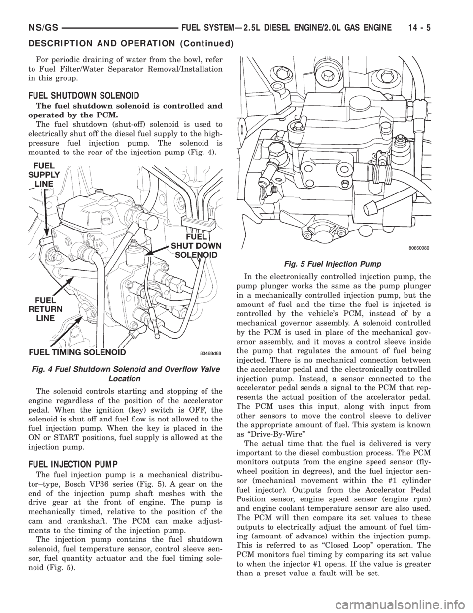
FUEL SHUTDOWN SOLENOID
The fuel shutdown solenoid is controlled and
operated by the PCM.
The fuel shutdown (shut-off) solenoid is used to
electrically shut off the diesel fuel supply to the high-
pressure fuel injection pump. The solenoid is
mounted to the rear of the injection pump (Fig. 4).
The solenoid controls starting and stopping of the
engine regardless of the position of the accelerator
pedal. When the ignition (key) switch is OFF, the
solenoid is shut off and fuel flow is not allowed to the
fuel injection pump. When the key is placed in the
ON or START positions, fuel supply is allowed at the
injection pump.
FUEL INJECTION PUMP
The fuel injection pump is a mechanical distribu-
tor±type, Bosch VP36 series (Fig. 5). A gear on the
end of the injection pump shaft meshes with the
drive gear at the front of engine. The pump is
mechanically timed, relative to the position of the
cam and crankshaft. The PCM can make adjust-
ments to the timing of the injection pump.
The injection pump contains the fuel shutdown
solenoid, fuel temperature sensor, control sleeve sen-
sor, fuel quantity actuator and the fuel timing sole-
noid (Fig. 5).In the electronically controlled injection pump, the
pump plunger works the same as the pump plunger
in a mechanically controlled injection pump, but the
amount of fuel and the time the fuel is injected is
controlled by the vehicle's PCM, instead of by a
mechanical governor assembly. A solenoid controlled
by the PCM is used in place of the mechanical gov-
ernor assembly, and it moves a control sleeve inside
the pump that regulates the amount of fuel being
injected. There is no mechanical connection between
the accelerator pedal and the electronically controlled
injection pump. Instead, a sensor connected to the
accelerator pedal sends a signal to the PCM that rep-
resents the actual position of the accelerator pedal.
The PCM uses this input, along with input from
other sensors to move the control sleeve to deliver
the appropriate amount of fuel. This system is known
as ªDrive-By-Wireº
The actual time that the fuel is delivered is very
important to the diesel combustion process. The PCM
monitors outputs from the engine speed sensor (fly-
wheel position in degrees), and the fuel injector sen-
sor (mechanical movement within the #1 cylinder
fuel injector). Outputs from the Accelerator Pedal
Position sensor, engine speed sensor (engine rpm)
and engine coolant temperature sensor are also used.
The PCM will then compare its set values to these
outputs to electrically adjust the amount of fuel tim-
ing (amount of advance) within the injection pump.
This is referred to as ªClosed Loopº operation. The
PCM monitors fuel timing by comparing its set value
to when the injector #1 opens. If the value is greater
than a preset value a fault will be set.
Fig. 4 Fuel Shutdown Solenoid and Overflow Valve
Location
Fig. 5 Fuel Injection Pump
NS/GSFUEL SYSTEMÐ2.5L DIESEL ENGINE/2.0L GAS ENGINE 14 - 5
DESCRIPTION AND OPERATION (Continued)
Page 1381 of 1938
A defective fuel injection pump, defective fuel tim-
ing solenoid or misadjusted mechanical pump timing
can cause starting problems or prevent the engine
from revving up. It can also cause:
²Engine surge at idle
²Rough idle (warm engine)
²Low power
²Excessive fuel consumption
²Poor performance
²Low power
²Black smoke from the exhaust
²Blue or white fog like exhaust
²Incorrect idle or maximum speed
The electronically controlled fuel pump has no
mechanical governor like older mechanically con-
trolled fuel pumps. Do not remove the top cover of
the fuel pump, or the screws fastening the wiring
pigtail to the side of the pump.The warranty of
the injection pump and the engine may be void
if those seals have been removed or tampered
with.
FUEL SUPPLY RESTRICTIONS
LOW±PRESSURE LINES
Restricted or Plugged supply lines or fuel filter can
cause a timing fault that will cause the PCM to oper-
ate the engine in a ªLimp Homeº mode. See the
introduction of the Fuel Injection System in this
group for more information on the Limp Home mode.
Fuel supply line restrictions can cause starting prob-
lems and prevent the engine from revving up. The
starting problems include; low power and blue or
white fog like exhaust. Test all fuel supply lines for
restrictions or blockage. Flush or replace as neces-
sary. Bleed the fuel system of air once a fuel supply
line has been replaced. Refer to the Air Bleed Proce-
dure section of this group for procedures.
HIGH±PRESSURE LINES
Restricted (kinked or bent) high±pressure lines can
cause starting problems, poor engine performance
and black smoke from exhaust.
Examine all high±pressure lines for any damage.
Each radius on each high±pressure line must be
smooth and free of any bends or kinks.
Replace damaged, restricted or leaking high±pres-
sure fuel lines with the correct replacement line.
CAUTION: The high±pressure fuel lines must be
clamped securely in place in the holders. The lines
cannot contact each other or other components. Do
not attempt to weld high±pressure fuel lines or to
repair lines that are damaged. Only use the recom-
mended lines when replacement of high±pressure
fuel line is necessary.
FUEL SHUTDOWN SOLENOID TEST
Since diesel fuel injection does not use spark plugs
to start combustion, the only way to stop the engine
is to cut off the fuel supply. This is done with the
Fuel Shutdown Solenoid. If the engine cranks, but
refuses to start, it may be caused by a defective fuel
shutdown solenoid.
The fuel shutdown solenoid is not controlled
or operated by the PCM.Voltage to operate the
solenoid is supplied from the ignition (key) switch.
NOTE: Although the fuel shutdown solenoid is not
operated by the PCM, if the Fuel Shutdown Solenoid
has been disconnected, and the key turned on, the
PCM will sense that the solenoid is not in the circuit,
and will switch to a ªLimp Homeº mode. After recon-
necting the solenoid, the PCM will have to be reset
by clearing the codes with the DRBIII scan tool, or
disconnecting the vehicle's battery for several min-
utes. The DRBIII scan tool is the preferred method
for resetting the PCM. Refer to the 1998 GS 2.5L Die-
sel Powertrain Diagnostic Manual for procedure.
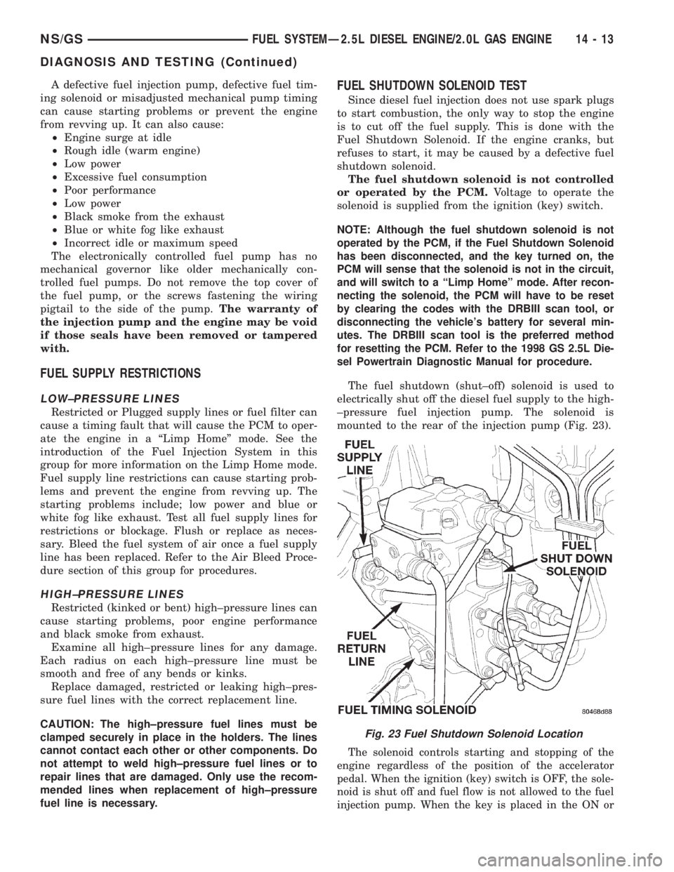
The fuel shutdown (shut±off) solenoid is used to
electrically shut off the diesel fuel supply to the high-
±pressure fuel injection pump. The solenoid is
mounted to the rear of the injection pump (Fig. 23).
The solenoid controls starting and stopping of the
engine regardless of the position of the accelerator
pedal. When the ignition (key) switch is OFF, the sole-
noid is shut off and fuel flow is not allowed to the fuel
injection pump. When the key is placed in the ON or
Fig. 23 Fuel Shutdown Solenoid Location
NS/GSFUEL SYSTEMÐ2.5L DIESEL ENGINE/2.0L GAS ENGINE 14 - 13
DIAGNOSIS AND TESTING (Continued)
Page 1414 of 1938
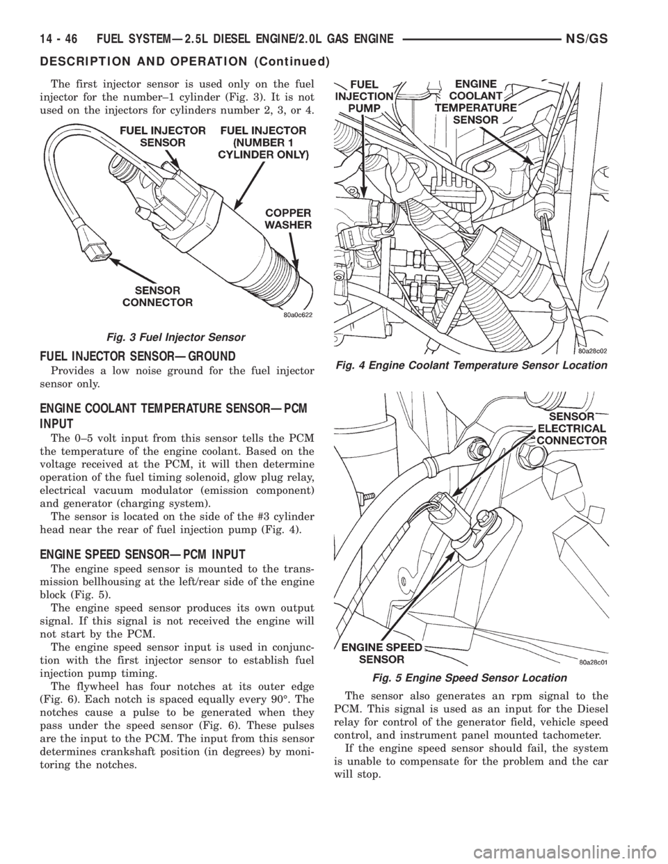
The first injector sensor is used only on the fuel
injector for the number±1 cylinder (Fig. 3). It is not
used on the injectors for cylinders number 2, 3, or 4.
FUEL INJECTOR SENSORÐGROUND
Provides a low noise ground for the fuel injector
sensor only.
ENGINE COOLANT TEMPERATURE SENSORÐPCM
INPUT
The 0±5 volt input from this sensor tells the PCM
the temperature of the engine coolant. Based on the
voltage received at the PCM, it will then determine
operation of the fuel timing solenoid, glow plug relay,
electrical vacuum modulator (emission component)
and generator (charging system).
The sensor is located on the side of the #3 cylinder
head near the rear of fuel injection pump (Fig. 4).
ENGINE SPEED SENSORÐPCM INPUT
The engine speed sensor is mounted to the trans-
mission bellhousing at the left/rear side of the engine
block (Fig. 5).
The engine speed sensor produces its own output
signal. If this signal is not received the engine will
not start by the PCM.
The engine speed sensor input is used in conjunc-
tion with the first injector sensor to establish fuel
injection pump timing.
The flywheel has four notches at its outer edge
(Fig. 6). Each notch is spaced equally every 90É. The
notches cause a pulse to be generated when they
pass under the speed sensor (Fig. 6). These pulses
are the input to the PCM. The input from this sensor
determines crankshaft position (in degrees) by moni-
toring the notches.The sensor also generates an rpm signal to the
PCM. This signal is used as an input for the Diesel
relay for control of the generator field, vehicle speed
control, and instrument panel mounted tachometer.
If the engine speed sensor should fail, the system
is unable to compensate for the problem and the car
will stop.
Fig. 3 Fuel Injector Sensor
Fig. 4 Engine Coolant Temperature Sensor Location
Fig. 5 Engine Speed Sensor Location
14 - 46 FUEL SYSTEMÐ2.5L DIESEL ENGINE/2.0L GAS ENGINENS/GS
DESCRIPTION AND OPERATION (Continued)
Page 1416 of 1938
The speed sensor generates 8 pulses per sensor
revolution. These signals, in conjunction with a
closed throttle signal from the throttle position sen-
sor, indicate a closed throttle deceleration to the
PCM. When the vehicle is stopped at idle, a closed
throttle signal is received by the PCM (but a speed
sensor signal is not received).
In addition to determining distance and vehicle
speed, the output from the sensor is used to control
speed control operation.
SPEED CONTROLÐPCM INPUTS
The speed control system provides five separate
inputs to the PCM; On/Off, Set, Resume/Accel, Cancel,
and Decel.. The On/Off input informs the PCM that
the speed control system has been activated. The Set
input informs the PCM that a fixed vehicle speed has
been selected. The Resume input indicates to the PCM
that the previous fixed speed is requested.
Speed control operation will start at 50 km/h±142
km/h (35±85 mph). The upper range of operation is
not restricted by vehicle speed. Inputs that affect
speed control operation are vehicle speed sensor and
throttle position sensor.
Refer to Group 8H for further speed control infor-
mation.
DIESEL PCM RELAYÐPCM INPUT
A 12 volt signal at this input indicates to the PCM
that the Diesel relay has been activated. The Diesel
relay is located in the PDC. The PDC is located next
to the battery in the engine compartment. For the
location of the relay within the PDC, refer to label on
PDC cover.
This input is used only to sense that the Diesel
relay is energized. If the PCM does not see 12 volts +
at this input when the Diesel relay should be acti-
vated, it will set a Diagnostic Trouble Code (DTC).
FIVE VOLT POWERÐPCM OUTPUT
This circuit supplies approximately 5 volts to
power the Accelerator Pedal Postion Sensor, Mass Air
Flow Sensor, and A/C Pressure Sensor.
ENGINE COOLANT GAUGEÐPCM OUTPUT
Refer to the Instrument Panel and Gauges group
for additional information.
ENGINE OIL PRESSURE GAUGEÐPCM OUTPUT
Refer to the Instrument Panel and Gauges group
for additional information.
GLOW PLUG LAMPÐPCM OUTPUT
The Glow Plug lamp (malfunction indicator lamp)
illuminates on the message center each time the igni-
tion (key) switch is turned on. It will stay on for
about two seconds as a bulb test.If the PCM receives an incorrect signal, or no sig-
nal from certain sensors or components, the lamp
BLINKS. This is a warning that the PCM has
recorded a system or sensor malfunction. It signals
an immediate need for service. There are only 5
HARD faults that can turn on this lamp to make it
blink.
SPEED CONTROLÐPCM OUTPUTS
These two circuits control the fuel quantity actua-
tor to regulate vehicle speed. Refer to Group 8H for
Speed Control information.
AIR CONDITIONING RELAYÐPCM OUTPUT
This circuit controls a ground signal for operation
of the A/C clutch relay. Also refer to Air Conditioning
(A/C) ControlsÐPCM Input for additional informa-
tion.
The A/C relay is located in the Power Distribution
Center (PDC). The PDC is located next to the battery
in the engine compartment. For the location of the
relay within the PDC, refer to label on PDC cover.
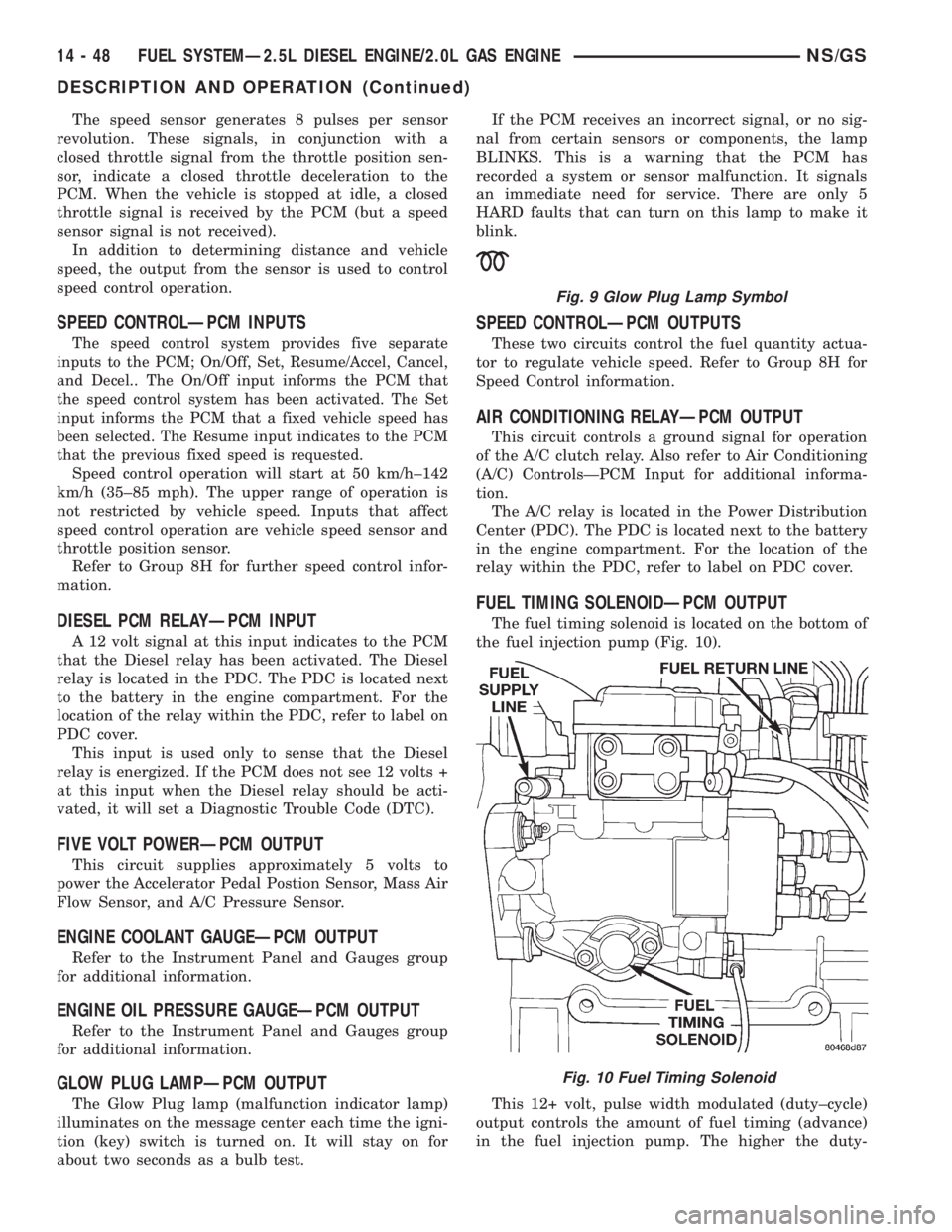
FUEL TIMING SOLENOIDÐPCM OUTPUT
The fuel timing solenoid is located on the bottom of
the fuel injection pump (Fig. 10).
This 12+ volt, pulse width modulated (duty±cycle)
output controls the amount of fuel timing (advance)
in the fuel injection pump. The higher the duty-
Fig. 9 Glow Plug Lamp Symbol
Fig. 10 Fuel Timing Solenoid
14 - 48 FUEL SYSTEMÐ2.5L DIESEL ENGINE/2.0L GAS ENGINENS/GS
DESCRIPTION AND OPERATION (Continued)