Page 1459 of 1938
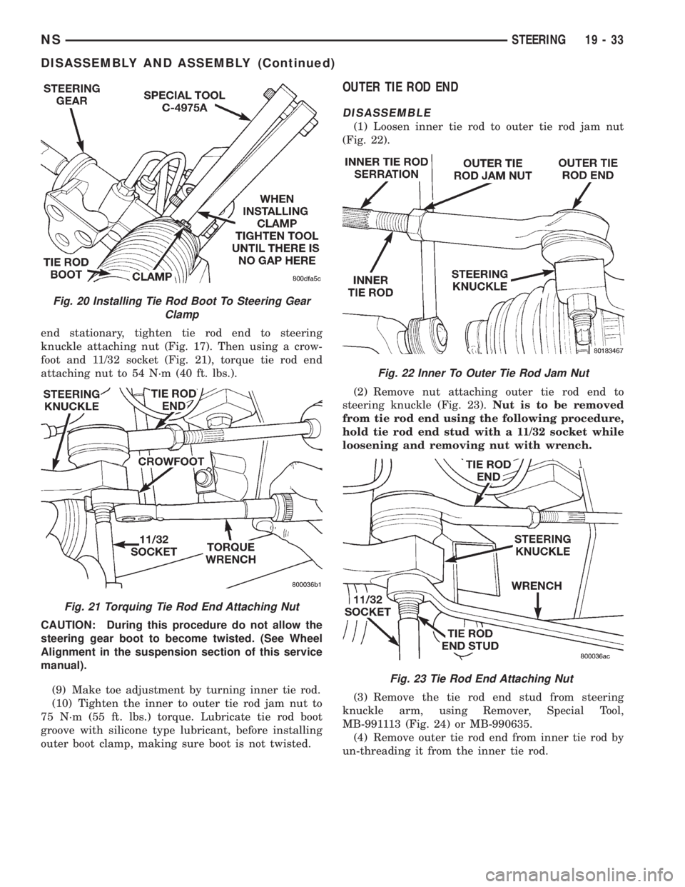
end stationary, tighten tie rod end to steering
knuckle attaching nut (Fig. 17). Then using a crow-
foot and 11/32 socket (Fig. 21), torque tie rod end
attaching nut to 54 N´m (40 ft. lbs.).
CAUTION: During this procedure do not allow the
steering gear boot to become twisted. (See Wheel
Alignment in the suspension section of this service
manual).
(9) Make toe adjustment by turning inner tie rod.
(10) Tighten the inner to outer tie rod jam nut to
75 N´m (55 ft. lbs.) torque. Lubricate tie rod boot
groove with silicone type lubricant, before installing
outer boot clamp, making sure boot is not twisted.
OUTER TIE ROD END
DISASSEMBLE
(1) Loosen inner tie rod to outer tie rod jam nut
(Fig. 22).
(2) Remove nut attaching outer tie rod end to
steering knuckle (Fig. 23).Nut is to be removed
from tie rod end using the following procedure,
hold tie rod end stud with a 11/32 socket while
loosening and removing nut with wrench.
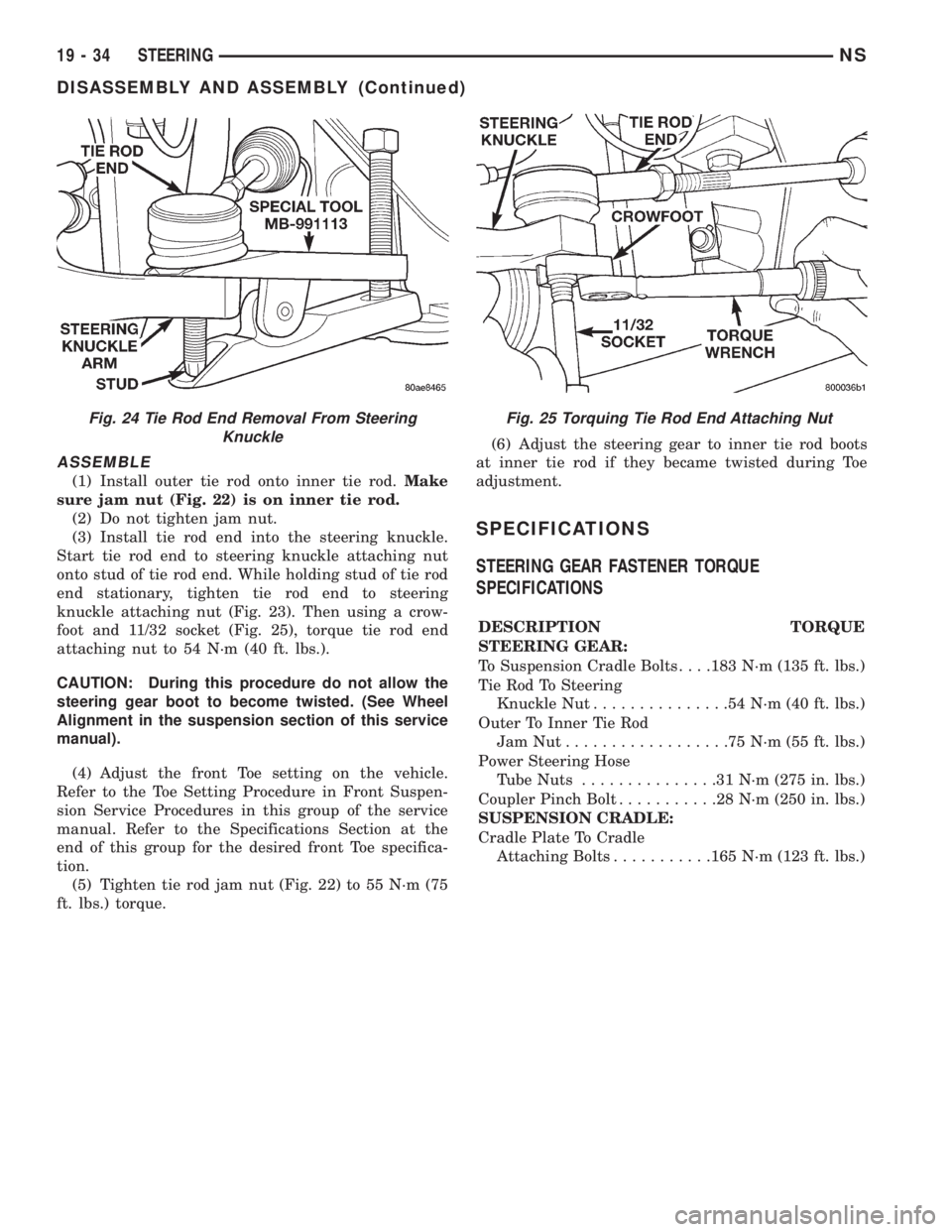
(3) Remove the tie rod end stud from steering
knuckle arm, using Remover, Special Tool,
MB-991113 (Fig. 24) or MB-990635.
(4) Remove outer tie rod end from inner tie rod by
un-threading it from the inner tie rod.
Fig. 20 Installing Tie Rod Boot To Steering Gear
Clamp
Fig. 21 Torquing Tie Rod End Attaching Nut
Fig. 22 Inner To Outer Tie Rod Jam Nut
Fig. 23 Tie Rod End Attaching Nut
NSSTEERING 19 - 33
DISASSEMBLY AND ASSEMBLY (Continued)
Page 1460 of 1938
ASSEMBLE
(1) Install outer tie rod onto inner tie rod.Make
sure jam nut (Fig. 22) is on inner tie rod.
(2) Do not tighten jam nut.
(3) Install tie rod end into the steering knuckle.
Start tie rod end to steering knuckle attaching nut
onto stud of tie rod end. While holding stud of tie rod
end stationary, tighten tie rod end to steering
knuckle attaching nut (Fig. 23). Then using a crow-
foot and 11/32 socket (Fig. 25), torque tie rod end
attaching nut to 54 N´m (40 ft. lbs.).
CAUTION: During this procedure do not allow the
steering gear boot to become twisted. (See Wheel
Alignment in the suspension section of this service
manual).
(4) Adjust the front Toe setting on the vehicle.
Refer to the Toe Setting Procedure in Front Suspen-
sion Service Procedures in this group of the service
manual. Refer to the Specifications Section at the
end of this group for the desired front Toe specifica-
tion.
(5) Tighten tie rod jam nut (Fig. 22) to 55 N´m (75
ft. lbs.) torque.(6) Adjust the steering gear to inner tie rod boots
at inner tie rod if they became twisted during Toe
adjustment.
SPECIFICATIONS
STEERING GEAR FASTENER TORQUE
SPECIFICATIONS
DESCRIPTION TORQUE
STEERING GEAR:
To Suspension Cradle Bolts. . . .183 N´m (135 ft. lbs.)
Tie Rod To Steering
Knuckle Nut...............54N´m(40ft.lbs.)
Outer To Inner Tie Rod
JamNut..................75N´m(55ft.lbs.)
Power Steering Hose
Tube Nuts...............31N´m(275 in. lbs.)
Coupler Pinch Bolt...........28N´m(250 in. lbs.)
SUSPENSION CRADLE:
Cradle Plate To Cradle
Attaching Bolts...........165 N´m (123 ft. lbs.)
Fig. 24 Tie Rod End Removal From Steering
KnuckleFig. 25 Torquing Tie Rod End Attaching Nut
19 - 34 STEERINGNS
DISASSEMBLY AND ASSEMBLY (Continued)
Page 1920 of 1938
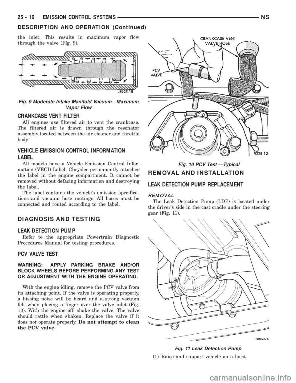
the inlet. This results in maximum vapor flow
through the valve (Fig. 9).
CRANKCASE VENT FILTER
All engines use filtered air to vent the crankcase.
The filtered air is drawn through the resonator
assembly located between the air cleaner and throttle
body.
VEHICLE EMISSION CONTROL INFORMATION
LABEL
All models have a Vehicle Emission Control Infor-
mation (VECI) Label. Chrysler permanently attaches
the label in the engine compartment. It cannot be
removed without defacing information and destroying
the label.
The label contains the vehicle's emission specifica-
tions and vacuum hose routings. All hoses must be
connected and routed according to the label.
DIAGNOSIS AND TESTING
LEAK DETECTION PUMP
Refer to the appropriate Powertrain Diagnostic
Procedures Manual for testing procedures.
PCV VALVE TEST
WARNING: APPLY PARKING BRAKE AND/OR
BLOCK WHEELS BEFORE PERFORMING ANY TEST
OR ADJUSTMENT WITH THE ENGINE OPERATING.
With the engine idling, remove the PCV valve from
its attaching point. If the valve is operating properly,
a hissing noise will be heard and a strong vacuum
felt when placing a finger over the valve inlet (Fig.
10). With the engine off, shake the valve. The valve
should rattle when shaken. Replace the valve if it
does not operate properly.Do not attempt to clean
the PCV valve.
REMOVAL AND INSTALLATION
LEAK DETECTION PUMP REPLACEMENT
REMOVAL
The Leak Detection Pump (LDP) is located under
the driver's side in the cast cradle under the steering
gear (Fig. 11).
(1) Raise and support vehicle on a hoist.
Fig. 9 Moderate Intake Manifold VacuumÐMaximum
Vapor Flow
Fig. 10 PCV Test ÐTypical
Fig. 11 Leak Detection Pump
25 - 16 EMISSION CONTROL SYSTEMSNS
DESCRIPTION AND OPERATION (Continued)
Page:
< prev 1-8 9-16 17-24