1996 CHRYSLER VOYAGER length
[x] Cancel search: lengthPage 1103 of 1938
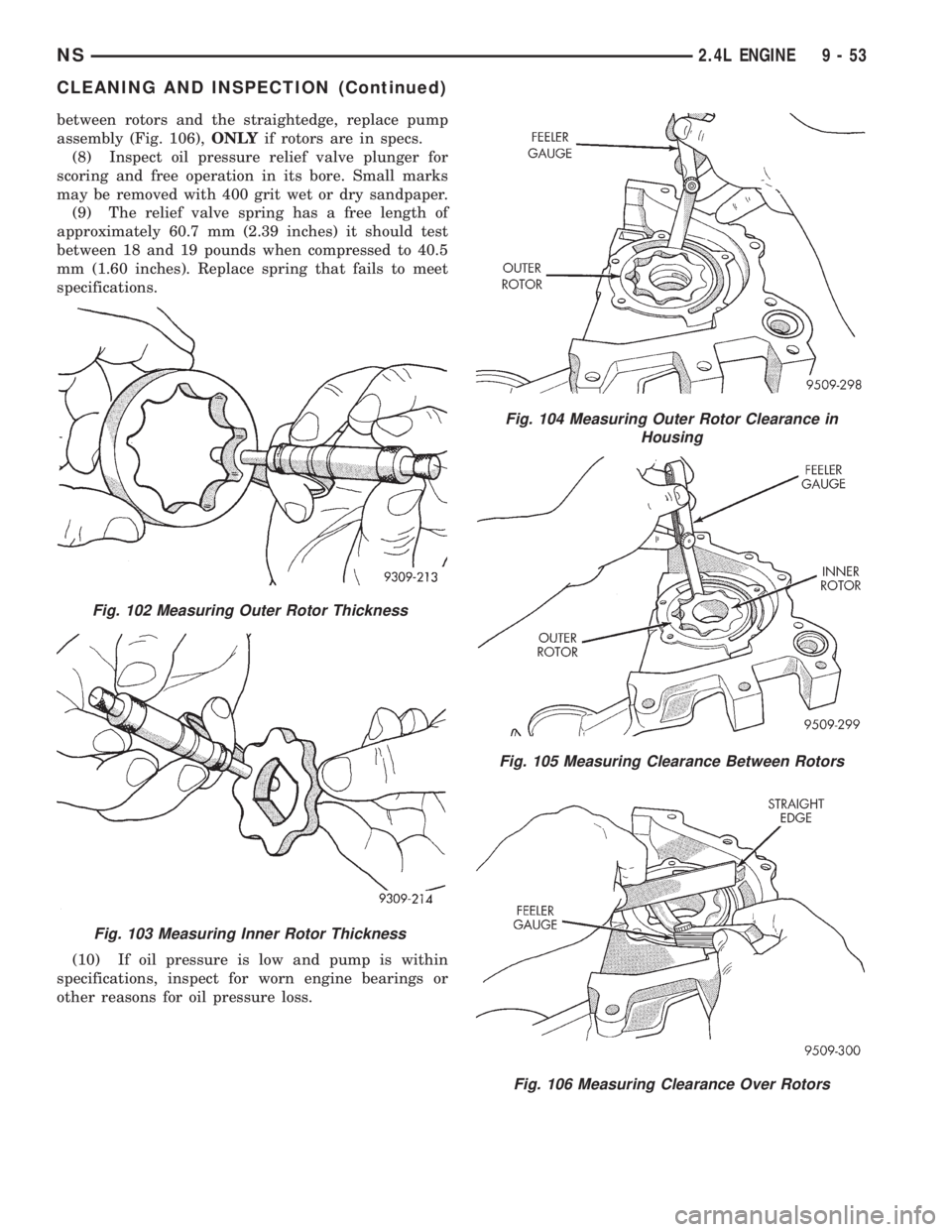
between rotors and the straightedge, replace pump
assembly (Fig. 106),ONLYif rotors are in specs.
(8) Inspect oil pressure relief valve plunger for
scoring and free operation in its bore. Small marks
may be removed with 400 grit wet or dry sandpaper.
(9) The relief valve spring has a free length of
approximately 60.7 mm (2.39 inches) it should test
between 18 and 19 pounds when compressed to 40.5
mm (1.60 inches). Replace spring that fails to meet
specifications.
(10) If oil pressure is low and pump is within
specifications, inspect for worn engine bearings or
other reasons for oil pressure loss.
Fig. 102 Measuring Outer Rotor Thickness
Fig. 103 Measuring Inner Rotor Thickness
Fig. 104 Measuring Outer Rotor Clearance in
Housing
Fig. 105 Measuring Clearance Between Rotors
Fig. 106 Measuring Clearance Over Rotors
NS2.4L ENGINE 9 - 53
CLEANING AND INSPECTION (Continued)
Page 1104 of 1938
CYLINDER BLOCK
(1) Clean cylinder block thoroughly and check all
core hole plugs for evidence of leaking.
(2) If new core plugs are installed, refer to Engine
Core Plugs outlined in this section.
(3) Examine block and cylinder bores for cracks or
fractures.
CYLINDER BORE INSPECTION
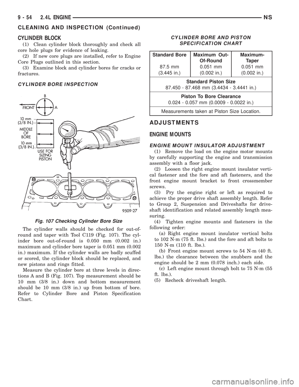
The cylinder walls should be checked for out-of-
round and taper with Tool C119 (Fig. 107). The cyl-
inder bore out-of-round is 0.050 mm (0.002 in.)
maximum and cylinder bore taper is 0.051 mm (0.002
in.) maximum. If the cylinder walls are badly scuffed
or scored, the cylinder block should be replaced, and
new pistons and rings fitted.
Measure the cylinder bore at three levels in direc-
tions A and B (Fig. 107). Top measurement should be
10 mm (3/8 in.) down and bottom measurement
should be 10 mm (3/8 in.) up from bottom of bore.
Refer to Cylinder Bore and Piston Specification
Chart.
ADJUSTMENTS
ENGINE MOUNTS
ENGINE MOUNT INSULATOR ADJUSTMENT
(1) Remove the load on the engine motor mounts
by carefully supporting the engine and transmission
assembly with a floor jack.
(2) Loosen the right engine mount insulator verti-
cal fastener and the fore and aft fasteners, and the
front engine mount bracket to front crossmember
screws.
(3) Pry the engine right or left as required to
achieve the proper drive shaft assembly length. Refer
to Group 2, Suspension and Driveshafts for drive-
shaft identification and related assembly length mea-
suring.
(4) Tighten engine mounts and fasteners in the
following order:
(a) Right engine mount insulator vertical bolts
to 102 N´m (75 ft. lbs.) and the fore and aft bolts to
150 N´m (110 ft. lbs.).
(b) Front engine mount screws to 54 N´m (40 ft.
lbs.) the clearance between the snubbers and the
engine should be 2 mm (0.078 inch.) each side.
(c) Left engine mount through bolt to 75 N´m (55
ft. lbs.).
(5) Recheck driveshaft length.
Fig. 107 Checking Cylinder Bore Size
CYLINDER BORE AND PISTON
SPECIFICATION CHART
Standard Bore Maximum Out-
Of-RoundMaximum-
Taper
87.5 mm 0.051 mm 0.051 mm
(3.445 in.) (0.002 in.) (0.002 in.)
Standard Piston Size
87.450 - 87.468 mm (3.4434 - 3.4441 in.)
Piston To Bore Clearance
0.024 - 0.057 mm (0.0009 - 0.0022 in.)
Measurements taken at Piston Size Location.
9 - 54 2.4L ENGINENS
CLEANING AND INSPECTION (Continued)
Page 1105 of 1938
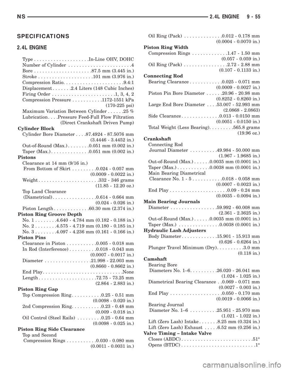
SPECIFICATIONS
2.4L ENGINE
Type....................In-Line OHV, DOHC
Number of Cylinder.......................4
Bore.....................87.5 mm (3.445 in.)
Stroke....................101 mm (3.976 in.)
Compression Ratio......................9.4:1
Displacement.......2.4 Liters (148 Cubic Inches)
Firing Order.......................1,3,4,2
Compression Pressure...........1172-1551 kPa
(170-225 psi)
Maximum Variation Between Cylinder......25%
Lubrication. . . .Pressure Feed-Full Flow Filtration
(Direct Crankshaft Driven Pump)
Cylinder Block
Cylinder Bore Diameter. . . .87.4924 - 87.5076 mm
(3.4446 - 3.4452 in.)
Out-of-Round (Max.)........0.051 mm (0.002 in.)
Taper (Max.)..............0.051 mm (0.002 in.)
Pistons
Clearance at 14 mm (9/16 in.)
From Bottom of Skirt.........0.024 - 0.057 mm
(0.0009 - 0.0022 in.)
Weight......................332 - 346 grams
(11.85 - 12.20 oz.)
Top Land Clearance
(Diametrical)................0.614 - 0.664 mm
(0.024 - 0.026 in.)
Piston Length.............60.30 mm (2.374 in.)
Piston Ring Groove Depth
No.1........4.640 - 4.784 mm (0.182 - 0.188 in.)
No.2........4.575 - 4.719 mm (0.180 - 0.185 in.)
No.3........4.097 - 4.236 mm (0.161 - 0.166 in.)
Piston Pins
Clearance in Piston...........0.005 - 0.018 mm
In Rod (Interference)..........0.018 - 0.043 mm
(0.0007 - 0.0017 in.)
Diameter.................21.998 - 22.003 mm
(0.8660 - 0.8662 in.)
End Play.............................None
Length.....................72.75 - 73.25 mm
(2.864 - 2.883 in.)
Piston Ring Gap
Top Compression Ring...........0.25 - 0.51 mm
(0.0098 - 0.020 in.)
2nd Compression Ring...........0.23 - 0.48 mm
(0.009 - 0.018 in.)
Oil Control (Steel Rails).........0.25 - 0.64 mm
(0.0098 - 0.025 in.)
Piston Ring Side Clearance
Top and Second
Compression Rings...........0.030 - 0.080 mm
(0.0011 - 0.0031 in.)Oil Ring (Pack)..............0.012 - 0.178 mm
(0.0004 - 0.0070 in.)
Piston Ring Width
Compression Rings.............1.47 - 1.50 mm
(0.057 - 0.059 in.)
Oil Ring (Pack)................2.72 - 2.88 mm
(0.107 - 0.1133 in.)
Connecting Rod
Bearing Clearance............0.025 - 0.071 mm
(0.0009 - 0.0027 in.)
Piston Pin Bore Diameter......20.96 - 20.98 mm
(0.8252 - 0.8260 in.)
Large End Bore Diameter. . . .53.007 - 52.993 mm
(2.0868 - 2.0863)
Side Clearance..............0.013 - 0.0150 mm
(0.0051 - 0.0150 in.)
Total Weight (Less Bearing).........565.8 grams
(19.96 oz.)
Crankshaft
Connecting Rod
Journal Diameter..........49.984 - 50.000 mm
(1.967 - 1.9685 in.)
Out-of-Round (Max.)......0.0035 mm (0.0001 in.)
Taper (Max.)............0.0038 mm (0.0001 in.)
Main Bearing Diametrical
Clearance No.1-5...........0.018 - 0.058 mm
(0.0007 - 0.0023 in.)
End Play.....................0.09 - 0.24 mm
(0.0035 - 0.0094 in.)
Main Bearing Journals
Diameter.................59.992 - 60.008 mm
(2.361 - 2.3625 in.)
Out-of-Round (Max.)......0.0035 mm (0.0001 in.)
Taper (Max.)...............0.0038 (0.0001 in.)
Hydraulic Lash Adjusters
Body Diameter.............15.901 - 15.913 mm
(0.626 - 0.6264 in.)
Plunger Travel Minimum (Dry)..........3.0 mm
(0.118 in.)
Camshaft
Bearing Bore
Diameters No. 1±6..........26.020 - 26.041 mm
(1.024 - 1.025 in.)
Diametrical Bearing Clearance . .0.069 - 0.071 mm
(0.0027 - 0.003 in.)
End Play...................0.050 - 0.170 mm
(0.0019 - 0.0066 in.)
Bearing Journal
Diameter No. 1±6..........25.951 - 25.970 mm
(1.021 - 1.022 in.)
Lift (Zero Lash) Intake.......8.25 mm (0.324 in.)
Lift (Zero Lash) Exhaust.....6.52 mm (0.256 in.)
Valve Timing ± Intake Valve
Closes (ABDC)..........................51É
Opens (BTDC)...........................1É
NS2.4L ENGINE 9 - 55
Page 1106 of 1938
Duration.............................232É
Valve Timing ± Exhaust Valve
Closes (ATDC)...........................8É
Opens (BBDC)..........................52É
Duration.............................240É
Valve Timing
Valve Overlap...........................9É
Cylinder Head
Material.....................Cast Aluminum
Gasket Thickness (Compressed)........1.15 mm
(0.045 in.)
Cylinder Head Valve Seat
Angle.................................45É
Runout (Max.).............0.050 mm (0.002 in.)
Width (Finish) Intake and Exhaust. . .0.9 - 1.3 mm
(0.035 - 0.051 in.)
Guide Bore Diameter (Std).......11.0-11.02 mm
(0.4330 - 0.4338 in.)
Finish Guide Bore ID..........5.975 - 6.000 mm
(0.235 - 0.236 in.)
Valves
Face Angle......................44-1/2É - 45É
Head Diameter Intake.........34.67 - 34.93 mm
(1.364 - 1.375 in.)
Head Diameter Exhaust.......30.37 - 30.63 mm
(1.195 - 1.205 in.)
Length±Intake (Overall)......112.76 - 113.32 mm
(4.439 - 4.461 in.)
Length±Exhaust (Overall). . . .109.59 - 110.09 mm
(4.314 - 4.334 in.)
Valve Margin±Intake..........1.285 - 1.615 mm
(0.050 - 0.063 in.)
Valve Margin±Exhaust........0.985 - 1.315 mm
(0.038 - 0.051 in.)
Valve Stem Tip Height±Intake........48.04 mm
(1.891 in.)Valves
Valve Stem Tip Height±Exhaust.......47.99 mm
(1.889 in.)
Stem Diameter±Intake........5.934 - 5.952 mm
(0.234 - 0.234 in.)
Stem Diameter±Exhaust.......5.906 - 5.924 mm
(0.233 - 0.233 in.)
Stem-to-Guide
Clearance±Intake............0.048 - 0.066 mm
(0.0018 - 0.0025 in.)
Stem-to-Guide
Clearance±Exhaust..........0.0736 - 0.094 mm
(0.0029 - 0.0037 in.)
Max. Allowable Stem-to-Guide
Clearance±Intake and Exhaust.......0.025 mm
(0.010 in.)
Valve Springs
Free Length (Approx.).......48.4 mm (1.905 in.)
Spring Tension
(Valve Closed).........338 N620 N @ 38.0 mm
(75.98 lbs.64.5 lbs. @ 1.496 in.)
Spring Tension
(Valve Open).........607 N630 N @ 29.75 mm
(136 lbs.67 @ 1.172 in.)
Number of Coils........................7.82
Wire Diameter.............3.86 mm (0.151 in.)
Installed Spring Height.....38.00 mm (1.496 in.)
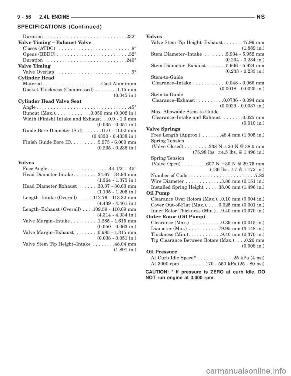
Oil Pump
Clearance Over Rotors (Max.). .0.10 mm (0.004 in.)
Cover Out-of-Flat (Max.).....0.025 mm (0.001 in.)
Inner Rotor Thickness (Min.) . .9.40 mm (0.370 in.)
Outer Rotor (Oil Pump)
Clearance (Max.)...........0.39 mm (0.015 in.)
Diameter (Min.)...........79.95 mm (3.148 in.)
Thickness (Min.)............9.40 mm (0.370 in.)
Tip Clearance Between Rotors (Max.). . . .0.20 mm
(0.008 in.)
Oil Pressure
At Curb Idle Speed*.............25kPa(4psi)
At 3000 rpm.........170 - 550 kPa (25 - 80 psi)
CAUTION: * If pressure is ZERO at curb Idle, DO
NOT run engine at 3,000 rpm.
9 - 56 2.4L ENGINENS
SPECIFICATIONS (Continued)
Page 1111 of 1938
3.0L ENGINE
INDEX
page page
DESCRIPTION AND OPERATION
ENGINE COMPONENTS.................. 61
ENGINE IDENTIFICATION NUMBER......... 61
ENGINE LUBRICATION................... 61
DIAGNOSIS AND TESTING
CHECKING ENGINE OIL PRESSURE......... 62
SERVICE PROCEDURES
AUTO LASH ADJUSTER................... 62
CHECKING CRANKSHAFT END PLAY........ 65
FITTING CONNECTING ROD BEARINGS...... 63
FITTING MAIN BEARING.................. 63
VALVE SERVICE RECONDITION............ 66
REMOVAL AND INSTALLATION
CAMSHAFT SEAL....................... 72
CAMSHAFT............................ 71
CRANKSHAFT.......................... 81
CYLINDER HEAD COVER................. 70
CYLINDER HEAD........................ 73
ENGINE ASSEMBLY...................... 69
ENGINE MOUNTS....................... 68
FRONT CRANKSHAFT OIL SEAL............ 83OIL FILTER AND ADAPTOR................ 84
OILPAN ............................... 77
OIL PUMP............................. 84
PISTON AND CONNECTING ROD........... 78
REAR CRANKSHAFT SEAL................ 83
ROCKER ARMS......................... 72
TIMING BELT........................... 75
DISASSEMBLY AND ASSEMBLY
ROCKER ARMS AND SHAFTS.............. 85
CLEANING AND INSPECTION
CYLINDER BORE........................ 87
CYLINDER HEAD........................ 86
OIL PUMP............................. 87
TIMING BELT........................... 86
ADJUSTMENTS
ENGINE MOUNTS....................... 88
SPECIFICATIONS
3.0L ENGINE........................... 89
TORQUE CHART 3.0L.................... 90
SPECIAL TOOLS
3.0L ENGINE........................... 91
DESCRIPTION AND OPERATION
ENGINE IDENTIFICATION NUMBER
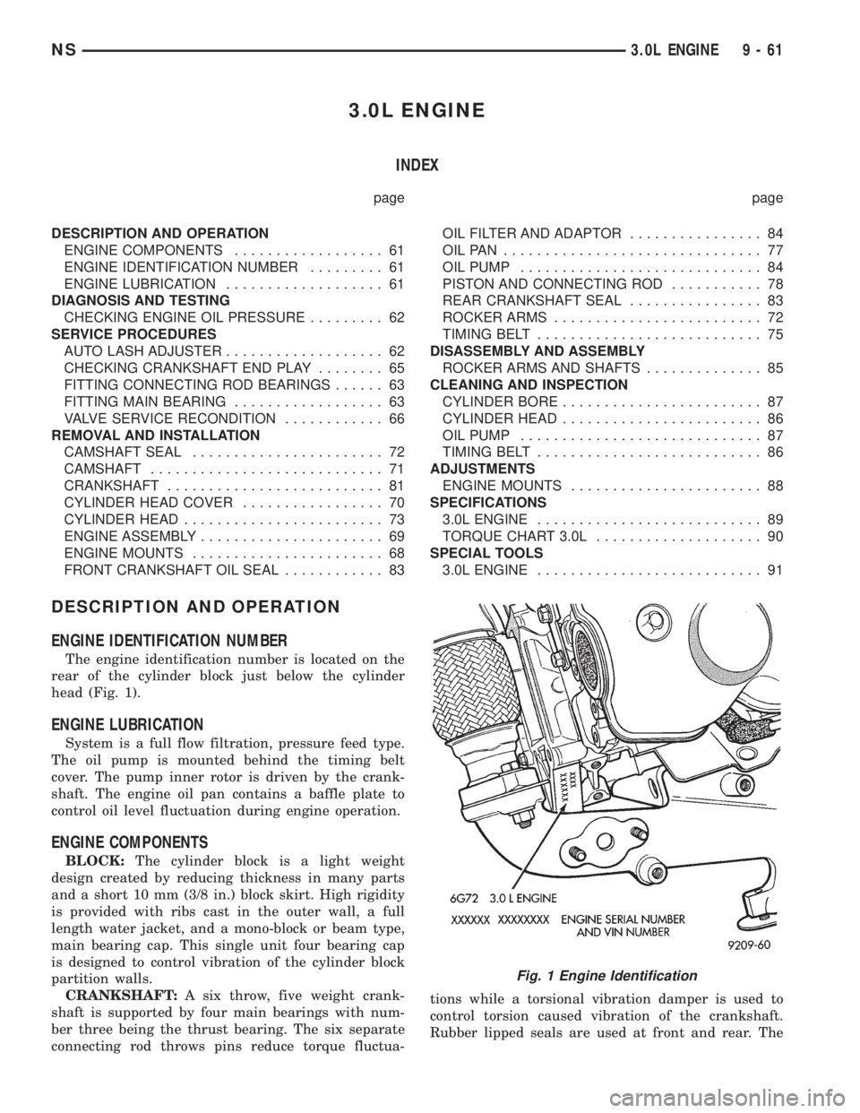
The engine identification number is located on the
rear of the cylinder block just below the cylinder
head (Fig. 1).
ENGINE LUBRICATION
System is a full flow filtration, pressure feed type.
The oil pump is mounted behind the timing belt
cover. The pump inner rotor is driven by the crank-
shaft. The engine oil pan contains a baffle plate to
control oil level fluctuation during engine operation.
ENGINE COMPONENTS
BLOCK:The cylinder block is a light weight
design created by reducing thickness in many parts
and a short 10 mm (3/8 in.) block skirt. High rigidity
is provided with ribs cast in the outer wall, a full
length water jacket, and a mono-block or beam type,
main bearing cap. This single unit four bearing cap
is designed to control vibration of the cylinder block
partition walls.
CRANKSHAFT:A six throw, five weight crank-
shaft is supported by four main bearings with num-
ber three being the thrust bearing. The six separate
connecting rod throws pins reduce torque fluctua-tions while a torsional vibration damper is used to
control torsion caused vibration of the crankshaft.
Rubber lipped seals are used at front and rear. The
Fig. 1 Engine Identification
NS3.0L ENGINE 9 - 61
Page 1113 of 1938
FITTING CONNECTING ROD BEARINGS
CONNECTING ROD CLEARANCE
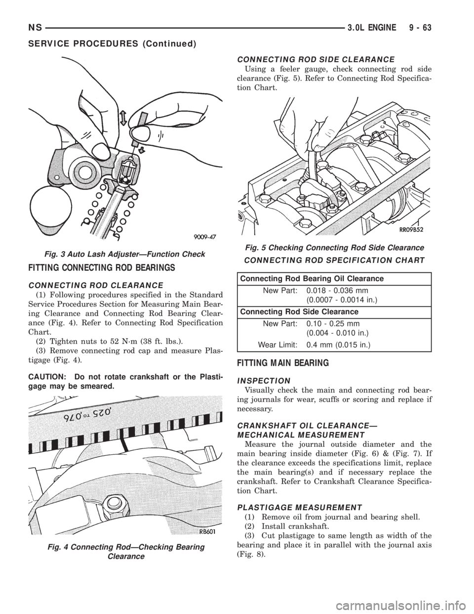
(1) Following procedures specified in the Standard
Service Procedures Section for Measuring Main Bear-
ing Clearance and Connecting Rod Bearing Clear-
ance (Fig. 4). Refer to Connecting Rod Specification
Chart.
(2) Tighten nuts to 52 N´m (38 ft. lbs.).
(3) Remove connecting rod cap and measure Plas-
tigage (Fig. 4).
CAUTION: Do not rotate crankshaft or the Plasti-
gage may be smeared.
CONNECTING ROD SIDE CLEARANCE
Using a feeler gauge, check connecting rod side
clearance (Fig. 5). Refer to Connecting Rod Specifica-
tion Chart.
FITTING MAIN BEARING
INSPECTION
Visually check the main and connecting rod bear-
ing journals for wear, scuffs or scoring and replace if
necessary.
CRANKSHAFT OIL CLEARANCEÐ
MECHANICAL MEASUREMENT
Measure the journal outside diameter and the
main bearing inside diameter (Fig. 6) & (Fig. 7). If
the clearance exceeds the specifications limit, replace
the main bearing(s) and if necessary replace the
crankshaft. Refer to Crankshaft Clearance Specifica-
tion Chart.
PLASTIGAGE MEASUREMENT
(1) Remove oil from journal and bearing shell.
(2) Install crankshaft.
(3) Cut plastigage to same length as width of the
bearing and place it in parallel with the journal axis
(Fig. 8).
Fig. 3 Auto Lash AdjusterÐFunction Check
Fig. 4 Connecting RodÐChecking Bearing
Clearance
Fig. 5 Checking Connecting Rod Side Clearance
CONNECTING ROD SPECIFICATION CHART
Connecting Rod Bearing Oil Clearance
New Part: 0.018 - 0.036 mm
(0.0007 - 0.0014 in.)
Connecting Rod Side Clearance
New Part: 0.10 - 0.25 mm
(0.004 - 0.010 in.)
Wear Limit: 0.4 mm (0.015 in.)
NS3.0L ENGINE 9 - 63
SERVICE PROCEDURES (Continued)
Page 1116 of 1938
VALVE SERVICE RECONDITION
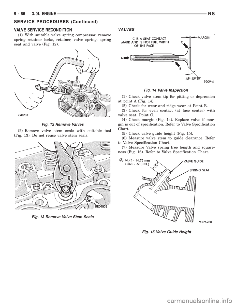
(1) With suitable valve spring compressor, remove
spring retainer locks, retainer, valve spring, spring
seat and valve (Fig. 12).
(2) Remove valve stem seals with suitable tool
(Fig. 13). Do not reuse valve stem seals.
VALVES
(1) Check valve stem tip for pitting or depression
at point A (Fig. 14).
(2) Check for wear and ridge wear at Point B.
(3) Check for even contact (at face center) with
valve seat, Point C.
(4) Check margin (Fig. 14). Replace valve if mar-
gin is out of specification. Refer to Valve Specification
Chart.
(5) Check valve guide height (Fig. 15).
(6) Measure valve stem to guide clearance. Refer
to Valve Specification Chart.
(7) Measure Valve spring free length and square-
ness (Fig. 16). Refer to Valve Specification Chart.
Fig. 12 Remove Valves
Fig. 13 Remove Valve Stem Seals
Fig. 14 Valve Inspection
Fig. 15 Valve Guide Height
9 - 66 3.0L ENGINENS
SERVICE PROCEDURES (Continued)
Page 1117 of 1938
VALVE SEAT
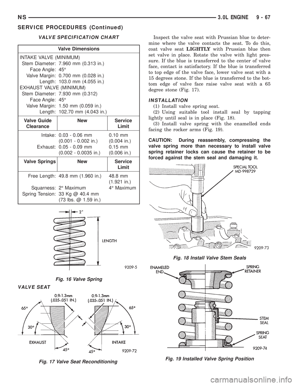
Inspect the valve seat with Prussian blue to deter-
mine where the valve contacts the seat. To do this,
coat valve seatLIGHTLYwith Prussian blue then
set valve in place. Rotate the valve with light pres-
sure. If the blue is transferred to the center of valve
face, contact is satisfactory. If the blue is transferred
to top edge of the valve face, lower valve seat with a
15 degrees stone. If the blue is transferred to the bot-
tom edge of valve face raise valve seat with a 65
degree stone (Fig. 17).
INSTALLATION
(1) Install valve spring seat.
(2) Using suitable tool install seal by tapping
lightly until seal is in place (Fig. 18).
(3) Install valve spring with the enamelled ends
facing the rocker arms (Fig. 19).
CAUTION: During reassembly, compressing the
valve spring more than necessary to install valve
spring retainer locks can cause the retainer to be
forced against the stem seal and damaging it.
VALVE SPECIFICATION CHART
Valve Dimensions
INTAKE VALVE (MINIMUM)
Stem Diameter: 7.960 mm (0.313 in.)
Face Angle: 45É
Valve Margin: 0.700 mm (0.028 in.)
Length: 103.0 mm (4.055 in.)
EXHAUST VALVE (MINIMUM)
Stem Diameter: 7.930 mm (0.312)
Face Angle: 45É
Valve Margin: 1.50 mm (0.059 in.)
Length: 102.70 mm (4.043 in.)
Valve Guide
ClearanceNew Service
Limit
Intake: 0.03 - 0.06 mm
(0.001 - 0.002 in.)0.10 mm
(0.004 in.)
Exhaust: 0.05 - 0.09 mm
(0.002 - 0.0035 in.)0.15 mm
(0.006 in.)
Valve Springs New Service
Limit
Free Length: 49.8 mm (1.960 in.) 48.8 mm
(1.921 in.)
Squarness: 2É Maximum 4É Maximum
Spring Tension: 33 Kg @ 40.4 mm
(73 lbs. @ 1.59 in.)
Fig. 16 Valve Spring
Fig. 17 Valve Seat Reconditioning
Fig. 18 Install Valve Stem Seals
Fig. 19 Installed Valve Spring Position
NS3.0L ENGINE 9 - 67
SERVICE PROCEDURES (Continued)