1996 CHRYSLER VOYAGER fuel injection
[x] Cancel search: fuel injectionPage 1265 of 1938
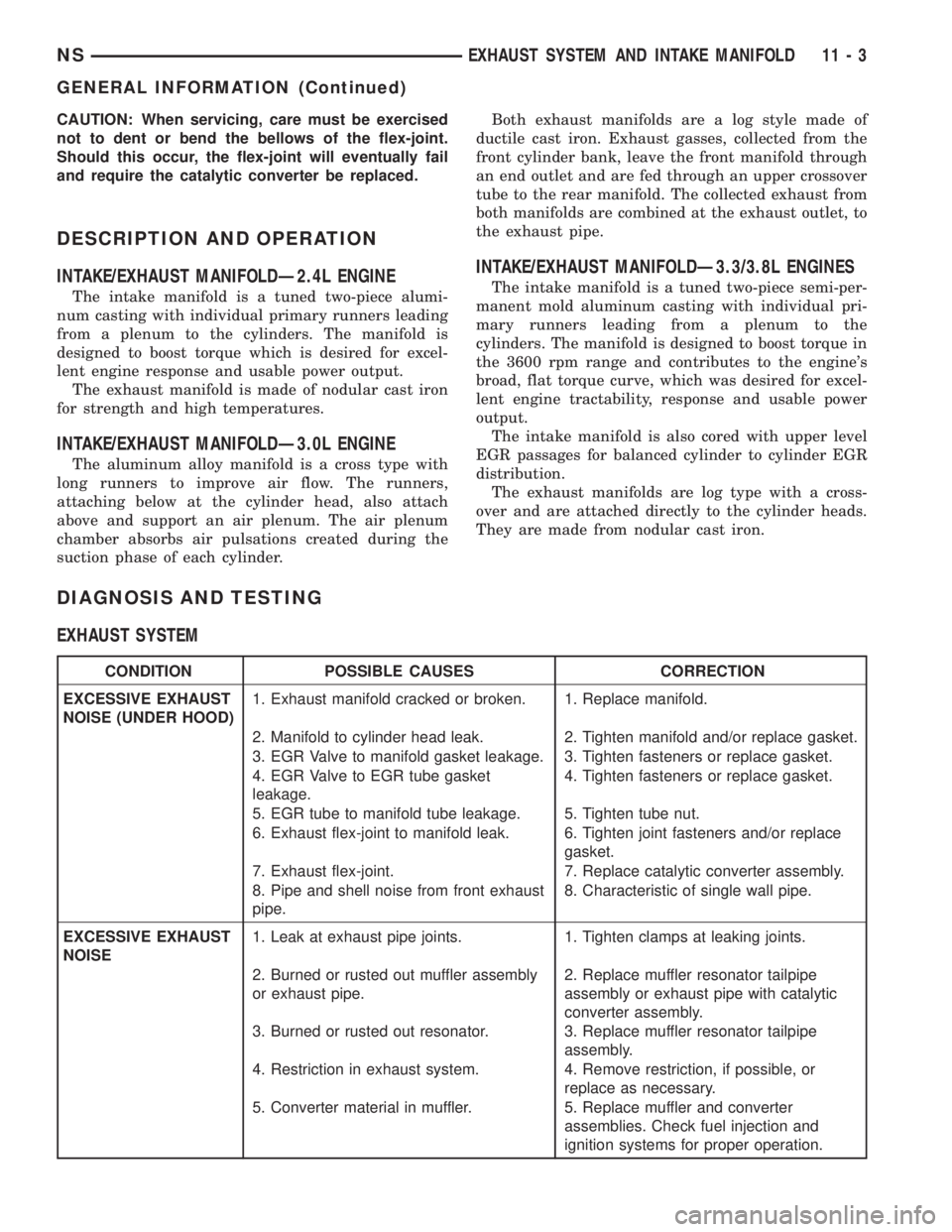
CAUTION: When servicing, care must be exercised
not to dent or bend the bellows of the flex-joint.
Should this occur, the flex-joint will eventually fail
and require the catalytic converter be replaced.
DESCRIPTION AND OPERATION
INTAKE/EXHAUST MANIFOLDÐ2.4L ENGINE
The intake manifold is a tuned two-piece alumi-
num casting with individual primary runners leading
from a plenum to the cylinders. The manifold is
designed to boost torque which is desired for excel-
lent engine response and usable power output.
The exhaust manifold is made of nodular cast iron
for strength and high temperatures.
INTAKE/EXHAUST MANIFOLDÐ3.0L ENGINE
The aluminum alloy manifold is a cross type with
long runners to improve air flow. The runners,
attaching below at the cylinder head, also attach
above and support an air plenum. The air plenum
chamber absorbs air pulsations created during the
suction phase of each cylinder.Both exhaust manifolds are a log style made of
ductile cast iron. Exhaust gasses, collected from the
front cylinder bank, leave the front manifold through
an end outlet and are fed through an upper crossover
tube to the rear manifold. The collected exhaust from
both manifolds are combined at the exhaust outlet, to
the exhaust pipe.
INTAKE/EXHAUST MANIFOLDÐ3.3/3.8L ENGINES
The intake manifold is a tuned two-piece semi-per-
manent mold aluminum casting with individual pri-
mary runners leading from a plenum to the
cylinders. The manifold is designed to boost torque in
the 3600 rpm range and contributes to the engine's
broad, flat torque curve, which was desired for excel-
lent engine tractability, response and usable power
output.
The intake manifold is also cored with upper level
EGR passages for balanced cylinder to cylinder EGR
distribution.
The exhaust manifolds are log type with a cross-
over and are attached directly to the cylinder heads.
They are made from nodular cast iron.
DIAGNOSIS AND TESTING
EXHAUST SYSTEM
CONDITION POSSIBLE CAUSES CORRECTION
EXCESSIVE EXHAUST
NOISE (UNDER HOOD)1. Exhaust manifold cracked or broken. 1. Replace manifold.
2. Manifold to cylinder head leak. 2. Tighten manifold and/or replace gasket.
3. EGR Valve to manifold gasket leakage. 3. Tighten fasteners or replace gasket.
4. EGR Valve to EGR tube gasket
leakage.4. Tighten fasteners or replace gasket.
5. EGR tube to manifold tube leakage. 5. Tighten tube nut.
6. Exhaust flex-joint to manifold leak. 6. Tighten joint fasteners and/or replace
gasket.
7. Exhaust flex-joint. 7. Replace catalytic converter assembly.
8. Pipe and shell noise from front exhaust
pipe.8. Characteristic of single wall pipe.
EXCESSIVE EXHAUST
NOISE1. Leak at exhaust pipe joints. 1. Tighten clamps at leaking joints.
2. Burned or rusted out muffler assembly
or exhaust pipe.2. Replace muffler resonator tailpipe
assembly or exhaust pipe with catalytic
converter assembly.
3. Burned or rusted out resonator. 3. Replace muffler resonator tailpipe
assembly.
4. Restriction in exhaust system. 4. Remove restriction, if possible, or
replace as necessary.
5. Converter material in muffler. 5. Replace muffler and converter
assemblies. Check fuel injection and
ignition systems for proper operation.
NSEXHAUST SYSTEM AND INTAKE MANIFOLD 11 - 3
GENERAL INFORMATION (Continued)
Page 1295 of 1938
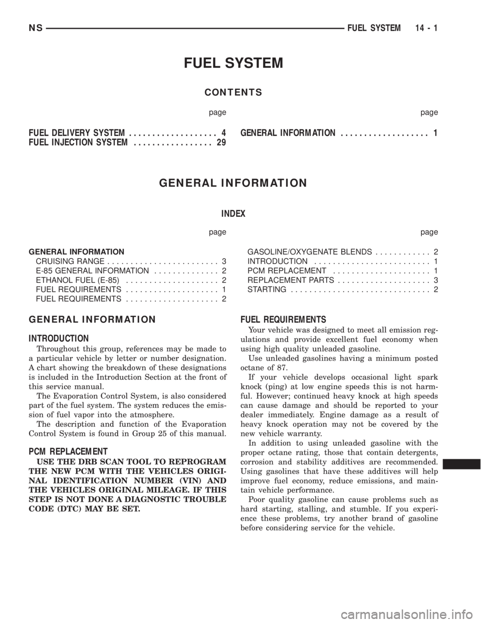
FUEL SYSTEM
CONTENTS
page page
FUEL DELIVERY SYSTEM................... 4
FUEL INJECTION SYSTEM................. 29GENERAL INFORMATION................... 1
GENERAL INFORMATION
INDEX
page page
GENERAL INFORMATION
CRUISING RANGE........................ 3
E-85 GENERAL INFORMATION.............. 2
ETHANOL FUEL (E-85).................... 2
FUEL REQUIREMENTS.................... 1
FUEL REQUIREMENTS.................... 2GASOLINE/OXYGENATE BLENDS............ 2
INTRODUCTION......................... 1
PCM REPLACEMENT..................... 1
REPLACEMENT PARTS.................... 3
STARTING.............................. 2
GENERAL INFORMATION
INTRODUCTION
Throughout this group, references may be made to
a particular vehicle by letter or number designation.
A chart showing the breakdown of these designations
is included in the Introduction Section at the front of
this service manual.
The Evaporation Control System, is also considered
part of the fuel system. The system reduces the emis-
sion of fuel vapor into the atmosphere.
The description and function of the Evaporation
Control System is found in Group 25 of this manual.
PCM REPLACEMENT
USE THE DRB SCAN TOOL TO REPROGRAM
THE NEW PCM WITH THE VEHICLES ORIGI-
NAL IDENTIFICATION NUMBER (VIN) AND
THE VEHICLES ORIGINAL MILEAGE. IF THIS
STEP IS NOT DONE A DIAGNOSTIC TROUBLE
CODE (DTC) MAY BE SET.
FUEL REQUIREMENTS
Your vehicle was designed to meet all emission reg-
ulations and provide excellent fuel economy when
using high quality unleaded gasoline.
Use unleaded gasolines having a minimum posted
octane of 87.
If your vehicle develops occasional light spark
knock (ping) at low engine speeds this is not harm-
ful. However; continued heavy knock at high speeds
can cause damage and should be reported to your
dealer immediately. Engine damage as a result of
heavy knock operation may not be covered by the
new vehicle warranty.
In addition to using unleaded gasoline with the
proper octane rating, those that contain detergents,
corrosion and stability additives are recommended.
Using gasolines that have these additives will help
improve fuel economy, reduce emissions, and main-
tain vehicle performance.
Poor quality gasoline can cause problems such as
hard starting, stalling, and stumble. If you experi-
ence these problems, try another brand of gasoline
before considering service for the vehicle.
NSFUEL SYSTEM 14 - 1
Page 1323 of 1938
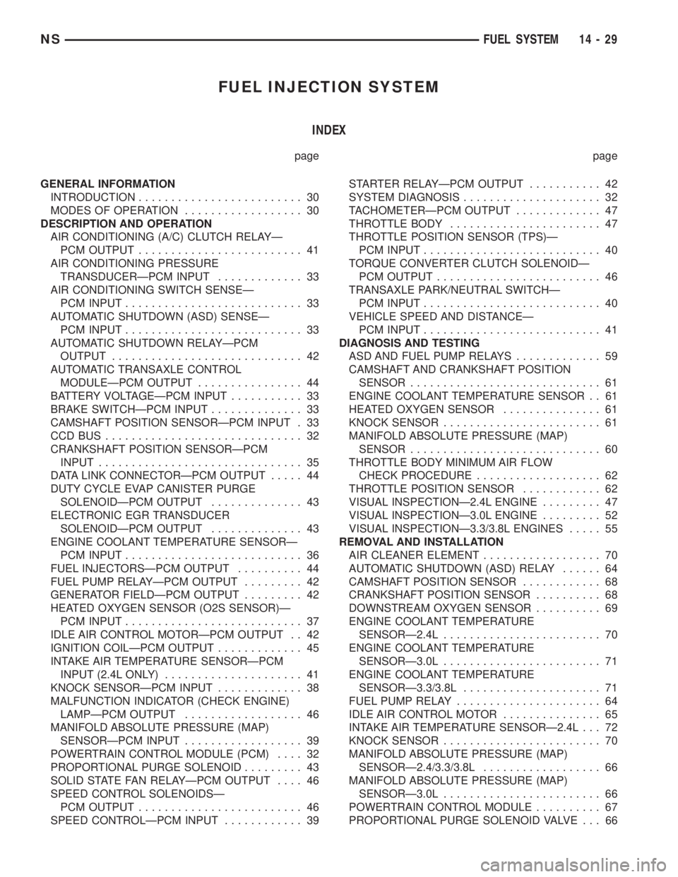
FUEL INJECTION SYSTEM
INDEX
page page
GENERAL INFORMATION
INTRODUCTION......................... 30
MODES OF OPERATION.................. 30
DESCRIPTION AND OPERATION
AIR CONDITIONING (A/C) CLUTCH RELAYÐ
PCM OUTPUT......................... 41
AIR CONDITIONING PRESSURE
TRANSDUCERÐPCM INPUT............. 33
AIR CONDITIONING SWITCH SENSEÐ
PCM INPUT........................... 33
AUTOMATIC SHUTDOWN (ASD) SENSEÐ
PCM INPUT........................... 33
AUTOMATIC SHUTDOWN RELAYÐPCM
OUTPUT............................. 42
AUTOMATIC TRANSAXLE CONTROL
MODULEÐPCM OUTPUT................ 44
BATTERY VOLTAGEÐPCM INPUT........... 33
BRAKE SWITCHÐPCM INPUT.............. 33
CAMSHAFT POSITION SENSORÐPCM INPUT . 33
CCDBUS .............................. 32
CRANKSHAFT POSITION SENSORÐPCM
INPUT............................... 35
DATA LINK CONNECTORÐPCM OUTPUT..... 44
DUTY CYCLE EVAP CANISTER PURGE
SOLENOIDÐPCM OUTPUT.............. 43
ELECTRONIC EGR TRANSDUCER
SOLENOIDÐPCM OUTPUT.............. 43
ENGINE COOLANT TEMPERATURE SENSORÐ
PCM INPUT........................... 36
FUEL INJECTORSÐPCM OUTPUT.......... 44
FUEL PUMP RELAYÐPCM OUTPUT......... 42
GENERATOR FIELDÐPCM OUTPUT......... 42
HEATED OXYGEN SENSOR (O2S SENSOR)Ð
PCM INPUT........................... 37
IDLE AIR CONTROL MOTORÐPCM OUTPUT . . 42
IGNITION COILÐPCM OUTPUT............. 45
INTAKE AIR TEMPERATURE SENSORÐPCM
INPUT (2.4L ONLY)..................... 41
KNOCK SENSORÐPCM INPUT............. 38
MALFUNCTION INDICATOR (CHECK ENGINE)
LAMPÐPCM OUTPUT.................. 46
MANIFOLD ABSOLUTE PRESSURE (MAP)
SENSORÐPCM INPUT.................. 39
POWERTRAIN CONTROL MODULE (PCM).... 32
PROPORTIONAL PURGE SOLENOID......... 43
SOLID STATE FAN RELAYÐPCM OUTPUT.... 46
SPEED CONTROL SOLENOIDSÐ
PCM OUTPUT......................... 46
SPEED CONTROLÐPCM INPUT............ 39STARTER RELAYÐPCM OUTPUT........... 42
SYSTEM DIAGNOSIS..................... 32
TACHOMETERÐPCM OUTPUT............. 47
THROTTLE BODY....................... 47
THROTTLE POSITION SENSOR (TPS)Ð
PCM INPUT........................... 40
TORQUE CONVERTER CLUTCH SOLENOIDÐ
PCM OUTPUT......................... 46
TRANSAXLE PARK/NEUTRAL SWITCHÐ
PCM INPUT........................... 40
VEHICLE SPEED AND DISTANCEÐ
PCM INPUT........................... 41
DIAGNOSIS AND TESTING
ASD AND FUEL PUMP RELAYS............. 59
CAMSHAFT AND CRANKSHAFT POSITION
SENSOR............................. 61
ENGINE COOLANT TEMPERATURE SENSOR . . 61
HEATED OXYGEN SENSOR............... 61
KNOCK SENSOR........................ 61
MANIFOLD ABSOLUTE PRESSURE (MAP)
SENSOR............................. 60
THROTTLE BODY MINIMUM AIR FLOW
CHECK PROCEDURE................... 62
THROTTLE POSITION SENSOR............ 62
VISUAL INSPECTIONÐ2.4L ENGINE......... 47
VISUAL INSPECTIONÐ3.0L ENGINE......... 52
VISUAL INSPECTIONÐ3.3/3.8L ENGINES..... 55
REMOVAL AND INSTALLATION
AIR CLEANER ELEMENT.................. 70
AUTOMATIC SHUTDOWN (ASD) RELAY...... 64
CAMSHAFT POSITION SENSOR............ 68
CRANKSHAFT POSITION SENSOR.......... 68
DOWNSTREAM OXYGEN SENSOR.......... 69
ENGINE COOLANT TEMPERATURE
SENSORÐ2.4L........................ 70
ENGINE COOLANT TEMPERATURE
SENSORÐ3.0L........................ 71
ENGINE COOLANT TEMPERATURE
SENSORÐ3.3/3.8L..................... 71
FUEL PUMP RELAY...................... 64
IDLE AIR CONTROL MOTOR............... 65
INTAKE AIR TEMPERATURE SENSORÐ2.4L . . . 72
KNOCK SENSOR........................ 70
MANIFOLD ABSOLUTE PRESSURE (MAP)
SENSORÐ2.4/3.3/3.8L.................. 66
MANIFOLD ABSOLUTE PRESSURE (MAP)
SENSORÐ3.0L........................ 66
POWERTRAIN CONTROL MODULE.......... 67
PROPORTIONAL PURGE SOLENOID VALVE . . . 66
NSFUEL SYSTEM 14 - 29
Page 1324 of 1938
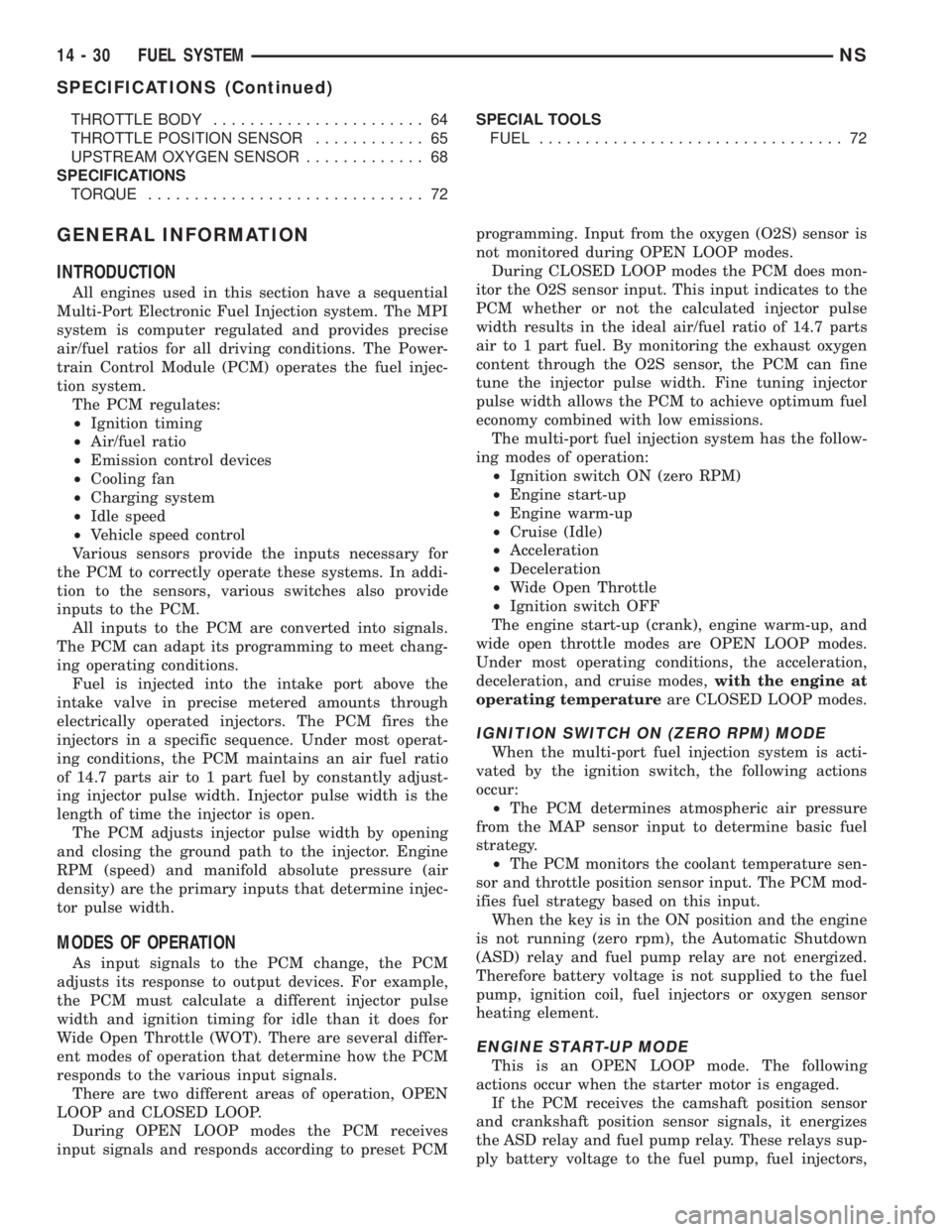
THROTTLE BODY....................... 64
THROTTLE POSITION SENSOR............ 65
UPSTREAM OXYGEN SENSOR............. 68
SPECIFICATIONS
TORQUE.............................. 72SPECIAL TOOLS
FUEL................................. 72
GENERAL INFORMATION
INTRODUCTION
All engines used in this section have a sequential
Multi-Port Electronic Fuel Injection system. The MPI
system is computer regulated and provides precise
air/fuel ratios for all driving conditions. The Power-
train Control Module (PCM) operates the fuel injec-
tion system.
The PCM regulates:
²Ignition timing
²Air/fuel ratio
²Emission control devices
²Cooling fan
²Charging system
²Idle speed
²Vehicle speed control
Various sensors provide the inputs necessary for
the PCM to correctly operate these systems. In addi-
tion to the sensors, various switches also provide
inputs to the PCM.
All inputs to the PCM are converted into signals.
The PCM can adapt its programming to meet chang-
ing operating conditions.
Fuel is injected into the intake port above the
intake valve in precise metered amounts through
electrically operated injectors. The PCM fires the
injectors in a specific sequence. Under most operat-
ing conditions, the PCM maintains an air fuel ratio
of 14.7 parts air to 1 part fuel by constantly adjust-
ing injector pulse width. Injector pulse width is the
length of time the injector is open.
The PCM adjusts injector pulse width by opening
and closing the ground path to the injector. Engine
RPM (speed) and manifold absolute pressure (air
density) are the primary inputs that determine injec-
tor pulse width.
MODES OF OPERATION
As input signals to the PCM change, the PCM
adjusts its response to output devices. For example,
the PCM must calculate a different injector pulse
width and ignition timing for idle than it does for
Wide Open Throttle (WOT). There are several differ-
ent modes of operation that determine how the PCM
responds to the various input signals.
There are two different areas of operation, OPEN
LOOP and CLOSED LOOP.
During OPEN LOOP modes the PCM receives
input signals and responds according to preset PCMprogramming. Input from the oxygen (O2S) sensor is
not monitored during OPEN LOOP modes.
During CLOSED LOOP modes the PCM does mon-
itor the O2S sensor input. This input indicates to the
PCM whether or not the calculated injector pulse
width results in the ideal air/fuel ratio of 14.7 parts
air to 1 part fuel. By monitoring the exhaust oxygen
content through the O2S sensor, the PCM can fine
tune the injector pulse width. Fine tuning injector
pulse width allows the PCM to achieve optimum fuel
economy combined with low emissions.
The multi-port fuel injection system has the follow-
ing modes of operation:
²Ignition switch ON (zero RPM)
²Engine start-up
²Engine warm-up
²Cruise (Idle)
²Acceleration
²Deceleration
²Wide Open Throttle
²Ignition switch OFF
The engine start-up (crank), engine warm-up, and
wide open throttle modes are OPEN LOOP modes.
Under most operating conditions, the acceleration,
deceleration, and cruise modes,with the engine at
operating temperatureare CLOSED LOOP modes.
IGNITION SWITCH ON (ZERO RPM) MODE
When the multi-port fuel injection system is acti-
vated by the ignition switch, the following actions
occur:
²The PCM determines atmospheric air pressure
from the MAP sensor input to determine basic fuel
strategy.
²The PCM monitors the coolant temperature sen-
sor and throttle position sensor input. The PCM mod-
ifies fuel strategy based on this input.
When the key is in the ON position and the engine
is not running (zero rpm), the Automatic Shutdown
(ASD) relay and fuel pump relay are not energized.
Therefore battery voltage is not supplied to the fuel
pump, ignition coil, fuel injectors or oxygen sensor
heating element.
ENGINE START-UP MODE
This is an OPEN LOOP mode. The following
actions occur when the starter motor is engaged.
If the PCM receives the camshaft position sensor
and crankshaft position sensor signals, it energizes
the ASD relay and fuel pump relay. These relays sup-
ply battery voltage to the fuel pump, fuel injectors,
14 - 30 FUEL SYSTEMNS
SPECIFICATIONS (Continued)
Page 1327 of 1938
²Engine coolant temperature
²Engine speed (crankshaft position sensor)
²Intake air temperature (2.4L only)
²Manifold absolute pressure
²Throttle position
²Transaxle gear selection (park/neutral switch)
The PCM also adjusts engine idle speed through
the idle air control motor based on the following
inputs.
²Air conditioning select switch head pressure
²Brake switch
²Engine coolant temperature
²Engine speed (crankshaft position sensor)
²Manifold absolute pressure
²Throttle position
²Transaxle gear selection (park/neutral switch)
²Vehicle distance (speed)
The Automatic Shutdown (ASD) and fuel pump
relays are located in the Power Distribution Center
(PDC).
The camshaft position sensor (distributor pick-up
signal 3.0L) and crankshaft position sensor signals
are sent to the PCM. If the PCM does not receive
both signals within approximately one second of
engine cranking, it deactivates the ASD relay and
fuel pump relay. When these relays are deactivated,
power is shut off to the fuel injectors, ignition coil,
oxygen sensor heating element and fuel pump.
The PCM contains a voltage converter that
changes battery voltage to a regulated 8.0 volts to
power the camshaft position sensor, crankshaft posi-
tion sensor and vehicle speed sensor. The PCM also
provides a 5.0 volt supply for the manifold absolute
pressure sensor, throttle position sensor and engine
coolant temperature sensor.
AIR CONDITIONING PRESSURE TRANSDUCERÐ
PCM INPUT
The Powertrain Control Module (PCM) monitors
the A/C compressor discharge (high side) pressure
through the air conditioning pressure transducer.
The transducer supplies an input to the PCM. The
PCM engages the A/C compressor clutch if pressure
is sufficient for A/C system operation.
AIR CONDITIONING SWITCH SENSEÐPCM INPUT
When the air conditioning or defrost switch is put
in the ON position and the low pressure switch, com-
bination valve, and high pressure switch close, the
PCM receives an A/C input. After receiving this
input, the PCM activates the A/C compressor clutch
by grounding the A/C clutch relay. The PCM also
adjusts idle speed to a scheduled RPM to compensate
for increased engine load.
AUTOMATIC SHUTDOWN (ASD) SENSEÐPCM
INPUT
The ASD sense circuit informs the PCM when the
ASD relay energizes. A 12 volt signal at this input
indicates to the PCM that the ASD has been acti-
vated. This input is used only to sense that the ASD
relay is energized.
When energized, the ASD relay supplies battery
voltage to the fuel injectors, ignition coils and the
heating element in each oxygen sensor. If the PCM
does not receive 12 volts from this input after
grounding the ASD relay, it sets a Diagnostic Trouble
Code (DTC).
BATTERY VOLTAGEÐPCM INPUT
The PCM monitors the battery voltage input to
determine fuel injector pulse width and generator
field control.
If battery voltage is low the PCM will increase
injector pulse width (period of time that the injector
is energized).
BRAKE SWITCHÐPCM INPUT
When the brake switch is activated, the PCM
receives an input indicating that the brakes are
being applied. After receiving this input the PCM
maintains idle speed to a scheduled RPM through
control of the idle air control motor. The brake switch
is mounted on the brake pedal support bracket.
CAMSHAFT POSITION SENSORÐPCM INPUT
The PCM determines fuel injection synchronization
and cylinder identification from inputs provided by
the camshaft position sensor and crankshaft position
sensor. From the two inputs, the PCM determines
crankshaft position.
3.3/3.8L
The sensor generates pulses as groups of notches
on the camshaft sprocket pass underneath it (Fig. 2).
The PCM keeps track of crankshaft rotation and
identifies each cylinder by the pulses generated by
the notches on the camshaft sprocket. Four crank-
shaft pulses follow each group of camshaft pulses.
When the PCM receives two camshaft pulses fol-
lowed by the long flat spot on the camshaft sprocket,
it knows that the crankshaft timing marks for cylin-
der one are next (on driveplate). When the PCM
receives one camshaft pulse after the long flat spot
on the sprocket, cylinder number two crankshaft tim-
ing marks are next. After 3 camshaft pulses, the
PCM knows cylinder four crankshaft timing marks
follow. One camshaft pulse after the three pulses
indicates cylinder five. The two camshaft pulses after
cylinder 5 signals cylinder six (Fig. 3). The PCM can
synchronize on cylinders 1 or 4.
NSFUEL SYSTEM 14 - 33
DESCRIPTION AND OPERATION (Continued)
Page 1328 of 1938
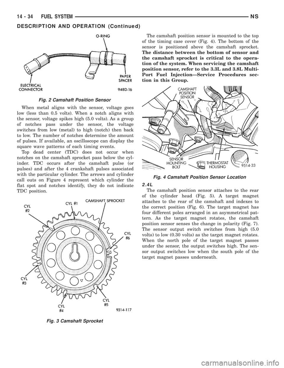
When metal aligns with the sensor, voltage goes
low (less than 0.5 volts). When a notch aligns with
the sensor, voltage spikes high (5.0 volts). As a group
of notches pass under the sensor, the voltage
switches from low (metal) to high (notch) then back
to low. The number of notches determine the amount
of pulses. If available, an oscilloscope can display the
square wave patterns of each timing events.
Top dead center (TDC) does not occur when
notches on the camshaft sprocket pass below the cyl-
inder. TDC occurs after the camshaft pulse (or
pulses) and after the 4 crankshaft pulses associated
with the particular cylinder. The arrows and cylinder
call outs on Figure 4 represent which cylinder the
flat spot and notches identify, they do not indicate
TDC position.The camshaft position sensor is mounted to the top
of the timing case cover (Fig. 4). The bottom of the
sensor is positioned above the camshaft sprocket.
The distance between the bottom of sensor and
the camshaft sprocket is critical to the opera-
tion of the system. When servicing the camshaft
position sensor, refer to the 3.3L and 3.8L Multi-
Port Fuel InjectionÐService Procedures sec-
tion in this Group.
2.4L
The camshaft position sensor attaches to the rear
of the cylinder head (Fig. 5). A target magnet
attaches to the rear of the camshaft and indexes to
the correct position (Fig. 6). The target magnet has
four different poles arranged in an asymmetrical pat-
tern. As the target magnet rotates, the camshaft
position sensor senses the change in polarity (Fig. 7).
The sensor output switch switches from high (5.0
volts) to low (0.30 volts) as the target magnet rotates.
When the north pole of the target magnet passes
under the sensor, the output switches high. The sen-
sor output switches low when the south pole of the
target magnet passes underneath.
Fig. 2 Camshaft Position Sensor
Fig. 3 Camshaft Sprocket
Fig. 4 Camshaft Position Sensor Location
14 - 34 FUEL SYSTEMNS
DESCRIPTION AND OPERATION (Continued)
Page 1330 of 1938
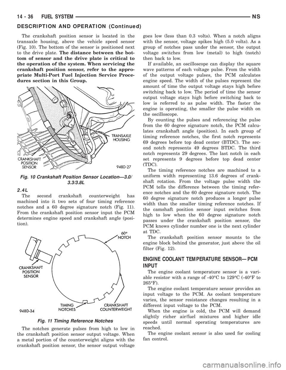
The crankshaft position sensor is located in the
transaxle housing, above the vehicle speed sensor
(Fig. 10). The bottom of the sensor is positioned next
to the drive plate.The distance between the bot-
tom of sensor and the drive plate is critical to
the operation of the system. When servicing the
crankshaft position sensor, refer to the appro-
priate Multi-Port Fuel Injection Service Proce-
dures section in this Group.
2.4L
The second crankshaft counterweight has
machined into it two sets of four timing reference
notches and a 60 degree signature notch (Fig. 11).
From the crankshaft position sensor input the PCM
determines engine speed and crankshaft angle (posi-
tion).
The notches generate pulses from high to low in
the crankshaft position sensor output voltage. When
a metal portion of the counterweight aligns with the
crankshaft position sensor, the sensor output voltagegoes low (less than 0.3 volts). When a notch aligns
with the sensor, voltage spikes high (5.0 volts). As a
group of notches pass under the sensor, the output
voltage switches from low (metal) to high (notch)
then back to low.
If available, an oscilloscope can display the square
wave patterns of each voltage pulse. From the width
of the output voltage pulses, the PCM calculates
engine speed. The width of the pulses represent the
amount of time the output voltage stays high before
switching back to low. The period of time the sensor
output voltage stays high before switching back to
low is referred to as pulse width. The faster the
engine is operating, the smaller the pulse width on
the oscilloscope.
By counting the pulses and referencing the pulse
from the 60 degree signature notch, the PCM calcu-
lates crankshaft angle (position). In each group of
timing reference notches, the first notch represents
69 degrees before top dead center (BTDC). The sec-
ond notch represents 49 degrees BTDC. The third
notch represents 29 degrees. The last notch in each
set represents 9 degrees before top dead center
(TDC).
The timing reference notches are machined to a
uniform width representing 13.6 degrees of crank-
shaft rotation. From the voltage pulse width the
PCM tells the difference between the timing refer-
ence notches and the 60 degree signature notch. The
60 degree signature notch produces a longer pulse
width than the smaller timing reference notches. If
the camshaft position sensor input switches from
high to low when the 60 degree signature notch
passes under the crankshaft position sensor, the
PCM knows cylinder number one is the next cylinder
at TDC.
The crankshaft position sensor mounts to the
engine block behind the generator, just above the oil
filter (Fig. 12).
ENGINE COOLANT TEMPERATURE SENSORÐPCM
INPUT
The engine coolant temperature sensor is a vari-
able resistor with a range of -40ÉC to 129ÉC (-40ÉF to
265ÉF).
The engine coolant temperature sensor provides an
input voltage to the PCM. As coolant temperature
varies, the sensor resistance changes resulting in a
different input voltage to the PCM.
When the engine is cold, the PCM will demand
slightly richer air/fuel mixtures and higher idle
speeds until normal operating temperatures are
reached.
The engine coolant sensor is also used for cooling
fan control.
Fig. 10 Crankshaft Position Sensor LocationÐ3.0/
3.3/3.8L
Fig. 11 Timing Reference Notches
14 - 36 FUEL SYSTEMNS
DESCRIPTION AND OPERATION (Continued)
Page 1341 of 1938
ances the two solenoids to maintain the set speed.
Refer to Group 8H for speed control information.
TACHOMETERÐPCM OUTPUT
The PCM supplies engine RPM to the instrument
panel tachometer through the CCD Bus. The CCD
Bus is a communications port. Various modules use
the CCD Bus to exchange information. Refer to
Group 8E for more information.
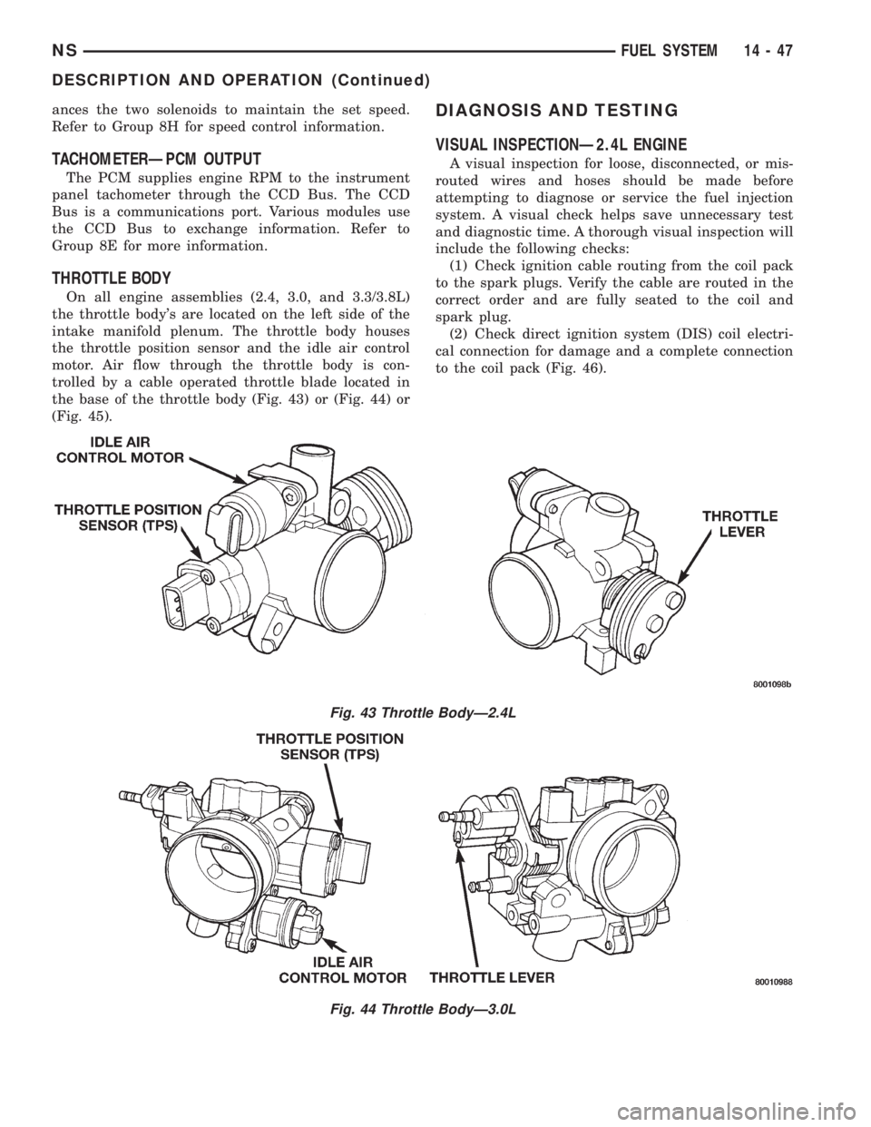
THROTTLE BODY
On all engine assemblies (2.4, 3.0, and 3.3/3.8L)
the throttle body's are located on the left side of the
intake manifold plenum. The throttle body houses
the throttle position sensor and the idle air control
motor. Air flow through the throttle body is con-
trolled by a cable operated throttle blade located in
the base of the throttle body (Fig. 43) or (Fig. 44) or
(Fig. 45).
DIAGNOSIS AND TESTING
VISUAL INSPECTIONÐ2.4L ENGINE
A visual inspection for loose, disconnected, or mis-
routed wires and hoses should be made before
attempting to diagnose or service the fuel injection
system. A visual check helps save unnecessary test
and diagnostic time. A thorough visual inspection will
include the following checks:
(1) Check ignition cable routing from the coil pack
to the spark plugs. Verify the cable are routed in the
correct order and are fully seated to the coil and
spark plug.
(2) Check direct ignition system (DIS) coil electri-
cal connection for damage and a complete connection
to the coil pack (Fig. 46).
Fig. 43 Throttle BodyÐ2.4L
Fig. 44 Throttle BodyÐ3.0L
NSFUEL SYSTEM 14 - 47
DESCRIPTION AND OPERATION (Continued)