1996 CHRYSLER VOYAGER fuel injection
[x] Cancel search: fuel injectionPage 1385 of 1938
WARNING: DO NOT ATTEMPT TO DRAIN WATER
FROM THE FILTER/SEPARATOR WITH THE ENGINE
HOT.
(1) The bottom of the filter/separator bowl is
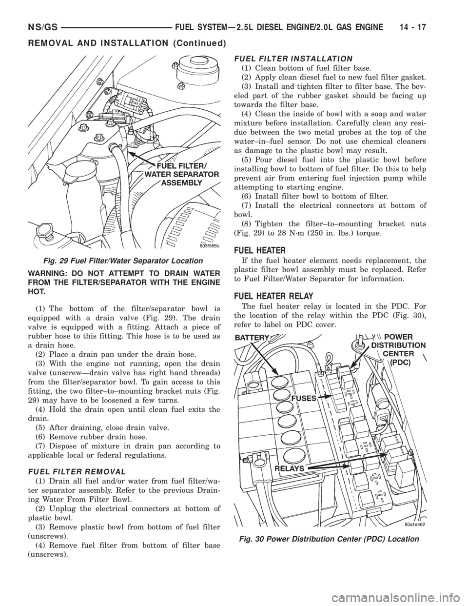
equipped with a drain valve (Fig. 29). The drain
valve is equipped with a fitting. Attach a piece of
rubber hose to this fitting. This hose is to be used as
a drain hose.
(2) Place a drain pan under the drain hose.
(3) With the engine not running, open the drain
valve (unscrewÐdrain valve has right hand threads)
from the filter/separator bowl. To gain access to this
fitting, the two filter±to±mounting bracket nuts (Fig.
29) may have to be loosened a few turns.
(4) Hold the drain open until clean fuel exits the
drain.
(5) After draining, close drain valve.
(6) Remove rubber drain hose.
(7) Dispose of mixture in drain pan according to
applicable local or federal regulations.
FUEL FILTER REMOVAL
(1) Drain all fuel and/or water from fuel filter/wa-
ter separator assembly. Refer to the previous Drain-
ing Water From Filter Bowl.
(2) Unplug the electrical connectors at bottom of
plastic bowl.
(3) Remove plastic bowl from bottom of fuel filter
(unscrews).
(4) Remove fuel filter from bottom of filter base
(unscrews).
FUEL FILTER INSTALLATION
(1) Clean bottom of fuel filter base.
(2) Apply clean diesel fuel to new fuel filter gasket.
(3) Install and tighten filter to filter base. The bev-
eled part of the rubber gasket should be facing up
towards the filter base.
(4) Clean the inside of bowl with a soap and water
mixture before installation. Carefully clean any resi-
due between the two metal probes at the top of the
water±in±fuel sensor. Do not use chemical cleaners
as damage to the plastic bowl may result.
(5) Pour diesel fuel into the plastic bowl before
installing bowl to bottom of fuel filter. Do this to help
prevent air from entering fuel injection pump while
attempting to starting engine.
(6) Install filter bowl to bottom of filter.
(7) Install the electrical connectors at bottom of
bowl.
(8) Tighten the filter±to±mounting bracket nuts
(Fig. 29) to 28 N´m (250 in. lbs.) torque.
FUEL HEATER
If the fuel heater element needs replacement, the
plastic filter bowl assembly must be replaced. Refer
to Fuel Filter/Water Separator for information.
FUEL HEATER RELAY
The fuel heater relay is located in the PDC. For
the location of the relay within the PDC (Fig. 30),
refer to label on PDC cover.
Fig. 29 Fuel Filter/Water Separator Location
Fig. 30 Power Distribution Center (PDC) Location
NS/GSFUEL SYSTEMÐ2.5L DIESEL ENGINE/2.0L GAS ENGINE 14 - 17
REMOVAL AND INSTALLATION (Continued)
Page 1387 of 1938
INSTALLATION
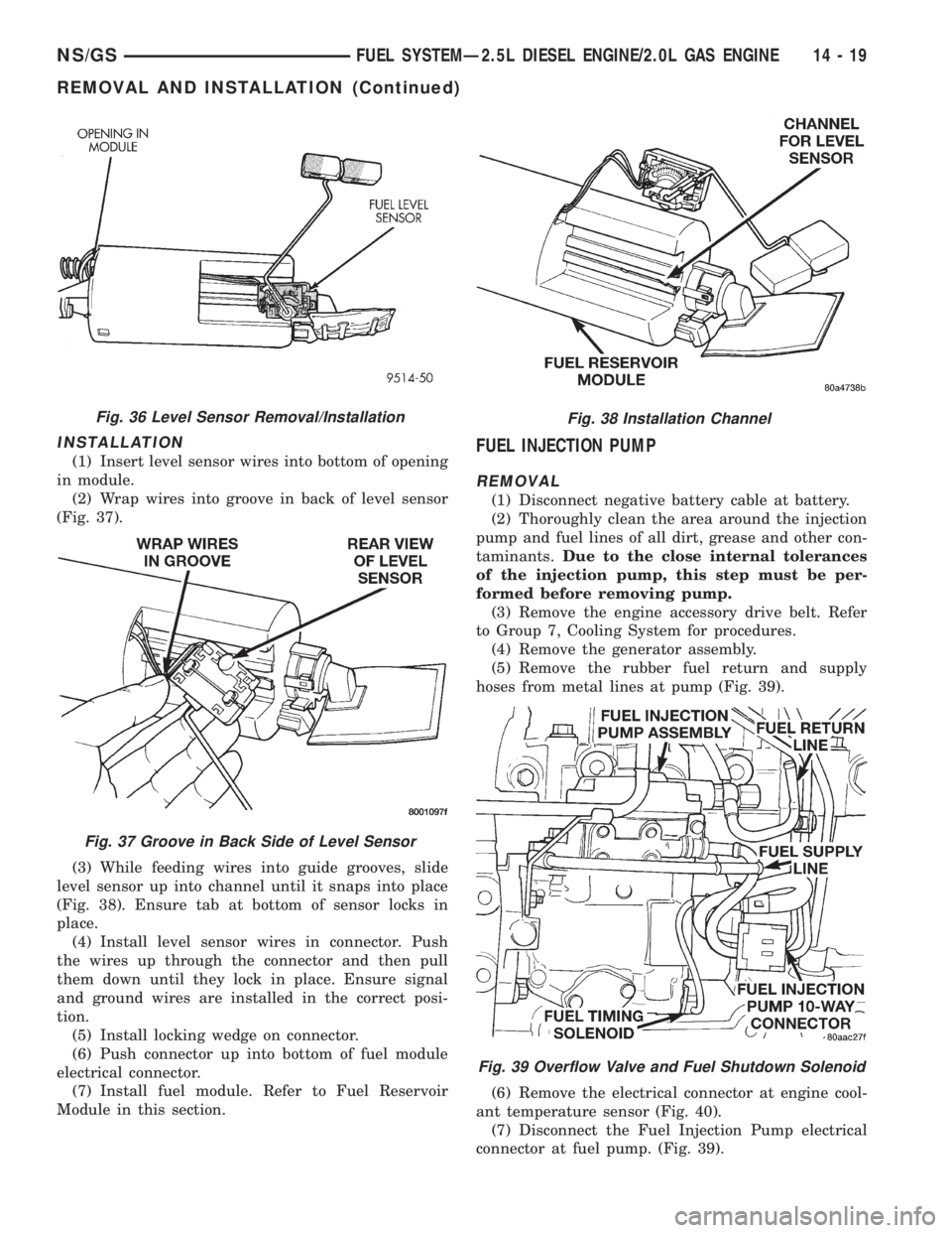
(1) Insert level sensor wires into bottom of opening
in module.
(2) Wrap wires into groove in back of level sensor
(Fig. 37).
(3) While feeding wires into guide grooves, slide
level sensor up into channel until it snaps into place
(Fig. 38). Ensure tab at bottom of sensor locks in
place.
(4) Install level sensor wires in connector. Push
the wires up through the connector and then pull
them down until they lock in place. Ensure signal
and ground wires are installed in the correct posi-
tion.
(5) Install locking wedge on connector.
(6) Push connector up into bottom of fuel module
electrical connector.
(7) Install fuel module. Refer to Fuel Reservoir
Module in this section.FUEL INJECTION PUMP
REMOVAL
(1) Disconnect negative battery cable at battery.
(2) Thoroughly clean the area around the injection
pump and fuel lines of all dirt, grease and other con-
taminants.Due to the close internal tolerances
of the injection pump, this step must be per-
formed before removing pump.
(3) Remove the engine accessory drive belt. Refer
to Group 7, Cooling System for procedures.
(4) Remove the generator assembly.
(5) Remove the rubber fuel return and supply
hoses from metal lines at pump (Fig. 39).
(6) Remove the electrical connector at engine cool-
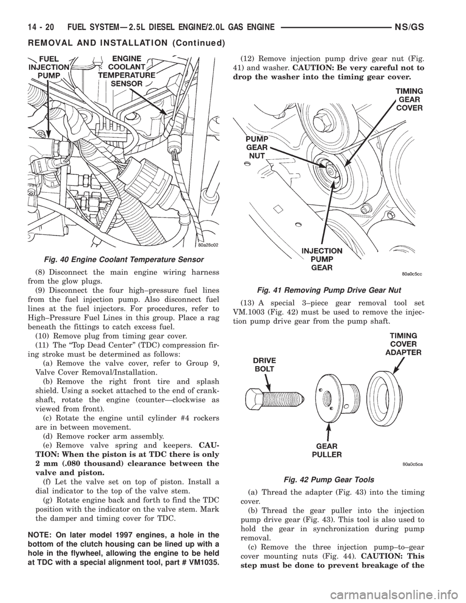
ant temperature sensor (Fig. 40).
(7) Disconnect the Fuel Injection Pump electrical
connector at fuel pump. (Fig. 39).
Fig. 36 Level Sensor Removal/Installation
Fig. 37 Groove in Back Side of Level Sensor
Fig. 38 Installation Channel
Fig. 39 Overflow Valve and Fuel Shutdown Solenoid
NS/GSFUEL SYSTEMÐ2.5L DIESEL ENGINE/2.0L GAS ENGINE 14 - 19
REMOVAL AND INSTALLATION (Continued)
Page 1388 of 1938
(8) Disconnect the main engine wiring harness
from the glow plugs.
(9) Disconnect the four high±pressure fuel lines
from the fuel injection pump. Also disconnect fuel
lines at the fuel injectors. For procedures, refer to
High±Pressure Fuel Lines in this group. Place a rag
beneath the fittings to catch excess fuel.
(10) Remove plug from timing gear cover.
(11) The ªTop Dead Centerº (TDC) compression fir-
ing stroke must be determined as follows:
(a) Remove the valve cover, refer to Group 9,
Valve Cover Removal/Installation.
(b) Remove the right front tire and splash
shield. Using a socket attached to the end of crank-
shaft, rotate the engine (counterÐclockwise as
viewed from front).
(c) Rotate the engine until cylinder #4 rockers
are in between movement.
(d) Remove rocker arm assembly.
(e) Remove valve spring and keepers.CAU-
TION: When the piston is at TDC there is only
2 mm (.080 thousand) clearance between the
valve and piston.
(f) Let the valve set on top of piston. Install a
dial indicator to the top of the valve stem.
(g) Rotate engine back and forth to find the TDC
position with the indicator on the valve stem. Mark
the damper and timing cover for TDC.
NOTE: On later model 1997 engines, a hole in the
bottom of the clutch housing can be lined up with a
hole in the flywheel, allowing the engine to be held
at TDC with a special alignment tool, part # VM1035.(12) Remove injection pump drive gear nut (Fig.
41) and washer.CAUTION: Be very careful not to
drop the washer into the timing gear cover.
(13) A special 3±piece gear removal tool set
VM.1003 (Fig. 42) must be used to remove the injec-
tion pump drive gear from the pump shaft.
(a) Thread the adapter (Fig. 43) into the timing
cover.
(b) Thread the gear puller into the injection
pump drive gear (Fig. 43). This tool is also used to
hold the gear in synchronization during pump
removal.
(c) Remove the three injection pump±to±gear
cover mounting nuts (Fig. 44).CAUTION: This
step must be done to prevent breakage of the
Fig. 40 Engine Coolant Temperature Sensor
Fig. 41 Removing Pump Drive Gear Nut
Fig. 42 Pump Gear Tools
14 - 20 FUEL SYSTEMÐ2.5L DIESEL ENGINE/2.0L GAS ENGINENS/GS
REMOVAL AND INSTALLATION (Continued)
Page 1389 of 1938
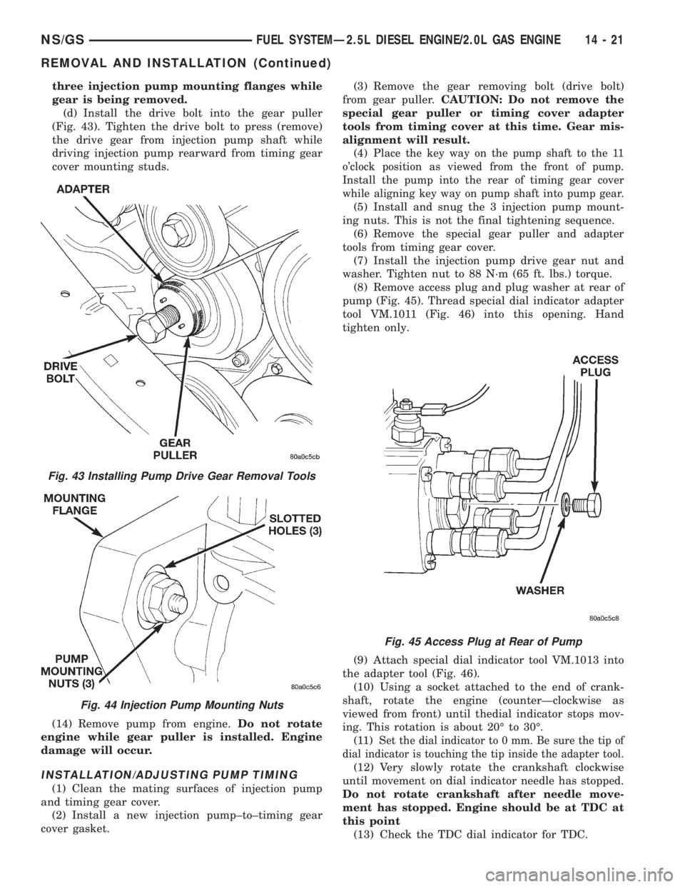
three injection pump mounting flanges while
gear is being removed.
(d) Install the drive bolt into the gear puller
(Fig. 43). Tighten the drive bolt to press (remove)
the drive gear from injection pump shaft while
driving injection pump rearward from timing gear
cover mounting studs.
(14) Remove pump from engine.Do not rotate
engine while gear puller is installed. Engine
damage will occur.
INSTALLATION/ADJUSTING PUMP TIMING
(1) Clean the mating surfaces of injection pump
and timing gear cover.
(2) Install a new injection pump±to±timing gear
cover gasket.(3) Remove the gear removing bolt (drive bolt)
from gear puller.CAUTION: Do not remove the
special gear puller or timing cover adapter
tools from timing cover at this time. Gear mis-
alignment will result.
(4) P
lace the key way on the pump shaft to the 11
o'clock position as viewed from the front of pump.
Install the pump into the rear of timing gear cover
while aligning key way on pump shaft into pump gear.
(5) Install and snug the 3 injection pump mount-
ing nuts. This is not the final tightening sequence.
(6) Remove the special gear puller and adapter
tools from timing gear cover.
(7) Install the injection pump drive gear nut and
washer. Tighten nut to 88 N´m (65 ft. lbs.) torque.
(8) Remove access plug and plug washer at rear of
pump (Fig. 45). Thread special dial indicator adapter
tool VM.1011 (Fig. 46) into this opening. Hand
tighten only.
(9) Attach special dial indicator tool VM.1013 into
the adapter tool (Fig. 46).
(10) Using a socket attached to the end of crank-
shaft, rotate the engine (counterÐclockwise as
viewed from front) until thedial indicator stops mov-
ing. This rotation is about 20É to 30É.
(11) S
et the dial indicator to 0 mm. Be sure the tip of
dial indicator is touching the tip inside the adapter tool.
(12) Very slowly rotate the crankshaft clockwise
until movement on dial indicator needle has stopped.
Do not rotate crankshaft after needle move-
ment has stopped. Engine should be at TDC at
this point
(13) Check the TDC dial indicator for TDC.
Fig. 43 Installing Pump Drive Gear Removal Tools
Fig. 44 Injection Pump Mounting Nuts
Fig. 45 Access Plug at Rear of Pump
NS/GSFUEL SYSTEMÐ2.5L DIESEL ENGINE/2.0L GAS ENGINE 14 - 21
REMOVAL AND INSTALLATION (Continued)
Page 1390 of 1938
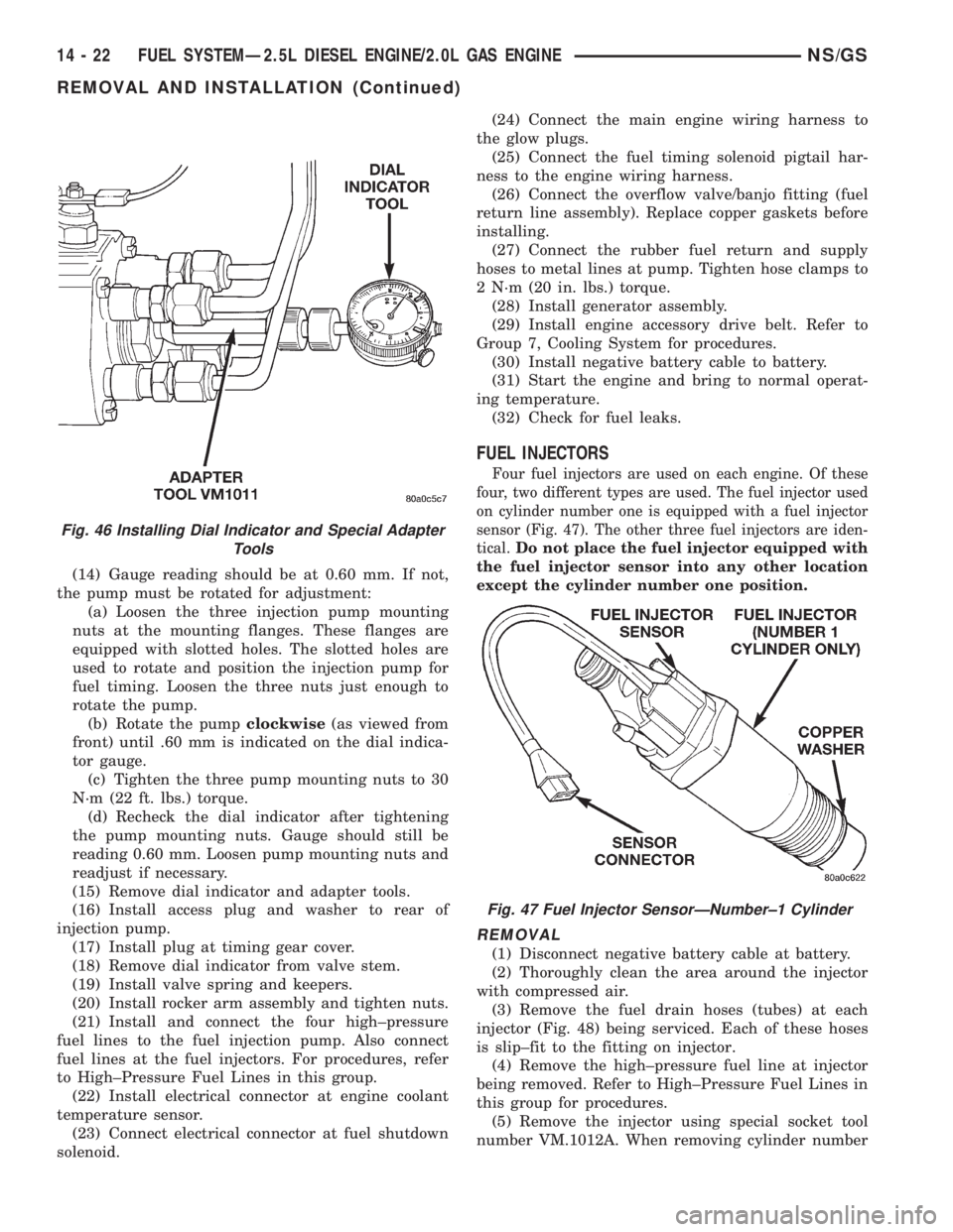
(14) Gauge reading should be at 0.60 mm. If not,
the pump must be rotated for adjustment:
(a) Loosen the three injection pump mounting
nuts at the mounting flanges. These flanges are
equipped with slotted holes. The slotted holes are
used to rotate and position the injection pump for
fuel timing. Loosen the three nuts just enough to
rotate the pump.
(b) Rotate the pumpclockwise(as viewed from
front) until .60 mm is indicated on the dial indica-
tor gauge.
(c) Tighten the three pump mounting nuts to 30
N´m (22 ft. lbs.) torque.
(d) Recheck the dial indicator after tightening
the pump mounting nuts. Gauge should still be
reading 0.60 mm. Loosen pump mounting nuts and
readjust if necessary.
(15) Remove dial indicator and adapter tools.
(16) Install access plug and washer to rear of
injection pump.
(17) Install plug at timing gear cover.
(18) Remove dial indicator from valve stem.
(19) Install valve spring and keepers.
(20) Install rocker arm assembly and tighten nuts.
(21) Install and connect the four high±pressure
fuel lines to the fuel injection pump. Also connect
fuel lines at the fuel injectors. For procedures, refer
to High±Pressure Fuel Lines in this group.
(22) Install electrical connector at engine coolant
temperature sensor.
(23) Connect electrical connector at fuel shutdown
solenoid.(24) Connect the main engine wiring harness to
the glow plugs.
(25) Connect the fuel timing solenoid pigtail har-
ness to the engine wiring harness.
(26) Connect the overflow valve/banjo fitting (fuel
return line assembly). Replace copper gaskets before
installing.
(27) Connect the rubber fuel return and supply
hoses to metal lines at pump. Tighten hose clamps to
2 N´m (20 in. lbs.) torque.
(28) Install generator assembly.
(29) Install engine accessory drive belt. Refer to
Group 7, Cooling System for procedures.
(30) Install negative battery cable to battery.
(31) Start the engine and bring to normal operat-
ing temperature.
(32) Check for fuel leaks.
FUEL INJECTORS
Four fuel injectors are used on each engine. Of these
four, two different types are used. The fuel injector used
on cylinder number one is equipped with a fuel injector
sensor (Fig. 47). The other three fuel injectors are iden-
tical.
Do not place the fuel injector equipped with
the fuel injector sensor into any other location
except the cylinder number one position.
REMOVAL
(1) Disconnect negative battery cable at battery.
(2) Thoroughly clean the area around the injector
with compressed air.
(3) Remove the fuel drain hoses (tubes) at each
injector (Fig. 48) being serviced. Each of these hoses
is slip±fit to the fitting on injector.
(4) Remove the high±pressure fuel line at injector
being removed. Refer to High±Pressure Fuel Lines in
this group for procedures.
(5) Remove the injector using special socket tool
number VM.1012A. When removing cylinder number
Fig. 46 Installing Dial Indicator and Special Adapter
Tools
Fig. 47 Fuel Injector SensorÐNumber±1 Cylinder
14 - 22 FUEL SYSTEMÐ2.5L DIESEL ENGINE/2.0L GAS ENGINENS/GS
REMOVAL AND INSTALLATION (Continued)
Page 1391 of 1938
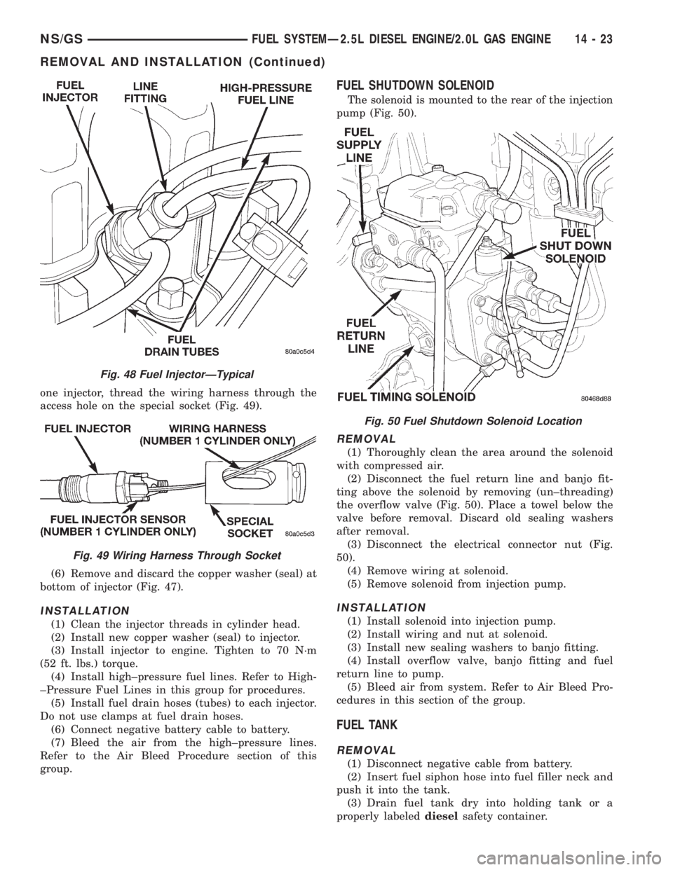
one injector, thread the wiring harness through the
access hole on the special socket (Fig. 49).
(6) Remove and discard the copper washer (seal) at
bottom of injector (Fig. 47).
INSTALLATION
(1) Clean the injector threads in cylinder head.
(2) Install new copper washer (seal) to injector.
(3) Install injector to engine. Tighten to 70 N´m
(52 ft. lbs.) torque.
(4) Install high±pressure fuel lines. Refer to High-
±Pressure Fuel Lines in this group for procedures.
(5) Install fuel drain hoses (tubes) to each injector.
Do not use clamps at fuel drain hoses.
(6) Connect negative battery cable to battery.
(7) Bleed the air from the high±pressure lines.
Refer to the Air Bleed Procedure section of this
group.
FUEL SHUTDOWN SOLENOID
The solenoid is mounted to the rear of the injection
pump (Fig. 50).
REMOVAL
(1) Thoroughly clean the area around the solenoid
with compressed air.
(2) Disconnect the fuel return line and banjo fit-
ting above the solenoid by removing (un±threading)
the overflow valve (Fig. 50). Place a towel below the
valve before removal. Discard old sealing washers
after removal.
(3) Disconnect the electrical connector nut (Fig.
50).
(4) Remove wiring at solenoid.
(5) Remove solenoid from injection pump.
INSTALLATION
(1) Install solenoid into injection pump.
(2) Install wiring and nut at solenoid.
(3) Install new sealing washers to banjo fitting.
(4) Install overflow valve, banjo fitting and fuel
return line to pump.
(5) Bleed air from system. Refer to Air Bleed Pro-
cedures in this section of the group.
FUEL TANK
REMOVAL
(1) Disconnect negative cable from battery.
(2) Insert fuel siphon hose into fuel filler neck and
push it into the tank.
(3) Drain fuel tank dry into holding tank or a
properly labeleddieselsafety container.
Fig. 48 Fuel InjectorÐTypical
Fig. 49 Wiring Harness Through Socket
Fig. 50 Fuel Shutdown Solenoid Location
NS/GSFUEL SYSTEMÐ2.5L DIESEL ENGINE/2.0L GAS ENGINE 14 - 23
REMOVAL AND INSTALLATION (Continued)
Page 1394 of 1938
HIGH-PRESSURE LINES
All high±pressure fuel lines are of the same length
and inside diameter. Correct high±pressure fuel line
usage and installation is critical to smooth engine
operation.
CAUTION: The high±pressure fuel lines must be
clamped securely in place in the holders. The lines
cannot contact each other or other components. Do
not attempt to weld high±pressure fuel lines or to
repair lines that are damaged. Only use the recom-
mended lines when replacement of high±pressure
fuel line is necessary.
REMOVAL
(1) Disconnect negative battery cable from battery.
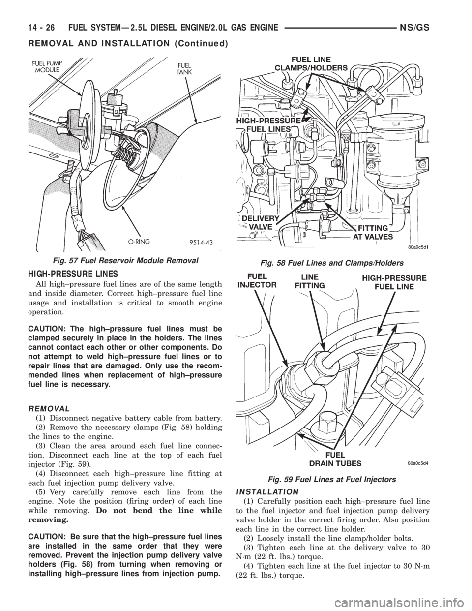
(2) Remove the necessary clamps (Fig. 58) holding
the lines to the engine.
(3) Clean the area around each fuel line connec-
tion. Disconnect each line at the top of each fuel
injector (Fig. 59).
(4) Disconnect each high±pressure line fitting at
each fuel injection pump delivery valve.
(5) Very carefully remove each line from the
engine. Note the position (firing order) of each line
while removing.Do not bend the line while
removing.
CAUTION: Be sure that the high±pressure fuel lines
are installed in the same order that they were
removed. Prevent the injection pump delivery valve
holders (Fig. 58) from turning when removing or
installing high±pressure lines from injection pump.
INSTALLATION
(1) Carefully position each high±pressure fuel line
to the fuel injector and fuel injection pump delivery
valve holder in the correct firing order. Also position
each line in the correct line holder.
(2) Loosely install the line clamp/holder bolts.
(3) Tighten each line at the delivery valve to 30
N´m (22 ft. lbs.) torque.
(4) Tighten each line at the fuel injector to 30 N´m
(22 ft. lbs.) torque.
Fig. 57 Fuel Reservoir Module RemovalFig. 58 Fuel Lines and Clamps/Holders
Fig. 59 Fuel Lines at Fuel Injectors
14 - 26 FUEL SYSTEMÐ2.5L DIESEL ENGINE/2.0L GAS ENGINENS/GS
REMOVAL AND INSTALLATION (Continued)
Page 1395 of 1938
Be sure the lines are not contacting each
other or any other component.
(5) Tighten the clamp bracket bolts to 24 N´m (18
ft. lbs.) torque.
(6) Bleed air from the fuel system. Refer to the Air
Bleed Procedure section of this group.
SPECIFICATIONS
FUEL TANK CAPACITY
75 Liters (20.0 Gals.)
Nominal refill capacities are shown. A variation
may be observed from vehicle to vehicle due to man-
ufacturing tolerances, ambient temperatures and
refill procedures.
IDLE SPEED
900 rpm625 rpmwith engine at normal operat-
ing temperature.
FUEL INJECTOR FIRING SEQUENCE
1±3±4±2
FUEL SYSTEM PRESSURE
Peak Injection Pressure/Fuel Injection Pump
Operating Pressure:40,000±45,000 kPa (5801±
6526 psi).
Opening Pressure of Fuel Injector:
15,000±15,800 kPa (2175±2291 psi).
NS/GSFUEL SYSTEMÐ2.5L DIESEL ENGINE/2.0L GAS ENGINE 14 - 27
REMOVAL AND INSTALLATION (Continued)