1996 CHRYSLER VOYAGER air condition
[x] Cancel search: air conditionPage 1885 of 1938
SYSTEM LEAK CHECKING
WARNING: R-134a SERVICE EQUIPMENT OR VEHI-
CLE A/C SYSTEM SHOULD NOT BE PRESSURE
TESTED OR LEAK TESTED WITH COMPRESSED
AIR. SOME MIXTURES OF AIR/R-134a HAVE BEEN
SHOWN TO BE COMBUSTIBLE AT ELEVATED
PRESSURES. THESE MIXTURES ARE POTENTIALLY
DANGEROUS AND MAY RESULT IN FIRE OR
EXPLOSION CAUSING INJURY OR PROPERTY
DAMAGE.
If the A/C system is not cooling properly, determine
if the refrigerant system is fully charged with
R-134a. This is accomplished by performing a system
Charge Level-Check or Fill. If while performing this
test A/C liquid line pressure is less than 207 kPa (30
psi) proceed to Empty Refrigerant System Leak Test.
If liquid line pressure is greater than 207 kPa (30
psi) proceed to low refrigerant level leak test. If the
refrigerant system is empty or low in refrigerant
charge, a leak at any line fitting or component seal is
likely. A review of the fittings, lines and components
for oily residue is an indication of the leak location.
To detect a leak in the refrigerant system, perform
one of the following procedures as indicated by the
symptoms.
WARNING: AVOID BREATHING A/C REFRIGERANT
AND LUBRICANT VAPOR OR MIST. EXPOSURE MAY
IRRITATE EYES, NOSE AND THROAT. USE ONLY
APPROVED SERVICE EQUIPMENT MEETING SAE
REQUIREMENTS TO DISCHARGE R-134a SYSTEM.
IF ACCIDENTAL SYSTEM DISCHARGE OCCURS,
VENTILATE WORK AREA BEFORE RESUMING SER-
VICE.
EMPTY REFRIGERANT SYSTEM LEAK TEST
(1) Evacuate the refrigerant system to the lowest
degree of vacuum possible (about 28 in Hg.). Deter-
mine if the system holds a vacuum for 15 minutes. If
vacuum is held, a leak is probably not present. If sys-
tem will not maintain vacuum level, proceed with
this procedure.
(2) Prepare a .284 Kg. (10 oz.) refrigerant charge
to be injected into the system.
(3) Connect and dispense .284 Kg. (10 oz.) of
refrigerant into the evacuated refrigerant system.
(4) Proceed to step two of Low Refrigerant Level
Leak Test.
LOW REFRIGERANT LEVEL LEAK TEST
(1) Determine if there is any (R-134a) refrigerant
in the system. Use the scan tool (DRB) under the
menu Systems Sensors±A/C Pressure test or pressuregauge liquid line temperature partial charge check.
See system charge level check or fill for procedure.
(2) Position the vehicle in a wind free work area.
This will aid in detecting small leaks.
(3) Bring the refrigerant system up to operating
temperature and pressure. This is done by allowing
the engine to run for five minutes with the system
set to the following:
²Transaxle in Park
²Engine Idling at 700 rpm
²A/C Controls Set in 100 percent outside air
²Full Panel Mode
²Blower motor ON HIGH
²A/C in the ON position
²Front Windows Open.
²Rear Air Off (If Equipped)
CAUTION: A leak detector designed for R-12 refrig-
erant will not detect leaks in a R-134a refrigerant
system.
(4) Shut off the vehicle and wait 2 to 7 minutes.
Then use an Electronic Leak Detector that is
designed to detect R-134a type refrigerant and search
for leaks. Fittings, lines, or components that appear
to be oily usually indicates a refrigerant leak. To
inspect the evaporator core for leaks, insert the leak
detector probe into the recirculating air door opening
or a heat duct.
If a thorough leak check has been completed with-
out indication of a leak, proceed to System Charge
Level-Check or Fill.
REMOVAL AND INSTALLATION
A/C PRESSURE TRANSDUCER
REMOVAL
(1) Disconnect the wire connector at the pressure
transducer.
(2) Using an open end wrench, remove the trans-
ducer from the liquid line (Fig. 11).
INSTALLATION
(1) Replace transducer O-ring.
(2) For installation, reverse the above procedures.
A/C SERVICE PORTS
WARNING: THE REFRIGERATION SYSTEM MUST
BE COMPLETELY EMPTY BEFORE PROCEEDING
WITH THIS OPERATION.
The High Side service port is serviceable, the Low
Side is not serviceable.
NS/GSHEATING AND AIR CONDITIONING 24 - 19
SERVICE PROCEDURES (Continued)
Page 1886 of 1938
REMOVAL
(1) Disconnect the battery negative cable.
(2) Recover A/C system refrigerant.
(3) Unscrew the High Side service port from the
liquid line.
(4) Remove O-ring
INSTALLATION
For installation, reverse the above procedures.
²Install new O-ring.
²Evacuate and recharge A/C system.
BLEND-AIR DOOR ACTUATOR
REMOVAL
The air conditioning system can be equipped with
either a standard, single blend-air door actuator, or it
can be equipped with dual actuators. The dual sys-
tem has separate blend-air controls. This allows for
separate control of the driver's side air, and the pas-
senger side air (Fig. 12).(1) Remove the lower left side steering column
cover. Refer to Group 8E, Instrument Panel and Sys-
tems.
(2) Remove ABS control module (Fig. 13).
(3) Remove blend-air actuator connector.
(4) Remove blend-air actuator (Fig. 14).
INSTALLATION
(1) For installation, reverse the above procedures.
(2) Perform the HVAC Control Calibration Diag-
nostic and Cooldown test. Repeating the test is nec-
essary to clear the fault codes.
BLOWER MOTOR AND WHEEL ASSEMBLY
REMOVAL
(1) Remove glove box. Refer to Group 8E, Instru-
ment Panel and Systems.
(2) Remove (4) hex head screws to blower motor
cover (Fig. 15).
(3) Disconnect blower motor wiring.
Fig. 11 A/C Pressure Transducer Removal
Fig. 12 Side View Of HVAC With Actuators
Fig. 13 ABS Control Module
Fig. 14 Blend-Air Actuator
24 - 20 HEATING AND AIR CONDITIONINGNS/GS
REMOVAL AND INSTALLATION (Continued)
Page 1887 of 1938
(4) Remove grommet for wiring (Fig. 16). Feed wir-
ing through blower housing (Fig. 17).
(5) Remove mounting screws for blower motor (Fig.
18).(6) Allow the blower assembly to drop down, and
remove assembly from vehicle.
INSTALLATION
For installation, reverse the above procedures.
BLOWER MOTOR RESISTOR BLOCK
REMOVAL
(1) Open hood.
(2) Locate and remove the wire connector from the
blower resistor block. Block is located at the back of
the engine compartment on the passenger side of the
vehicle under the wiper module (Fig. 19).
NOTE: It is not necessary to remove the wiper
module to access the resistor block.
WARNING: THE RESISTOR BLOCK MAY BE HOT.
DO NOT ATTEMPT TO SERVICE THE RESISTOR
BLOCK IF THE SYSTEM HAS BEEN RUNNING
RECENTLY. LET THE SYSTEM COOL DOWN
BEFORE REPAIRS ARE INITIATED.
Fig. 15 Blower Motor Cover
Fig. 16 Wiring Grommet
Fig. 17 Feeding Wiring Through Housing
Fig. 18 Blower Motor Screws
Fig. 19 Resistor Block Removal
NS/GSHEATING AND AIR CONDITIONING 24 - 21
REMOVAL AND INSTALLATION (Continued)
Page 1888 of 1938
(3) Remove resistor block by inserting a flat blade
pry tool on the side of the resistor block and pushing
inward. Two guide lines are shown on the right hand
edge of the resistor block to help guide the blade
position. This will release the clips on the side of the
resistor block. Pull resistor block out.
INSTALLATION
For installation, reverse the above procedures.
Make sure the ªTOPº lettering is on the top of the
resistor. The coils on the Resistor Block should not be
contacting one another. Before installation, gently
separate the coils (with fingers only) if one coil is
contacting another.
BLOWER MOTOR WHEEL
The blower motor wheel is not serviced separately.
If the wheel needs to be replaced it is serviced as an
assembly of the blower motor. For service procedure
information, refer to Blower Motor Replacement in
this group.
COMPRESSOR (2.5L TURBO DIESEL)
REMOVAL
WARNING: REFER TO REFRIGERANT SERVICE
PROCEDURES FOR INFORMATION REGARDING
PROPER RECOVERY OF THE REFRIGERANT
BEFORE ATTEMPTING TO REMOVE THE COM-
PRESSOR.(1) Disconnect negative battery cable.
(2) Reclaim refrigerant.
(3) Raise vehicle on hoist.
(4) Remove refrigerant lines from compressor and
cap all lines (Fig. 10).
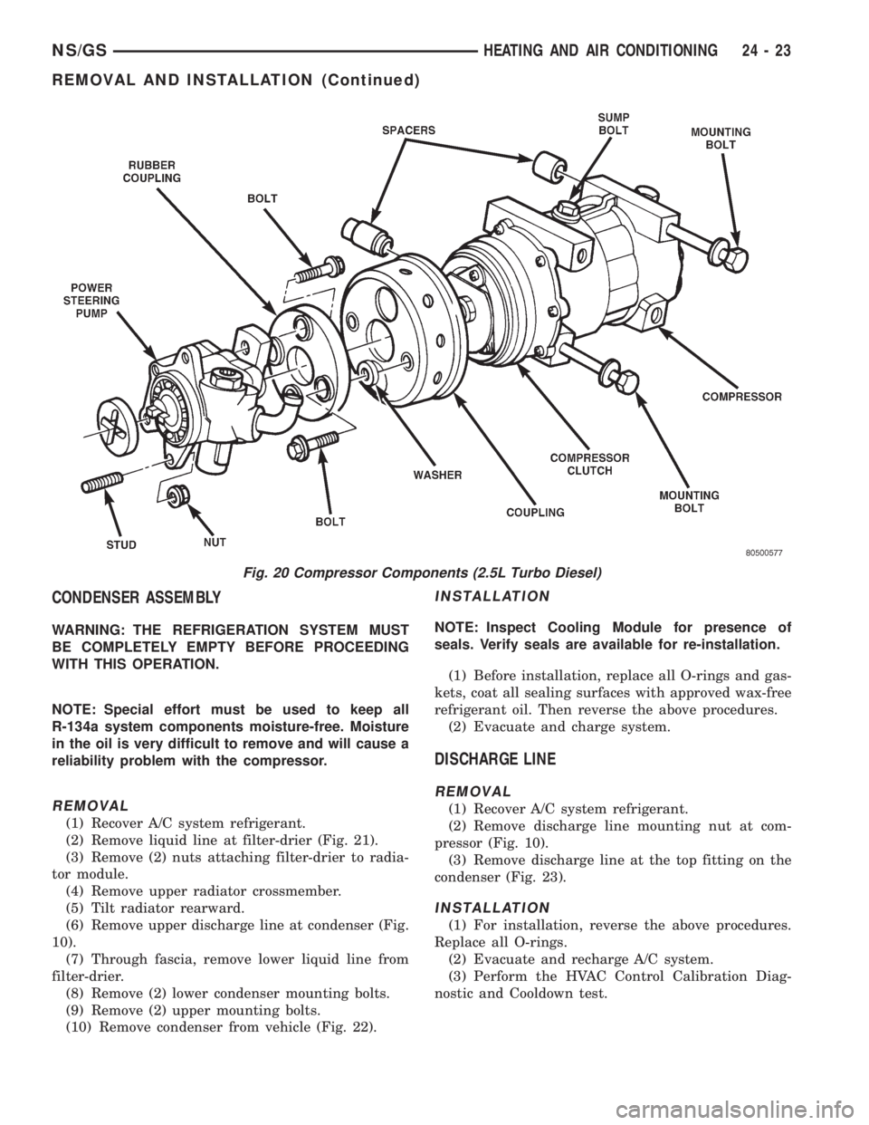
(5) Remove flex drive bolts from behind the power
steering pump (Fig. 20).
(6) Remove compressor mounting bolts (Fig. 20).
(7) pry compressor off of the dowel pins and
remove compressor.
INSTALLATION
(1) Transfer mounting spacer/bushings onto the
new compressor.
(2) Lift compressor into place and start compressor
mounting bolts. Do not tighten bolts at this time. The
compressor may have to be moved slightly to align
the flex drive bolts.
(3) Align compressor clutch with flex drive. Then
start both flex drive bolts. Tighten the bolts after
both flex drive bolts have been installed.
(4) Tighten compressor mounting bolts.
(5) Lower vehicle and install refrigerant lines.
Always replace O-rings and gaskets.
(6) Evacuate refrigerant system. Charge system
with the correct amount of R-134a refrigerant. The
refrigerant capacity is .91 kg.67 gm. (32 oz.62.0
oz.).
24 - 22 HEATING AND AIR CONDITIONINGNS/GS
REMOVAL AND INSTALLATION (Continued)
Page 1889 of 1938
CONDENSER ASSEMBLY
WARNING: THE REFRIGERATION SYSTEM MUST
BE COMPLETELY EMPTY BEFORE PROCEEDING
WITH THIS OPERATION.
NOTE: Special effort must be used to keep all
R-134a system components moisture-free. Moisture
in the oil is very difficult to remove and will cause a
reliability problem with the compressor.
REMOVAL
(1) Recover A/C system refrigerant.
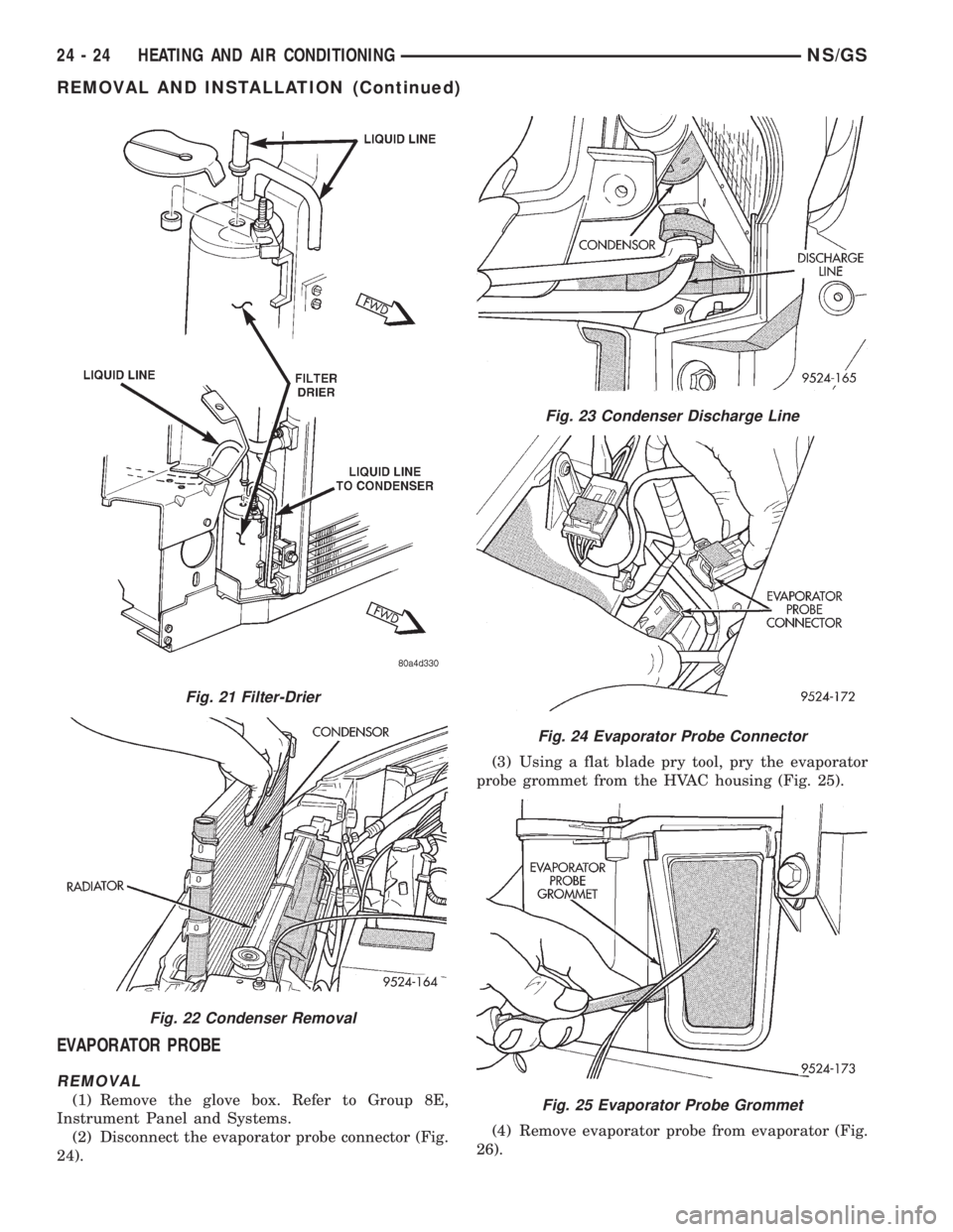
(2) Remove liquid line at filter-drier (Fig. 21).
(3) Remove (2) nuts attaching filter-drier to radia-
tor module.
(4) Remove upper radiator crossmember.
(5) Tilt radiator rearward.
(6) Remove upper discharge line at condenser (Fig.
10).
(7) Through fascia, remove lower liquid line from
filter-drier.
(8) Remove (2) lower condenser mounting bolts.
(9) Remove (2) upper mounting bolts.
(10) Remove condenser from vehicle (Fig. 22).
INSTALLATION
NOTE: Inspect Cooling Module for presence of
seals. Verify seals are available for re-installation.
(1) Before installation, replace all O-rings and gas-
kets, coat all sealing surfaces with approved wax-free
refrigerant oil. Then reverse the above procedures.
(2) Evacuate and charge system.
DISCHARGE LINE
REMOVAL
(1) Recover A/C system refrigerant.
(2) Remove discharge line mounting nut at com-
pressor (Fig. 10).
(3) Remove discharge line at the top fitting on the
condenser (Fig. 23).
INSTALLATION
(1) For installation, reverse the above procedures.
Replace all O-rings.
(2) Evacuate and recharge A/C system.
(3) Perform the HVAC Control Calibration Diag-
nostic and Cooldown test.
Fig. 20 Compressor Components (2.5L Turbo Diesel)
NS/GSHEATING AND AIR CONDITIONING 24 - 23
REMOVAL AND INSTALLATION (Continued)
Page 1890 of 1938
EVAPORATOR PROBE
REMOVAL
(1) Remove the glove box. Refer to Group 8E,
Instrument Panel and Systems.
(2) Disconnect the evaporator probe connector (Fig.
24).(3) Using a flat blade pry tool, pry the evaporator
probe grommet from the HVAC housing (Fig. 25).
(4) Remove evaporator probe from evaporator (Fig.
26).
Fig. 21 Filter-Drier
Fig. 22 Condenser Removal
Fig. 23 Condenser Discharge Line
Fig. 24 Evaporator Probe Connector
Fig. 25 Evaporator Probe Grommet
24 - 24 HEATING AND AIR CONDITIONINGNS/GS
REMOVAL AND INSTALLATION (Continued)
Page 1891 of 1938
INSTALLATION
For installation, reverse the above procedures.
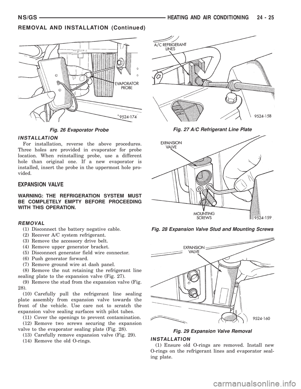
Three holes are provided in evaporator for probe
location. When reinstalling probe, use a different
hole than original one. If a new evaporator is
installed, insert the probe in the uppermost hole pro-
vided.
EXPANSION VALVE
WARNING: THE REFRIGERATION SYSTEM MUST
BE COMPLETELY EMPTY BEFORE PROCEEDING
WITH THIS OPERATION.
REMOVAL
(1) Disconnect the battery negative cable.
(2) Recover A/C system refrigerant.
(3) Remove the accessory drive belt.
(4) Remove upper generator bracket.
(5) Disconnect generator field wire connector.
(6) Push generator forward.
(7) Remove ground wire at dash panel.
(8) Remove the nut retaining the refrigerant line
sealing plate to the expansion valve (Fig. 27).
(9) Remove the stud from the expansion valve (Fig.
28).
(10) Carefully pull the refrigerant line sealing
plate assembly from expansion valve towards the
front of the vehicle. Use care not to scratch the
expansion valve sealing surfaces with pilot tubes.
(11) Cover the openings to prevent contamination.
(12) Remove two screws securing the expansion
valve to the evaporator sealing plate (Fig. 28).
(13) Carefully remove expansion valve (Fig. 29).
(14) Remove the old O-rings.
INSTALLATION
(1) Ensure old O-rings are removed. Install new
O-rings on the refrigerant lines and evaporator seal-
ing plate.
Fig. 26 Evaporator ProbeFig. 27 A/C Refrigerant Line Plate
Fig. 28 Expansion Valve Stud and Mounting Screws
Fig. 29 Expansion Valve Removal
NS/GSHEATING AND AIR CONDITIONING 24 - 25
REMOVAL AND INSTALLATION (Continued)
Page 1892 of 1938
(2) Hand-start the stud into the expansion valve
and torque to7-11N´m(64-96in.lbs.).
(3) Carefully install the expansion valve to the
sealing plate. Install the two screws and tighten 8 to
14 N´m (70 to 130 in. lbs.) torque.
(4) Carefully install the refrigerant lines and seal-
ing plate to the expansion valve. Install the nut and
tighten 20 to 26 N´m (170 to 230 in. lbs.) torque.
(5) Install the ground wire at dash panel.
(6) Pull generator back into the proper position for
bracket mounting.
(7) Install generator field wire connector.
(8) Install the upper generator bracket.
(9) Install accessory drive belt.
(10) Evacuate and recharge system.
(11) After expansion valve is installed, the system
is charged, and leaks have checked repeat the A/C
performance check.
FILTER-DRIER ASSEMBLY
REMOVAL
WARNING: THE REFRIGERATION SYSTEM MUST
BE COMPLETELY EMPTY BEFORE PROCEEDING
WITH THIS OPERATION.
(1) Recover A/C system refrigerant.
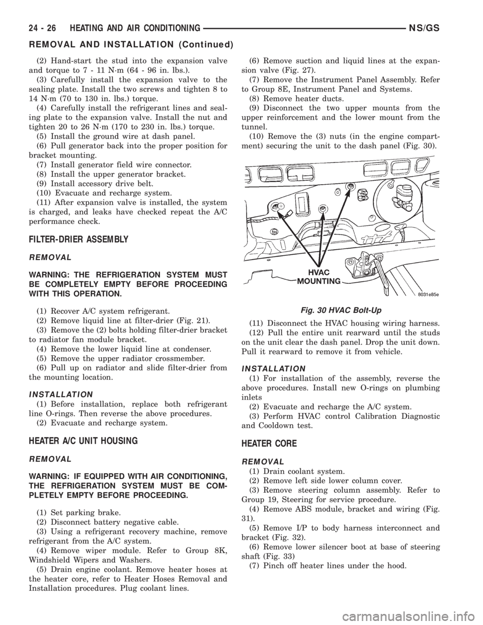
(2) Remove liquid line at filter-drier (Fig. 21).
(3) Remove the (2) bolts holding filter-drier bracket
to radiator fan module bracket.
(4) Remove the lower liquid line at condenser.
(5) Remove the upper radiator crossmember.
(6) Pull up on radiator and slide filter-drier from
the mounting location.
INSTALLATION
(1) Before installation, replace both refrigerant
line O-rings. Then reverse the above procedures.
(2) Evacuate and recharge system.
HEATER A/C UNIT HOUSING
REMOVAL
WARNING: IF EQUIPPED WITH AIR CONDITIONING,
THE REFRIGERATION SYSTEM MUST BE COM-
PLETELY EMPTY BEFORE PROCEEDING.
(1) Set parking brake.
(2) Disconnect battery negative cable.
(3) Using a refrigerant recovery machine, remove
refrigerant from the A/C system.
(4) Remove wiper module. Refer to Group 8K,
Windshield Wipers and Washers.
(5) Drain engine coolant. Remove heater hoses at
the heater core, refer to Heater Hoses Removal and
Installation procedures. Plug coolant lines.(6) Remove suction and liquid lines at the expan-
sion valve (Fig. 27).
(7) Remove the Instrument Panel Assembly. Refer
to Group 8E, Instrument Panel and Systems.
(8) Remove heater ducts.
(9) Disconnect the two upper mounts from the
upper reinforcement and the lower mount from the
tunnel.
(10) Remove the (3) nuts (in the engine compart-
ment) securing the unit to the dash panel (Fig. 30).
(11) Disconnect the HVAC housing wiring harness.
(12) Pull the entire unit rearward until the studs
on the unit clear the dash panel. Drop the unit down.
Pull it rearward to remove it from vehicle.
INSTALLATION
(1) For installation of the assembly, reverse the
above procedures. Install new O-rings on plumbing
inlets
(2) Evacuate and recharge the A/C system.
(3) Perform HVAC control Calibration Diagnostic
and Cooldown test.
HEATER CORE
REMOVAL
(1) Drain coolant system.
(2) Remove left side lower column cover.
(3) Remove steering column assembly. Refer to
Group 19, Steering for service procedure.
(4) Remove ABS module, bracket and wiring (Fig.
31).
(5) Remove I/P to body harness interconnect and
bracket (Fig. 32).
(6) Remove lower silencer boot at base of steering
shaft (Fig. 33)
(7) Pinch off heater lines under the hood.
Fig. 30 HVAC Bolt-Up
24 - 26 HEATING AND AIR CONDITIONINGNS/GS
REMOVAL AND INSTALLATION (Continued)