1996 CHRYSLER VOYAGER engine oil
[x] Cancel search: engine oilPage 1198 of 1938
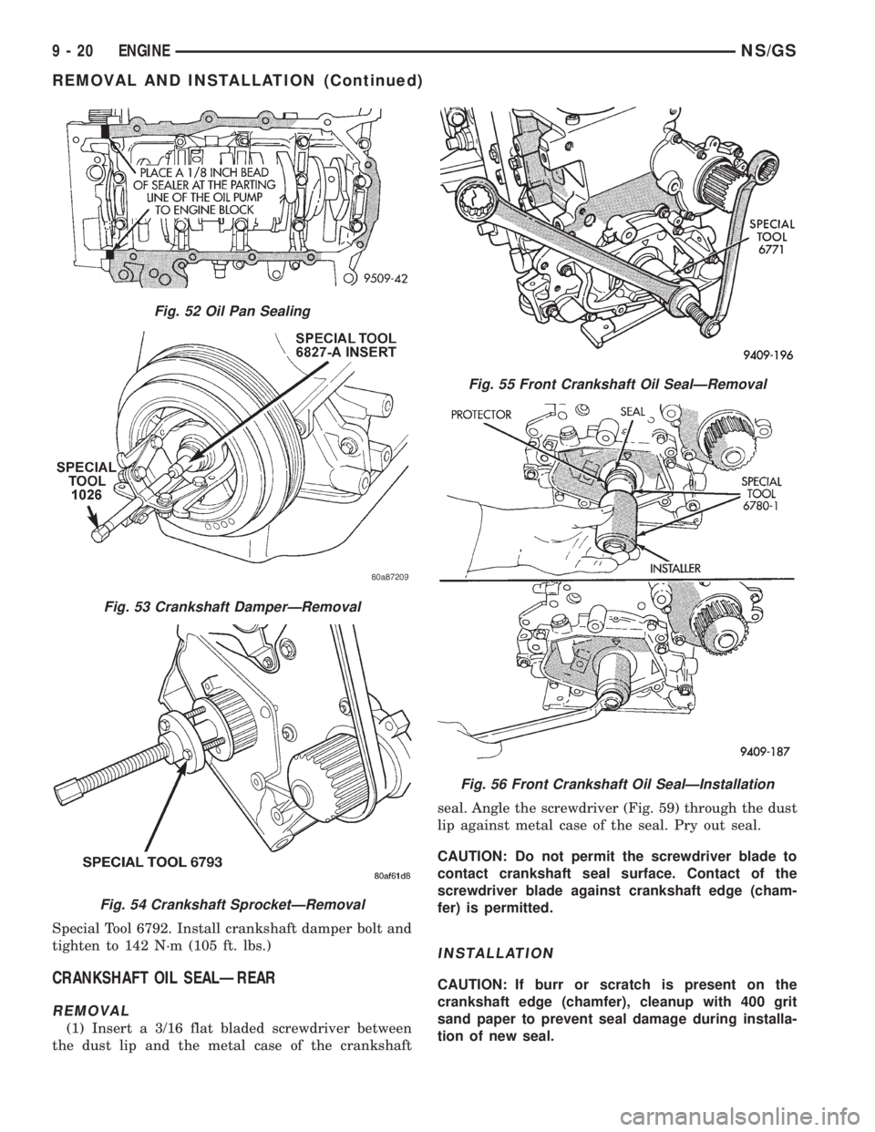
Special Tool 6792. Install crankshaft damper bolt and
tighten to 142 N´m (105 ft. lbs.)
CRANKSHAFT OIL SEALÐREAR
REMOVAL
(1) Insert a 3/16 flat bladed screwdriver between
the dust lip and the metal case of the crankshaftseal. Angle the screwdriver (Fig. 59) through the dust
lip against metal case of the seal. Pry out seal.
CAUTION: Do not permit the screwdriver blade to
contact crankshaft seal surface. Contact of the
screwdriver blade against crankshaft edge (cham-
fer) is permitted.
INSTALLATION
CAUTION: If burr or scratch is present on the
crankshaft edge (chamfer), cleanup with 400 grit
sand paper to prevent seal damage during installa-
tion of new seal.
Fig. 52 Oil Pan Sealing
Fig. 53 Crankshaft DamperÐRemoval
Fig. 54 Crankshaft SprocketÐRemoval
Fig. 55 Front Crankshaft Oil SealÐRemoval
Fig. 56 Front Crankshaft Oil SealÐInstallation
9 - 20 ENGINENS/GS
REMOVAL AND INSTALLATION (Continued)
Page 1199 of 1938
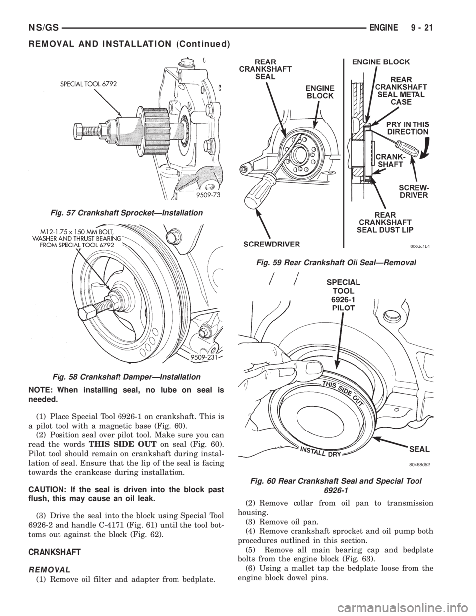
NOTE: When installing seal, no lube on seal is
needed.
(1) Place Special Tool 6926-1 on crankshaft. This is
a pilot tool with a magnetic base (Fig. 60).
(2) Position seal over pilot tool. Make sure you can
read the wordsTHIS SIDE OUTon seal (Fig. 60).
Pilot tool should remain on crankshaft during instal-
lation of seal. Ensure that the lip of the seal is facing
towards the crankcase during installation.
CAUTION: If the seal is driven into the block past
flush, this may cause an oil leak.
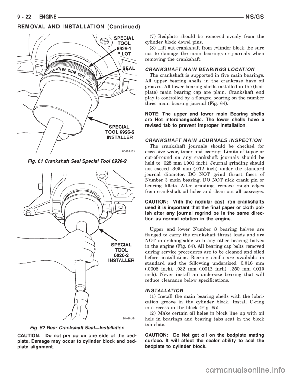
(3) Drive the seal into the block using Special Tool
6926-2 and handle C-4171 (Fig. 61) until the tool bot-
toms out against the block (Fig. 62).
CRANKSHAFT
REMOVAL
(1) Remove oil filter and adapter from bedplate.(2) Remove collar from oil pan to transmission
housing.
(3) Remove oil pan.
(4) Remove crankshaft sprocket and oil pump both
procedures outlined in this section.
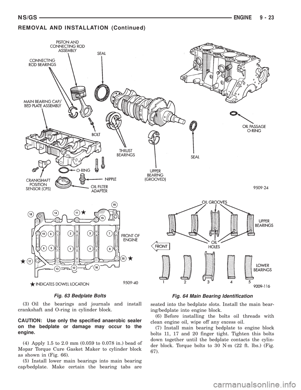
(5) Remove all main bearing cap and bedplate
bolts from the engine block (Fig. 63).
(6) Using a mallet tap the bedplate loose from the
engine block dowel pins.
Fig. 57 Crankshaft SprocketÐInstallation
Fig. 58 Crankshaft DamperÐInstallation
Fig. 59 Rear Crankshaft Oil SealÐRemoval
Fig. 60 Rear Crankshaft Seal and Special Tool
6926-1
NS/GSENGINE 9 - 21
REMOVAL AND INSTALLATION (Continued)
Page 1200 of 1938
CAUTION: Do not pry up on one side of the bed-
plate. Damage may occur to cylinder block and bed-
plate alignment.(7) Bedplate should be removed evenly from the
cylinder block dowel pins.
(8) Lift out crankshaft from cylinder block. Be sure
not to damage the main bearings or journals when
removing the crankshaft.
CRANKSHAFT MAIN BEARINGS LOCATION
The crankshaft is supported in five main bearings.
All upper bearing shells in the crankcase have oil
grooves. All lower bearing shells installed in the (bed-
plate) main bearing cap are plain. Crankshaft end
play is controlled by a flanged bearing on the number
three main bearing journal (Fig. 64).
NOTE: The upper and lower main Bearing shells
are Not interchangeable. The lower shells have a
revised tab to prevent improper installation.
CRANKSHAFT MAIN JOURNALS INSPECTION
The crankshaft journals should be checked for
excessive wear, taper and scoring. Limits of taper or
out-of-round on any crankshaft journals should be
held to .025 mm (.001 inch). Journal grinding should
not exceed .305 mm (.012 inch) under the standard
journal diameter. DO NOT grind thrust faces of
Number 3 main bearing. DO NOT nick crank pin or
bearing fillets. After grinding, remove rough edges
from crankshaft oil holes and clean out all passages.
CAUTION: With the nodular cast iron crankshafts
used it is important that the final paper or cloth pol-
ish after any journal regrind be in the same direc-
tion as normal rotation in the engine.
Upper and lower Number 3 bearing halves are
flanged to carry the crankshaft thrust loads and are
NOT interchangeable with any other bearing halves
in the engine (Fig. 64). All bearing cap bolts removed
during service procedures are to be cleaned and oiled
before installation. Bearing shells are available in
standard and the following undersized: 0.016 mm
(.0006 inch), .032 mm (.0012 inch), .250 mm (.010
inch). Never install an undersize bearing that will
reduce clearance below specifications.
INSTALLATION
(1) Install the main bearing shells with the lubri-
cation groove in the cylinder block. Install O-ring
into recess in the block (Fig. 65).
(2) Make certain oil holes in block line up with oil
hole in bearings and bearing tabs seat in the block
tab slots.
CAUTION: Do Not get oil on the bedplate mating
surface. It will affect the sealer ability to seal the
bedplate to cylinder block.
Fig. 61 Crankshaft Seal Special Tool 6926-2
Fig. 62 Rear Crankshaft SealÐInstallation
9 - 22 ENGINENS/GS
REMOVAL AND INSTALLATION (Continued)
Page 1201 of 1938
(3) Oil the bearings and journals and install
crankshaft and O-ring in cylinder block.
CAUTION: Use only the specified anaerobic sealer
on the bedplate or damage may occur to the
engine.
(4) Apply 1.5 to 2.0 mm (0.059 to 0.078 in.) bead of
Mopar Torque Cure Gasket Maker to cylinder block
as shown in (Fig. 66).
(5) Install lower main bearings into main bearing
cap/bedplate. Make certain the bearing tabs areseated into the bedplate slots. Install the main bear-
ing/bedplate into engine block.
(6) Before installing the bolts oil threads with
clean engine oil, wipe off any excess oil.
(7) Install main bearing bedplate to engine block
bolts 11, 17 and 20 finger tight. Tighten this bolts
down together until the bedplate contacts the cylin-
der block. Torque bolts to 30 N´m (22 ft. lbs.) (Fig.
67).
Fig. 63 Bedplate BoltsFig. 64 Main Bearing Identification
NS/GSENGINE 9 - 23
REMOVAL AND INSTALLATION (Continued)
Page 1202 of 1938
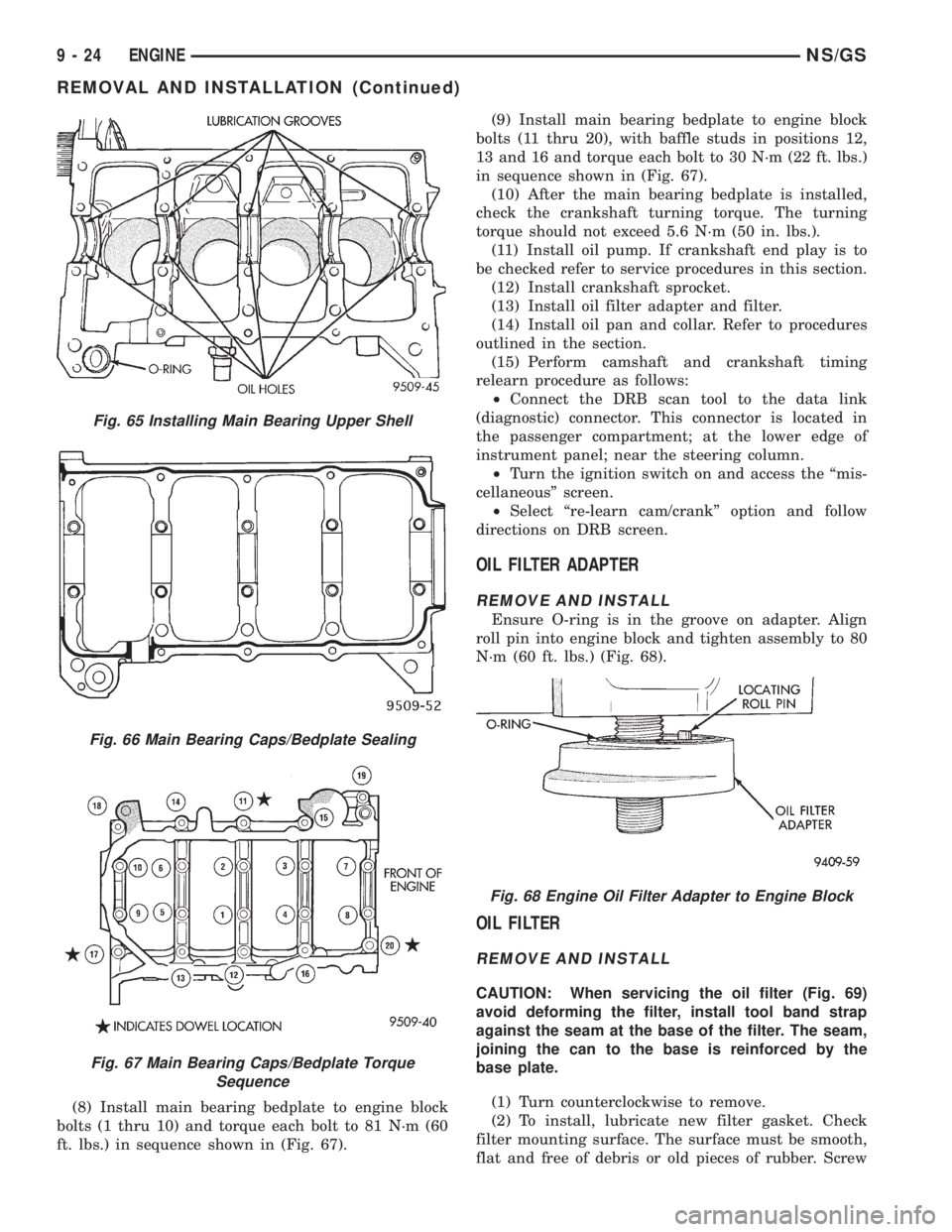
(8) Install main bearing bedplate to engine block
bolts (1 thru 10) and torque each bolt to 81 N´m (60
ft. lbs.) in sequence shown in (Fig. 67).(9) Install main bearing bedplate to engine block
bolts (11 thru 20), with baffle studs in positions 12,
13 and 16 and torque each bolt to 30 N´m (22 ft. lbs.)
in sequence shown in (Fig. 67).
(10) After the main bearing bedplate is installed,
check the crankshaft turning torque. The turning
torque should not exceed 5.6 N´m (50 in. lbs.).
(11) Install oil pump. If crankshaft end play is to
be checked refer to service procedures in this section.
(12) Install crankshaft sprocket.
(13) Install oil filter adapter and filter.
(14) Install oil pan and collar. Refer to procedures
outlined in the section.
(15) Perform camshaft and crankshaft timing
relearn procedure as follows:
²Connect the DRB scan tool to the data link
(diagnostic) connector. This connector is located in
the passenger compartment; at the lower edge of
instrument panel; near the steering column.
²Turn the ignition switch on and access the ªmis-
cellaneousº screen.
²Select ªre-learn cam/crankº option and follow
directions on DRB screen.
OIL FILTER ADAPTER
REMOVE AND INSTALL
Ensure O-ring is in the groove on adapter. Align
roll pin into engine block and tighten assembly to 80
N´m (60 ft. lbs.) (Fig. 68).
OIL FILTER
REMOVE AND INSTALL
CAUTION: When servicing the oil filter (Fig. 69)
avoid deforming the filter, install tool band strap
against the seam at the base of the filter. The seam,
joining the can to the base is reinforced by the
base plate.
(1) Turn counterclockwise to remove.
(2) To install, lubricate new filter gasket. Check
filter mounting surface. The surface must be smooth,
flat and free of debris or old pieces of rubber. Screw
Fig. 65 Installing Main Bearing Upper Shell
Fig. 66 Main Bearing Caps/Bedplate Sealing
Fig. 67 Main Bearing Caps/Bedplate Torque
Sequence
Fig. 68 Engine Oil Filter Adapter to Engine Block
9 - 24 ENGINENS/GS
REMOVAL AND INSTALLATION (Continued)
Page 1203 of 1938
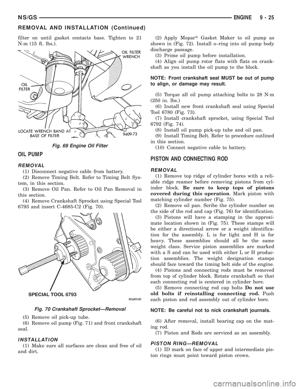
filter on until gasket contacts base. Tighten to 21
N´m (15 ft. lbs.).
OIL PUMP
REMOVAL
(1) Disconnect negative cable from battery.
(2) Remove Timing Belt. Refer to Timing Belt Sys-
tem, in this section.
(3) Remove Oil Pan. Refer to Oil Pan Removal in
this section.
(4) Remove Crankshaft Sprocket using Special Tool
6793 and insert C-4685-C2 (Fig. 70).
(5) Remove oil pick-up tube.
(6) Remove oil pump (Fig. 71) and front crankshaft
seal.
INSTALLATION
(1) Make sure all surfaces are clean and free of oil
and dirt.(2) Apply MopartGasket Maker to oil pump as
shown in (Fig. 72). Install o±ring into oil pump body
discharge passage.
(3) Prime oil pump before installation.
(4) Align oil pump rotor flats with flats on crank-
shaft as you install the oil pump to the block.
NOTE: Front crankshaft seal MUST be out of pump
to align, or damage may result.
(5) Torque all oil pump attaching bolts to 28 N´m
(250 in. lbs.)
(6) Install new front crankshaft seal using Special
Tool 6780 (Fig. 73).
(7) Install crankshaft sprocket, using Special Tool
6792 (Fig. 74).
(8) Install oil pump pick-up tube and oil pan.
(9) Install Timing Belt. Refer to procedure outlined
in this section.
(10) Connect negative cable to battery.
PISTON AND CONNECTING ROD
REMOVAL
(1) Remove top ridge of cylinder bores with a reli-
able ridge reamer before removing pistons from cyl-
inder block.Be sure to keep tops of pistons
covered during this operation. Mark piston with
matching cylinder number (Fig. 75).
(2) Remove oil pan. Scribe the cylinder number on
the side of the rod and cap (Fig. 76) for identification.
(3) Pistons will have a stamping in the approxi-
mate location shown in (Fig. 75). These stamps will
be either a directional arrow or a weight identifica-
tion for the assembly. L is for light and H is for
heavy. These assemblies should all be the same
weight class. Service piston assemblies are marked
with a S and can be used with either L or H produc-
tion assemblies. The weight designation stamps
should face toward the timing belt side of the engine.
(4) Pistons and connecting rods must be removed
from top of cylinder block. Rotate crankshaft so that
each connecting rod is centered in cylinder bore.
(5) Remove connecting rod cap boltsDo not use
old bolts if reinstalling connecting rod.Push
each piston and rod assembly out of cylinder bore.
NOTE: Be careful not to nick crankshaft journals.
(6) After removal, install bearing cap on the mat-
ing rod.
(7) Piston and Rods are serviced as an assembly.
PISTON RINGÐREMOVAL
(1) ID mark on face of upper and intermediate pis-
ton rings must point toward piston crown.
Fig. 69 Engine Oil Filter
Fig. 70 Crankshaft SprocketÐRemoval
NS/GSENGINE 9 - 25
REMOVAL AND INSTALLATION (Continued)
Page 1204 of 1938
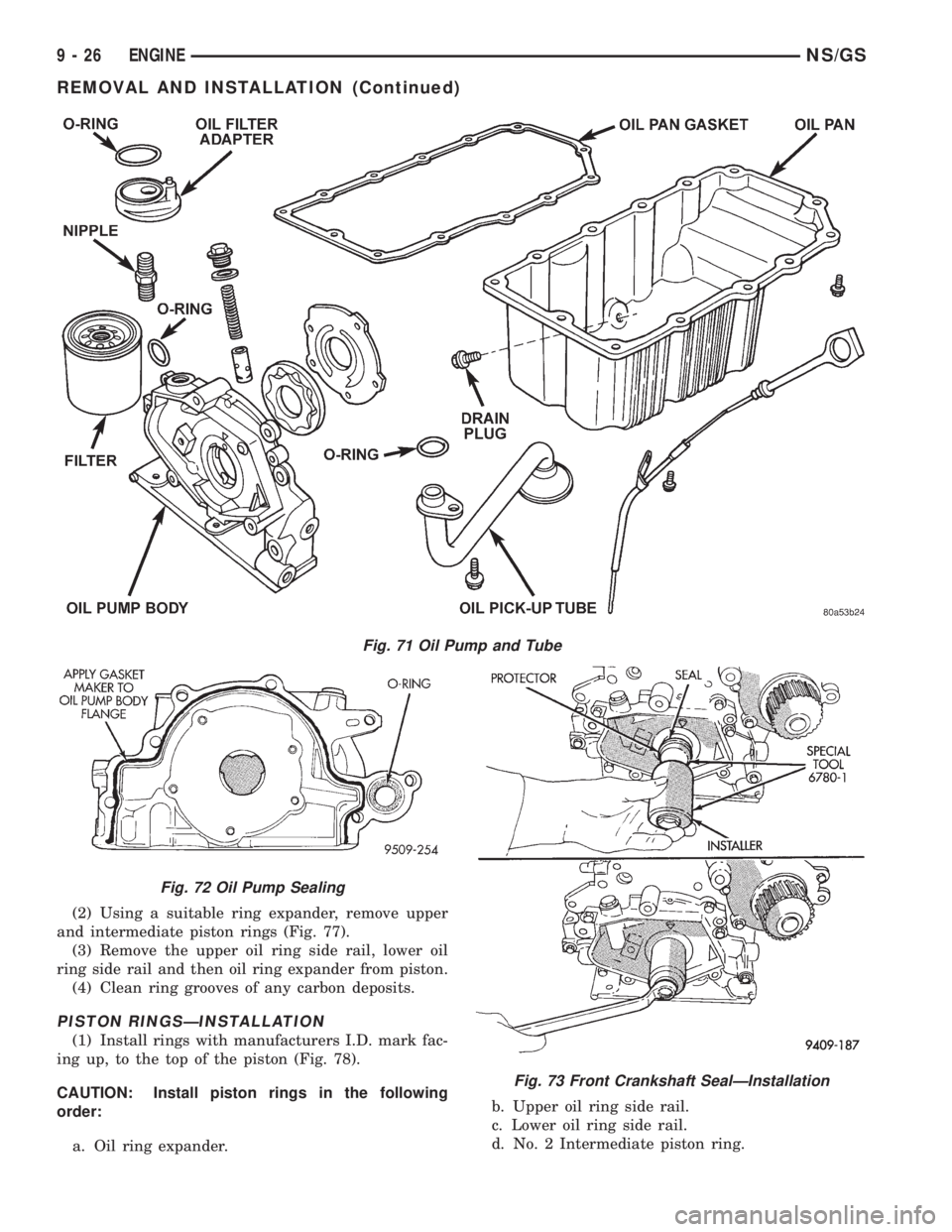
(2) Using a suitable ring expander, remove upper
and intermediate piston rings (Fig. 77).
(3) Remove the upper oil ring side rail, lower oil
ring side rail and then oil ring expander from piston.
(4) Clean ring grooves of any carbon deposits.
PISTON RINGSÐINSTALLATION
(1) Install rings with manufacturers I.D. mark fac-
ing up, to the top of the piston (Fig. 78).
CAUTION: Install piston rings in the following
order:
a. Oil ring expander.b. Upper oil ring side rail.
c. Lower oil ring side rail.
d. No. 2 Intermediate piston ring.
Fig. 71 Oil Pump and Tube
Fig. 72 Oil Pump Sealing
Fig. 73 Front Crankshaft SealÐInstallation
9 - 26 ENGINENS/GS
REMOVAL AND INSTALLATION (Continued)
Page 1205 of 1938
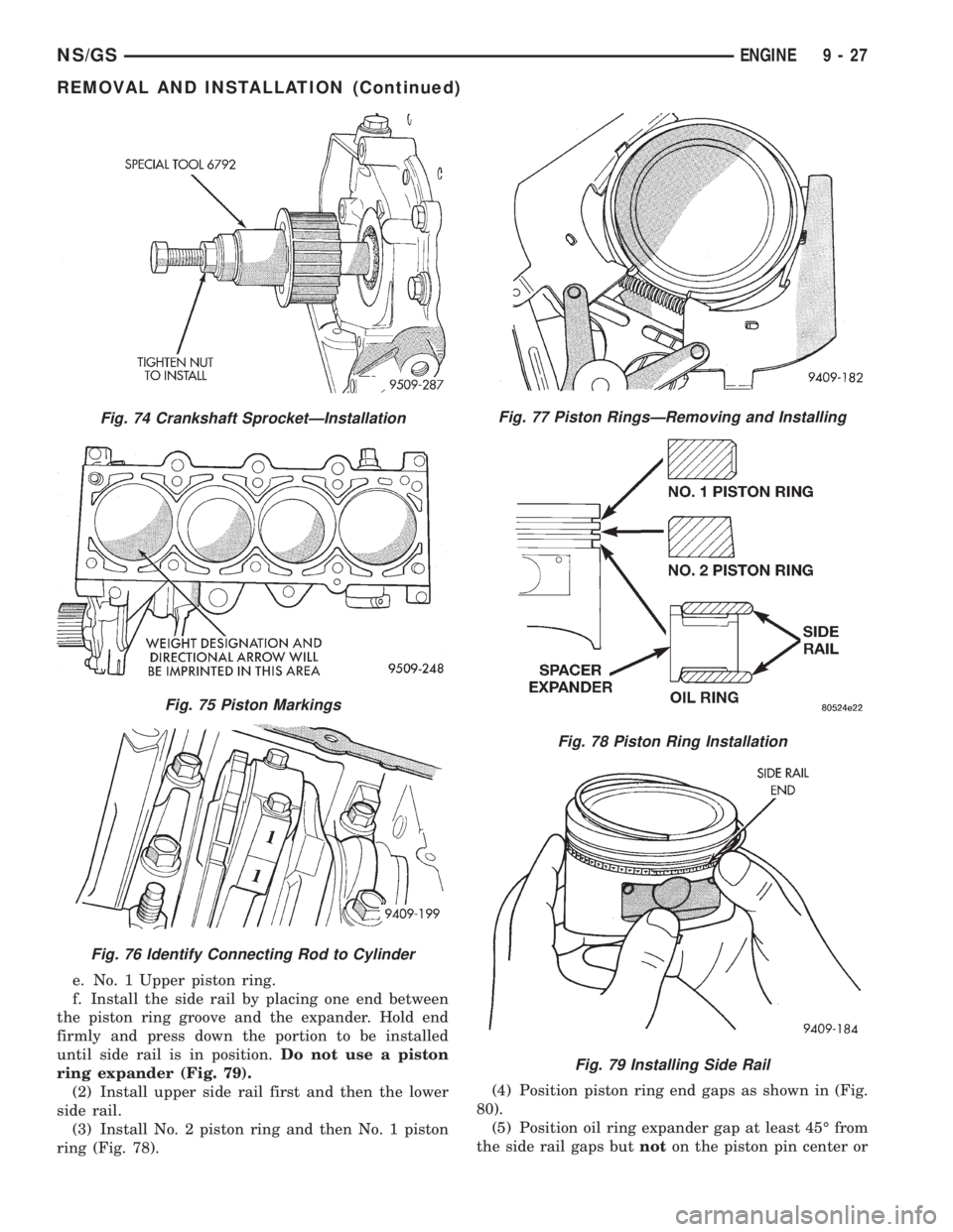
e. No. 1 Upper piston ring.
f. Install the side rail by placing one end between
the piston ring groove and the expander. Hold end
firmly and press down the portion to be installed
until side rail is in position.Do not use a piston
ring expander (Fig. 79).
(2) Install upper side rail first and then the lower
side rail.
(3) Install No. 2 piston ring and then No. 1 piston
ring (Fig. 78).(4) Position piston ring end gaps as shown in (Fig.
80).
(5) Position oil ring expander gap at least 45É from
the side rail gaps butnoton the piston pin center or
Fig. 74 Crankshaft SprocketÐInstallation
Fig. 75 Piston Markings
Fig. 76 Identify Connecting Rod to Cylinder
Fig. 77 Piston RingsÐRemoving and Installing
Fig. 78 Piston Ring Installation
Fig. 79 Installing Side Rail
NS/GSENGINE 9 - 27
REMOVAL AND INSTALLATION (Continued)