1996 CHRYSLER VOYAGER turn signal
[x] Cancel search: turn signalPage 419 of 1938

STEP IS NOT DONE A DIAGONSTIC TROUBLE
CODE (DTC) MAY BE SET.
VACUUM RESERVOIR
The reservoir contains a one-way check valve to
trap engine vacuum in the reservoir. When engine
vacuum drops, as in climbing a grade while driving,
the reservoir supplies the vacuum needed to main-
tain proper speed control operation. The vacuum res-
ervoir cannot be repaired and must be replaced if
faulty.
VEHICLE SPEED AND DISTANCE
The 4 speed automatic Transmission Control Mod-
ule (TCM) supplies the speed input to the PCM. The
PCM determines acceleration rates. The speed con-
trol software in the PCM uses vehicle speed and
acceleration to control to the set speed.
Vehicles with a 3 speed automatic or manual trans-
mission have a vehicle speed sensor (VSS) mounted
to an adapter near the transmission output shaft.
The sensor is driven through the adapter by a speed-
ometer pinion gear. The VSS pulse signal is moni-
tored by the PCM to determine vehicle speed and to
maintain speed control set speed. Refer to the appro-
priate Powertrain Diagnostic Procedures manual for
diagnosis and testing of this component. Refer to
group 14, Fuel System for Removal/Installation
DIAGNOSIS AND TESTING
ROAD TEST
Perform a vehicle road test to verify reports of
speed control system malfunction. The road test
should include attention to the speedometer. Speed-
ometer operation should be smooth and without flut-
ter at all speeds.
Flutter in the speedometer indicates a problem
which might cause surging in the speed control sys-
tem. The cause of any speedometer problems should
be corrected before proceeding. Refer to Group 8E,
Instrument Panel and Gauges for speedometer diag-
nosis.
If a road test verifies a surge following a set and
the speedometer operates properly see ªOvershoot/
Undershoot on speed control setº.
If a road test verifies an inoperative system, and
the speedometer operates properly, check for:
²A Diagnostic Trouble Code (DTC). If a DTC
exists, conduct tests per the Powertrain Diagnostic
Procedures service manual.
²A misadjusted brake (stop) lamp switch. This
could also cause an intermittent problem.
²Loose or corroded electrical connections at the
servo. Corrosion should be removed from electricalterminals and a light coating of Mopar Multipurpose
Grease, or equivalent, applied.
²Leaking vacuum reservoir.
²Loose or leaking vacuum hoses or connections.
²Defective one-way vacuum check valve.
²Secure attachment at both ends of the speed
control servo cable.
²Smooth operation of throttle linkage and throttle
body air valve.
²Conduct electrical test at PCM.
²Failed speed control servo. Do the servo vacuum
test.
CAUTION: When test probing for voltage or conti-
nuity at electrical connectors, care must be taken
not to damage connector, terminals or seals. If
these components are damaged, intermittent or
complete system failure may occur.
OVERSHOOT/UNDERSHOOT FOLLOWING SPEED
CONTROL SET
If the operator repeatedly presses and releases the
set button with their foot off of the accelerator (a ªlift
foot setº to begin speed control operation), the vehicle
may accelerate and exceed the desired set speed by
up to 5 MPH (8 km/h) and then decelerate to less
than the desired set speed before finally achieving
the desired set speed.
The Speed Control has an adaptive strategy that
compensates for vehicle-to-vehicle variations in speed
control cable lengths. When the speed control is set
with the vehicle operators foot off of the accelerator
pedal, the speed control thinks there is excessive
speed control cable slack and adapts. If the lift foot
sets are continually used, the speed control over-
shoot/undershoot condition will develop.
To ªunlearnº the overshoot/undershoot condition,
the vehicle operator has to press and release the set
button while maintaining the desired set speed with
the accelerator pedal (not decelerating or accelerat-
ing), and then turn the cruise control switch to the
OFF position (or press the CANCEL button if
equipped) after waiting 10 seconds. This procedure
must be performed approximately 10±15 times to
completely unlearn the overshoot/undershoot condi-
tion.
CHECKING FOR DIAGNOSTIC CODES
When trying to verify a speed control system elec-
tronic malfunction: Connect a DRB scan tool if avail-
able to the data link connector. The connector is
located at left side of the steering column, and at
lower edge of the panel.
(1) A speed control malfunction may occur without
a diagnostic code being indicated.
NSVEHICLE SPEED CONTROL SYSTEM 8H - 3
DESCRIPTION AND OPERATION (Continued)
Page 429 of 1938

TURN SIGNAL AND FLASHERS
CONTENTS
page page
GENERAL INFORMATION
COMBINATION FLASHER.................. 1
INTRODUCTION......................... 1
DESCRIPTION AND OPERATION
COMBINATION FLASHER / DAYTIME
RUNNING LAMPS (DRL) MODULE......... 2
COMBINATION FLASHER FUNCTION......... 1DIAGNOSIS AND TESTING
COMBINATION FLASHER WITH / WITHOUT
DAYTIME RUNNING LAMPS MODULEÐ
CIRCUIT DIAGNOSTICS.................. 3
TURN SIGNAL MULTI-FUNCTION SWITCH.... 2
REMOVAL AND INSTALLATION
COMBINATION FLASHER WITH / WITHOUT
DRL MODULE........................ 11
MULTI-FUNCTION SWITCH............... 11
GENERAL INFORMATION
INTRODUCTION
The turn signals are actuated with a lever on the
left side of the steering column just ahead of the
steering wheel. The signals are automatically turned
off by a canceling cam (two lobes molded to the clock-
spring mechanism). The cam comes in contact with
the cancel actuator on the turn signal (multi-func-
tion) switch assembly. Either cam lobe, pushing on
the cancel actuator, returns the switch to the OFF
position.
Lane change signaling is actuated by applying par-
tial turn signal stalk movement toward the direction
desired until the indicator lamps flashes in the
instrument cluster. When the switch stalk is released
the stalk will spring back into the neutral position
turning OFF the turn signal.
With the ignition switch ON and the turn signal
switch stalk actuated left or right, current flows
through the:
²Combination flasher
²Multi-function switch
²Turn indicator lamp
²Front and rear turn signal bulbs.
A chime will sound after the vehicle has traveled a
distance of approximately 0.5 mile with the turn sig-
nal ON.
COMBINATION FLASHER
The Turn Signal/Hazard Warning Flasher is a
module providing the vehicle with turn signal and
hazard warning functions and has been designed
with internal relays to take advantage of low current
switching requirements in the vehicle. It is plugged
into the Junction Block at position 4 (Fig. 1), where
all wiring associated with its operation is terminated.The Junction Block is adjacent to and left of the
steering column of the vehicle.
To gain access to the flasher, remove the lower
steering column cover and knee blocker. Refer to
Group 8E, Instrument Panel and Systems for
removal procedures.
DESCRIPTION AND OPERATION
COMBINATION FLASHER FUNCTION
The Turn Signal/Hazard Warning Flasher is a
module providing turn signal, hazard warning func-
tions and has been designed with internal relays to
Fig. 1 Combination Flasher Location
NSTURN SIGNAL AND FLASHERS 8J - 1
Page 430 of 1938

take advantage of low current switching require-
ments in the vehicle. It is plugged into the Junction
Block at positions 4 (Fig. 1) where all wiring associ-
ated with its operation is terminated. The Junction
Block is adjacent to and left of the steering column of
the vehicle.
To gain access to the device, remove the lower
steering column cover and knee blocker, refer to
Group 8E, Instrument Panel and Systems.
The combination flasher may be operated in its
hazard warning mode either with or without the igni-
tion circuit being active. However, in order to operate
in the turn signal mode, the ignition circuit must be
completed to the module.
While the combination flasher is idle, there is no
current drawn through the module. The device does
not become active until a signal ground circuit is
supplied to either of the turn signal inputs or the
hazard warning input.
Typical flash rate for the flasher is 90 flashes per
minute.
When a lamp is burnt out for a given side of the
vehicle or a wire is open to a lamp, the flash rate will
increase to 180 flashes per minute when in the turn
signal mode. When in the hazard warning signal
mode the flash rate remains at 90 flashes per
minute.
Turn signal inputs that actuate the flasher are low
current grounds, each drawing a maximum of 300
mA., and are provided to the flasher through the
Junction Block from the multi-function switch that is
mounted to the steering column. The hazard warning
signal input is a low current ground drawing a max-
imum of 600 mA. through the multi-function switch.
COMBINATION FLASHER / DAYTIME RUNNING
LAMPS (DRL) MODULE
The Combination Flasher/DRL is a module provid-
ing turn signal, hazard warning, and daytime run-
ning light functions, and has been designed with
internal relays to take advantage of low current
switching requirements in the vehicle. It is plugged
into the junction block at positions 3 AND 4 (Fig. 2)
where all wiring associated with its operation is ter-
minated. The Junction Block is adjacent to and left of
the steering column of the vehicle.
To gain access to the device, remove the lower
steering column cover and knee blocker, refer to
Group 8E, Instrument Panel and Gauges.
The combination flasher/DRL may be operated in
its hazard warning mode either with or without the
ignition circuit being active. However, in order to
operate in the turn signal mode or the DRL mode,
the ignition circuit must be completed to the module.
While the combination flasher portion is idle, there
is no current drawn through the module. The devicedoes not become active in the turn signal or hazard
warning modes until a signal ground circuit is sup-
plied to either of the turn signal inputs or the hazard
warning input. With the ignition OFF, there is no
current drawn through the module.
While the ignition is ON, the front turn signal fil-
aments are illuminated steadily thus providing the
DRL function. The DRL function may be inhibited by
applying a signal ground input from either the park
brake circuit or the headlamp relay activation circuit.
Typical flash rate for the flasher is 90 flashes per
minute.
When a lamp is burnt out for a given side of the
vehicle or a wire is open to a lamp, the flash rate will
increase to 180 flashes per minute when in the turn
signal mode. When in the hazard warning signal
mode the flash rate remains at 90 flashes per
minute.
Turn signal inputs that actuate the flasher are low
current grounds, each could draw a maximum of 300
mA., and are provided to the flasher through the
Junction Block from the multi-function switch that is
mounted to the steering column. The hazard warning
signal input is a low current ground that could draw
a maximum of 600 mA. through the multi-function
switch.
DIAGNOSIS AND TESTING
TURN SIGNAL MULTI-FUNCTION SWITCH
To test turn signal, headlamp beam select and opti-
cal horn portion of the multi-function switch:
(1) Remove the multi-function switch, refer to
removal procedures.
(2) Using an ohmmeter check continuity reading
between multi-function switch pins. Refer to (Fig. 3)
for proper pin numbers and Turn Signal Multi-Func-
tion Switch Test chart.
Fig. 2 Junction Block Terminal Pins
8J - 2 TURN SIGNAL AND FLASHERSNS
DESCRIPTION AND OPERATION (Continued)
Page 431 of 1938

COMBINATION FLASHER WITH / WITHOUT
DAYTIME RUNNING LAMPS MODULEÐCIRCUIT
DIAGNOSTICS
The battery input (Pin 1), is brought into the Junction
Block through the Electrical Distribution Wiring (EDW)
harness (Fig. 4). It originates under the hood in thePower Distribution Center (PDC) through a 20 ampere
fuse at position 10 (9th position from the upper end) and
labeled HAZARD. This circuit (L09) is the only power
feed to the combination-flasher/DRL.
The ignition input of Pin 6 (refer to Junction Block
Terminal Call-Out and Junction Block Terminal Call-Out
with DRL tables) only senses that the ignition circuit is
ON and does not supply current to the module in a way
that would power the system. This RUN/START circuit is
brought into the junction block to a 10 ampere fuse
labeled TS BU LMP at the bottom right side. The circuit
designation out of the fuse is A22D. This circuit feeds the
combo-flasher and the following systems with Ignition
voltage if the vehicle is so equipped:
²Back-Up Lamps
²Electrochromic Inside Rear view Mirror
²A/C Control Head
²Mini-Trip Computer
²ABS Module
²Front Blower Relay Coil
²Rear Blower Relay Coil
²AWD Solenoids
²Rear Window Defogger (EBL) Relay Coil
The ignition input to the combo-flasher will draw
typically 5 mA of current while active.
For diagnostic test procedures, refer to Combina-
tion Flasher Diagnosis tables.
Fig. 4 Electronic Combination Flasher Circuit
Fig. 3 Turn Signal±Multi-Function Switch Pin
numbers
TURN SIGNAL MULTI-FUNCTION SWITCH
TEST
SWITCH POSITIONCONTINUITY
BETWEEN
LEFT 4 AND 8
RIGHT 3 AND 8
HAZARD 1 AND 8
LO BEAM 9 AND 10
HI BEAM 9 AND 121
NSTURN SIGNAL AND FLASHERS 8J - 3
DIAGNOSIS AND TESTING (Continued)
Page 432 of 1938

Fig. 5 Electronic Combination Flasher with DRL Circuit
JUNCTION BLOCK TERMINAL CALL-OUT
CAV. CKT. WIRE
GAUGECOLOR FUNCTION
1 L09 18 BLK/WT BATTERY INTPUT MAIN FEED
2 L61 18 LG LEFT FRONT T/S OUTPUT TO LAMP
3 L60 18 TN RIGHT FRONT T/S OUTPUT TO LAMP
4 L63 18 DG/RD LEFT REAR T/S OUTPUT TO LAMP
5 L62 18 BR/RD RIGHT REAR T/S OUTPUT TO LAMP
6 A22D 20 BK/OR IGNITION INPUT SENSE ONLY
7 L305 22 LB/WT LEFT T/S SWITCH INPUT SENSE ONLY
8 L302 22 LB/YL RIGHT T/S SWITCH INPUT SENSE ONLY
9 L91 22 DB/PK HAZARD SWITCH INPUT SENSE ONLY
8J - 4 TURN SIGNAL AND FLASHERSNS
DIAGNOSIS AND TESTING (Continued)
Page 433 of 1938

JUNCTION BLOCK TERMINAL CALL-OUT WITH DRL
CAV. CKT. WIRE
GAUGECOLOR FUNCTION
1 L09 18 BLK/WT BATTERY INTPUT MAIN FEED
2 L61 18 LG LEFT FRONT T/S OUTPUT TO LAMP
3 L60 18 TN RIGHT FRONT T/S OUTPUT TO LAMP
4 L63 18 DG/RD LEFT REAR T/S OUTPUT TO LAMP
5 L62 18 BR/RD RIGHT REAR T/S OUTPUT TO LAMP
6 A22D 20 BK/OR IGNITION INPUT SENSE ONLY
7 L305 22 LB/WT LEFT T/S SWITCH INPUT SENSE ONLY
8 L302 22 LB/YL RIGHT T/S SWITCH INPUT SENSE ONLY
9 L91 22 DB/PK HAZARD SWITCH INPUT SENSE ONLY
10 G09 22 GY/BK PARK BRAKE SWITCH INPUT SENSE ONLY
11 Z01 14 BK GROUND MAIN GRD.
12 L93 22 RD/YL HEADLAMP RELAY SWITCH
INPUTSENSE ONLY
NSTURN SIGNAL AND FLASHERS 8J - 5
DIAGNOSIS AND TESTING (Continued)
Page 434 of 1938
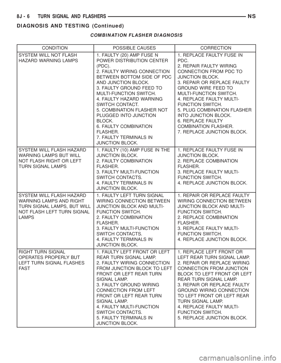
COMBINATION FLASHER DIAGNOSIS
CONDITION POSSIBLE CAUSES CORRECTION
SYSTEM WILL NOT FLASH
HAZARD WARNING LAMPS1. FAULTY (20) AMP FUSE N
POWER DISTRIBUTION CENTER
(PDC).
2. FAULTY WIRING CONNECTION
BETWEEN BOTTOM SIDE OF PDC
AND JUNCTION BLOCK.
3. FAULTY GROUND FEED TO
MULTI-FUNCTION SWITCH.
4. FAULTY HAZARD WARNING
SWITCH CONTACT.
5. COMBINATION FLASHER NOT
PLUGGED INTO JUNCTION
BLOCK.
6. FAULTY COMBINATION
FLASHER.
7. FAULTY TERMINALS IN
JUNCTION BLOCK.1. REPLACE FAULTY FUSE IN
PDC.
2. REPAIR FAULTY WIRING
CONNECTION FROM PDC TO
JUNCTION BLOCK.
3. REPAIR OR REPLACE FAULTY
GROUND WIRE FEED TO
MULTI-FUNCTION SWITCH.
4. REPLACE FAULTY MULTI-
FUNCTION SWITCH.
5. PLUG COMBINATION FLASHER
INTO JUNCTION BLOCK.
6. REPLACE FAULTY
COMBINATION FLASHER.
7. REPLACE JUNCTION BLOCK.
SYSTEM WILL FLASH HAZARD
WARNING LAMPS BUT WILL
NOT FLASH RIGHT OR LEFT
TURN SIGNAL LAMPS1. FAULTY (10) AMP FUSE IN THE
JUNCTION BLOCK.
2. FAULTY COMBINATION
FLASHER.
3. FAULTY MULTI-FUNCTION
SWITCH CONTACTS.
4. FAULTY TERMINALS IN
JUNCTION BLOCK.1. REPLACE FAULTY FUSE IN
JUNCTION BLOCK.
2. REPLACE COMBINATION
FLASHER.
3. REPLACE FAULTY MULTI-
FUNCTION SWITCH.
4. REPLACE JUNCTION BLOCK.
SYSTEM WILL FLASH HAZARD
WARNING LAMPS AND RIGHT
TURN SIGNAL LAMPS, BUT WILL
NOT FLASH LEFT TURN SIGNAL
LAMPS1. FAULTY LEFT TURN SIGNAL
WIRING CONNECTION BETWEEN
JUNCTION BLOCK AND MULTI-
FUNCTION SWITCH.
2. FAULTY COMBINATION
FLASHER.
3. FAULTY MULTI-FUNCTION
SWITCH CONTACTS.
4. FAULTY TERMINALS IN
JUNCTION BLOCK.1. REPAIR OR REPLACE FAULTY
WIRING CONNECTION BETWEEN
JUNCTION BLOCK AND MULTI-
FUNCTION SWITCH.
2. REPLACE COMBINATION
FLASHER.
3. REPLACE FAULTY MULTI-
FUNCTION SWITCH.
4. REPLACE JUNCTION BLOCK.
RIGHT TURN SIGNAL
OPERATES PROPERLY BUT
LEFT TURN SIGNAL FLASHES
FAST1. FAULTY LEFT FRONT OR LEFT
REAR TURN SIGNAL LAMP.
2. FAULTY WIRING CONNECTION
FROM JUNCTION BLOCK TO LEFT
FRONT OR LEFT REAR TURN
SIGNAL LAMP.
3. FAULTY GROUND WIRING
CONNECTION FROM LEFT
FRONT OR LEFT REAR TURN
SIGNAL LAMP.
4. FAULTY MULTI-FUNCTION
SWITCH CONTACTS.
5. FAULTY TERMINALS IN
JUNCTION BLOCK.1. REPLACE LEFT FRONT OR
LEFT REAR TURN SIGNAL LAMP.
2. REPAIR OR REPLACE WIRING
CONNECTION FROM JUNCTION
BLOCK TO LEFT FRONT OR LEFT
REAR TURN SIGNAL LAMP.
3. REPAIR OR REPLACE FAULTY
GROUND WIRING CONNECTION
TO LEFT FRONT OR LEFT REAR
TURN SIGNAL LAMP.
4. REPLACE FAULTY MULTI-
FUNCTION SWITCH.
5. REPLACE JUNCTION BLOCK.
8J - 6 TURN SIGNAL AND FLASHERSNS
DIAGNOSIS AND TESTING (Continued)
Page 435 of 1938

CONDITION POSSIBLE CAUSES CORRECTION
LEFT TURN SIGNAL OPERATES
PROPERLY BUT RIGHT TURN
SIGNAL FLASHES FAST1. FAULTY RIGHT FRONT OR
RIGHT REAR TURN SIGNAL LAMP.
2. FAULTY WIRING CONNECTION
FROM JUNCTION BLOCK TO
RIGHT FRONT OR RIGHT REAR
TURN SIGNAL LAMP.
3. FAULTY GROUND WIRING
CONNECTION FROM RIGHT
FRONT OR RIGHT REAR TURN
SIGNAL LAMP.
4. FAULTY MULTI-FUNCTION
SWITCH CONTACTS.
5. FAULTY TERMINALS IN
JUNCTION BLOCK.1. REPLACE RIGHT FRONT OR
RIGHT REAR TURN SIGNAL LAMP.
2. REPAIR OR REPLACE WIRING
CONNECTION FROM JUNCTION
BLOCK TO RIGHT FRONT OR
RIGHT REAR TURN SIGNAL LAMP.
3. REPAIR OR REPLACE FAULTY
GROUND WIRING CONNECTION
TO RIGHT FRONT OR RIGHT
REAR TURN SIGNAL LAMP.
4. REPLACE FAULTY MULTI-
FUNCTION SWITCH.
5. REPLACE JUNCTION BLOCK.
BOTH TURN SIGNAL
INDICATORS IN MESSAGE
CENTER DO NOT FLASH IN
CONJUNCTION WITH OUTSIDE
TURN SIGNAL LAMPS1. FAULTY GROUND WIRING
CONNECTION FROM COWL
GROUND SPLICE.1. REPAIR OR REPLACE WIRING
CONNECTION FROM COWL
GROUND SPLICE.
LEFT OR RIGHT TURN SIGNAL
INDICATOR IN MESSAGE
CENTER DOES NOT FLASH IN
CONJUNCTION WITH OUTSIDE
TURN SIGNAL LAMPS, BUT
OTHER INDICATOR PERFORMS
PROPERLY1. FAULTY INDICATOR LAMP IN
MESSAGE CENTER.
2. FAULTY WIRING CONNECTION
BETWEEN MESSAGE CENTER
AND JUNCTION BLOCK.1. REPLACE FAULTY INDICATOR
LAMP IN MESSAGE CENTER.
2. REPAIR OR REPLACE FAULTY
WIRING CONNECTION BETWEEN
MESSAGE CENTER AND
JUNCTION BLOCK.
NSTURN SIGNAL AND FLASHERS 8J - 7
DIAGNOSIS AND TESTING (Continued)