1996 CHRYSLER VOYAGER gas type
[x] Cancel search: gas typePage 244 of 1938

THERMOSTAT OPERATION
2.5 VM DIESEL
The engine cooling thermostats are wax pellet
driven, reverse poppet choke type. They are designed
to provide the fastest warm up possible by prevent-
ing leakage through them and to guarantee a mini-
mum engine operating temperature (Fig. 10). The
thermostat has a hole to bleed off air in the cooling
system during engine warm up. The thermostat
begins to open at 80É C62É (176É F64É).
PRESSURE/VENT CAP
WARNING: Engine coolant can reach temperatures
of 200É fahrenheit or greater. If the cooling system
is opened with coolant at a high temperature, hot
coolant can be forced out of the system under high
pressures, causing personal injury. Allow system to
cool down prior to removing the pressure cap.
The pressure/vent cap is secured to the coolant
tank neck by a means of a cam lock system. This cap
releases excess pressure at some point within a
range of 90-117 kPa (13- 17 psi) for gasoline engines,
and 110±124 kPa (16±18 psi) for diesel engines. The
actual pressure relief point (in pounds) is labeled on
top of the cap (Fig. 11).
The cooling system will operate at pressures
slightly above atmospheric pressure. This results in a
higher coolant boiling point allowing increased radi-
ator cooling capacity. The cap (Fig. 11) contains a
spring-loaded pressure relief valve. This valve opens
when system pressure reaches approximately 103
kPa (15 psi).
When the engine is cooling down, vacuum is
formed within the cooling system. To prevent collapse
of the radiator and coolant hoses from this vacuum, a
vacuum valve is used within the cap. This valve pre-
vents excessive pressure differences from occurring
between the closed cooling system and the atmo-
sphere. If the vacuum valve is stuck shut, the radia-
tor and/or cooling system hoses will collapse on cool-
down.
Fig. 7 Water PumpÐ2.0L Gasoline Engine
Fig. 8 Water PumpÐ2.0L Gasoline Engine
Fig. 9 Water PumpÐ2.5L VM Diesel
Fig. 10 Thermostat and Housing Ð 2.5L VM Diesel
7 - 4 COOLING SYSTEMNS/GS
DESCRIPTION AND OPERATION (Continued)
Page 247 of 1938

SERVICE PROCEDURES
ADDING ADDITIONAL COOLANT
2.5L VM DIESEL
Do not remove coolant bottle pressure cap when
the engine is hot. Remove pressure cap and fill cool-
ant bottle between Min and Max lines inside filler
neck. Use only 50/50 mix of ethylene glycol type anti-
freeze and water (Fig. 13). Squeezing radiator hoses
may help purge air from the cooling system.
DRAINING COOLING SYSTEM
2.0L GASOLINE
To drain cooling system move temperature selector
for heater to full heat with engine running.Without
removing radiator pressure cap and with sys-
tem not under pressure,Shut engine off and open
draincock. The coolant reserve tank should empty
first, then remove radiator pressure cap and let the
radiator drain (if not, see Testing Cooling System for
leaks).
2.5L VM DIESEL
The cooling system does not have a radiator
mounted pressure cap. Instead the pressure cap is
mounted on the coolant pressure bottle (Fig. 14).
(1) Shut off engine.
(2) Remove radiator pressure cap.
(3) Open draincock and allow coolant to drain.
REFILLING COOLING SYSTEM
2.0L GASOLINE
Refer to the gasoline engine cooling system infor-
mation in this manual. Cooling system capacity is 6.0
liters (6.34 qts.) which includes the heater and cool-
ant recovery tank.
2.5L VM DIESEL
First clean system to remove old glycol, see Cooling
System Cleaning.
(1) Disconnect upper radiator hose at thermostat
housing.
(2) Remove pressure cap from coolant expansion
tank.
(3) Fill cooling system through upper radiator hose
until coolant starts to leak out at the thermostat
housing. Reconnect hose and re-install clamp.
(4) Fill expansion tank to top of bottle. Run engine
at idle without pressure cap installed for 5 minutes.
Squeeze upper radiator hose several times.
(5) Shut off engine. Top off coolant and install
pressure cap.
(6) Inspect system for leaks.
REMOVAL AND INSTALLATION
WATER PUMP Ð 2.0L GASOLINE
REMOVAL
(1) Remove accessory drive belts and power steer-
ing pump.
(2) Drain cooling system.
Fig. 13 Coolant Pressure BottleÐ2.5L VM Diesel
Fig. 14 Pressure Cap and BottleÐVM Diesel
NS/GSCOOLING SYSTEM 7 - 7
Page 253 of 1938

BATTERY
CONTENTS
page page
GENERAL INFORMATION
INTRODUCTION......................... 1
SAFETY PRECAUTIONS AND WARNINGS..... 1
DESCRIPTION AND OPERATION
BATTERY IGNITION OFF DRAW (IOD)........ 1
CHARGING TIME REQUIRED............... 2
DIAGNOSIS AND TESTING
BATTERY BUILT-IN TEST INDICATOR........ 2
BATTERY IGNITION OFF DRAW (IOD)........ 3
BATTERY LOAD TEST..................... 4
BATTERY OPEN CIRCUIT VOLTAGE TEST..... 6SERVICE PROCEDURES
BATTERY CHARGING..................... 6
CHARGING COMPLETELY DISCHARGED
BATTERY............................. 7
VISUAL INSPECTION..................... 7
REMOVAL AND INSTALLATION
BATTERY TRAY.......................... 9
BATTERY............................... 8
SPECIFICATIONS
BATTERY SPECIFICATIONS............... 10
TORQUE.............................. 10
GENERAL INFORMATION
INTRODUCTION
The battery stores, stabilizes, and delivers electri-
cal current to operate various electrical systems in
the vehicle. The determination of whether a battery
is good or bad is made by its ability to accept a
charge. It also must supply high-amperage current
for a long enough period to be able to start the vehi-
cle. The capability of the battery to store electrical
current comes from a chemical reaction. This reac-
tion takes place between the sulfuric acid solution
(electrolyte) and the lead +/- plates in each cell of the
battery. As the battery discharges, the plates react
with the acid from the electrolyte. When the charging
system charges the battery, the water is converted to
sulfuric acid in the battery. The concentration of acid
in the electrolyte is measured as specific gravity
using a hydrometer. The original equipment (OE)
battery is equipped with a hydrometer (test indica-
tor) built into the battery cover. The specific gravity
indicates the battery's state-of-charge. The OE bat-
tery is sealed and water cannot be added.
The battery is vented to release gases that are cre-
ated when the battery is being charged and dis-
charged. The battery top, posts, and terminals should
be cleaned when other under hood maintenance is
performed.
When the electrolyte level is below the top of the
plates, Clear in the test Indicator, the battery must
be replaced. The battery must be completely charged,
and the battery top, posts, and cable clamps must be
cleaned before diagnostic procedures are performed.
SAFETY PRECAUTIONS AND WARNINGS
WARNING: DO NOT ALLOW JUMPER CABLE
CLAMPS TO TOUCH EACH OTHER WHEN CON-
NECTED TO A BOOSTER SOURCE. DO NOT USE
OPEN FLAME NEAR BATTERY. REMOVE METALLIC
JEWELRY WORN ON HANDS OR WRISTS TO AVOID
INJURY BY ACCIDENTAL ARCING OF BATTERY
CURRENT.
WHEN USING A HIGH OUTPUT BOOSTING DEVICE,
DO NOT ALLOW THE DISABLED VEHICLE'S BAT-
TERY TO EXCEED 16 VOLTS. PERSONAL INJURY
OR DAMAGE TO ELECTRICAL SYSTEM CAN
RESULT.
TO PROTECT THE HANDS FROM BATTERY ACID, A
SUITABLE PAIR OF HEAVY DUTY RUBBER
GLOVES, NOT THE HOUSEHOLD TYPE, SHOULD
BE WORN WHEN REMOVING OR SERVICING A
BATTERY. SAFETY GLASSES ALSO SHOULD BE
WORN.
DESCRIPTION AND OPERATION
BATTERY IGNITION OFF DRAW (IOD)
A completely normal vehicle will have a small
amount of current drain on the battery with the key
out of the ignition. It can range from 5 to 25 milli-
amperes after all the modules time out. If a vehicle
will not be operated for approximately a 20 days, the
IOD fuse should be pulled to eliminate the vehicle
electrical drain on the battery. The IOD fuse is
NSBATTERY 8A - 1
Page 1051 of 1938
ENGINE
CONTENTS
page page
2.4L ENGINE............................ 14
3.0L ENGINE............................ 61
3.3/3.8L ENGINE........................ 93ENGINE DIAGNOSIS....................... 7
STANDARD SERVICE PROCEDURES.......... 1
STANDARD SERVICE PROCEDURES
INDEX
page page
GENERAL INFORMATION
CRANKSHAFT SPROCKET BOLT ACCESS
PLUG................................ 2
ENGINE CORE PLUGS.................... 2
ENGINE OIL SERVICE..................... 5
ENGINE OIL............................. 5
ENGINE PERFORMANCE.................. 2FORM-IN-PLACE GASKETS................. 1
HONING CYLINDER BORES................ 3
HYDROSTATIC LOCKED ENGINE............ 5
MEASURING MAIN BEARING AND
CONNECTING ROD BEARING
CLEARANCES......................... 3
REPAIR OF DAMAGED OR WORN THREADS . . . 4
GENERAL INFORMATION
FORM-IN-PLACE GASKETS
There are numerous places where form-in-place
gaskets are used on the engine. Care must be taken
when applying form-in-place gaskets.Do not use
form-in-place gasket material unless specified.
Bead size, continuity, and location are of great impor-
tance. Too thin a bead can result in leakage while too
much can result in spill-over, a continuous bead of
the proper width is essential to obtain a leak-free
joint.
Two types of form-in-place gasket materials are
used in the engine.MopartSilicone Rubber Adhe-
sive Sealant andMopartGasket Maker, (anaerobic)
each have different properties and cannot be used
interchangeably.
CAUTION: Silicone sealer and anaerobic sealers
each will inhibit the cure of the other and care
should be taken to keep usages separated as much
as possible.
MOPARTSILICONE RUBBER ADHESIVE
SEALANT
MopartSilicone Rubber Adhesive Sealant or
equivalent, normally black in color, is available in
three ounce tubes. Moisture in the air causes the
MopartSilicone Rubber Adhesive Sealant material
to cure. This material is normally used on flexible
metal flanges. It has a shelf life of one year and will
not properly cure if over age. Always inspect the
package for the expiration date before use.
MOPARTGASKET MAKER
MopartGasket Maker is an anaerobic type gasket
material normally red in color. The material cures in
the absence of air when squeezed between two metal-
lic surfaces. It will not cure if left in the uncovered
tube. It is normally red in color. The anaerobic mate-
rial is for use between two machined surfaces. Do not
use on flexible metal flanges.
MOPARTTORQUE CURE GASKET MAKER
MopartTorque Cure Gasket Maker is a unique
anaerobic type gasket material to be usedONLY
between the bedplate and engine block. The material
cures in the absence of air when torqued between
two metallic surfaces. It will not cure if left in the
uncovered tube. This anaerobic material is specially
NSENGINE 9 - 1
Page 1056 of 1938
API SERVICE GRADE CERTIFIED
Use an engine oil that is API Service Grade Certi-
fied. MOPARtprovides engine oils that conforms to
this service grade.
SAE VISCOSITY
An SAE viscosity grade is used to specify the vis-
cosity of engine oil. Use only, engine oils with multi-
ple viscosities such as 5W-30 or 10W-30. These are
specified with a dual SAE viscosity grade which indi-
cates the cold-to-hot temperature viscosity range.
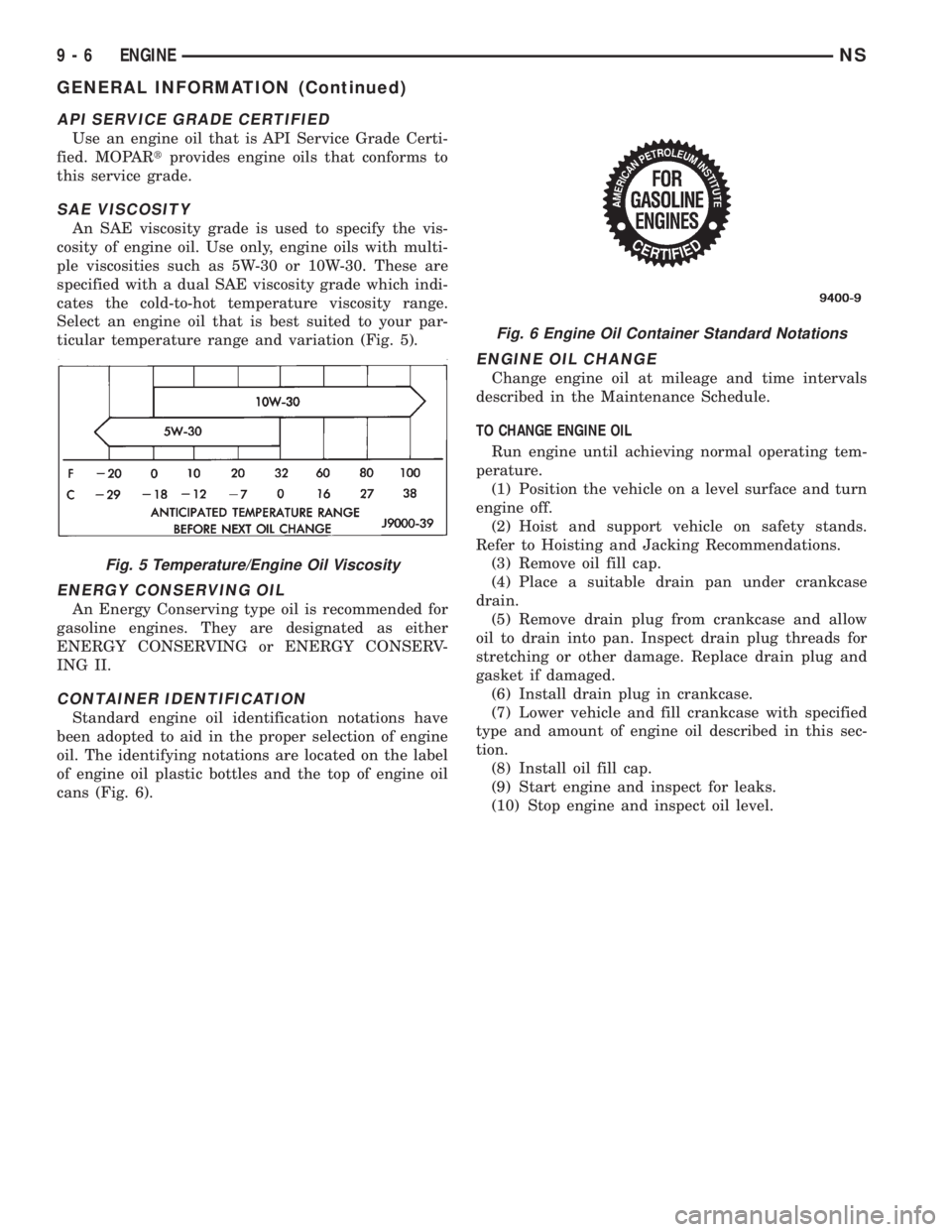
Select an engine oil that is best suited to your par-
ticular temperature range and variation (Fig. 5).
ENERGY CONSERVING OIL
An Energy Conserving type oil is recommended for
gasoline engines. They are designated as either
ENERGY CONSERVING or ENERGY CONSERV-
ING II.
CONTAINER IDENTIFICATION
Standard engine oil identification notations have
been adopted to aid in the proper selection of engine
oil. The identifying notations are located on the label
of engine oil plastic bottles and the top of engine oil
cans (Fig. 6).
ENGINE OIL CHANGE
Change engine oil at mileage and time intervals
described in the Maintenance Schedule.
TO CHANGE ENGINE OIL
Run engine until achieving normal operating tem-
perature.
(1) Position the vehicle on a level surface and turn
engine off.
(2) Hoist and support vehicle on safety stands.
Refer to Hoisting and Jacking Recommendations.
(3) Remove oil fill cap.
(4) Place a suitable drain pan under crankcase
drain.
(5) Remove drain plug from crankcase and allow
oil to drain into pan. Inspect drain plug threads for
stretching or other damage. Replace drain plug and
gasket if damaged.
(6) Install drain plug in crankcase.
(7) Lower vehicle and fill crankcase with specified
type and amount of engine oil described in this sec-
tion.
(8) Install oil fill cap.
(9) Start engine and inspect for leaks.
(10) Stop engine and inspect oil level.
Fig. 5 Temperature/Engine Oil Viscosity
Fig. 6 Engine Oil Container Standard Notations
9 - 6 ENGINENS
GENERAL INFORMATION (Continued)
Page 1112 of 1938
front seal is retained in the oil pump case and the
rear is retained in a block-mounted housing.
PISTONS:Are aluminum alloy with a steel strut,
short height, and thin wall so as to be autothermic
and light weight. The piston head with valve
recesses, in combination with the cylinder head,
forms a compact spherical head with clearance for
total valve lift with pistons at top dead center. The
piston skirt, top and second ring lands are finished to
a tapered roughness for oil retention and high resis-
tance to scuffing. Piston pins, pressed into place, join
the pistons to the connecting rods.
CYLINDER HEAD:The alloy cylinder heads fea-
ture cross-flow type intake and exhaust ports. Valve
guides and inserts are hardened cast iron. Valves of
heat resistance steel are arranged in a V with each
camshaft on center. To improve combustion speed the
chambers are a compact spherical design with a
squish area of approximately 30 percent of the piston
top area. The cylinder heads are common to either
cylinder bank by reversing the direction of installa-
tion.
CAMSHAFTS:Two overhead camshafts provide
valve actuation, one front (radiator side of cylinder
bank) and one rear. The front camshaft is provided
with a distributor drive and is longer. Both cam-
shafts are supported by four bearing journals, thrust
for the front camshaft is taken at journal two and
the rear at journal three. Front and rear camshaft
driving sprockets are interchangeable. The sprockets
and the engine water pump are driven by a single
notched timing belt.
ROCKER ARM SHAFTS:The shafts are retained
by the camshaft bearing journal caps. Four shafts are
used, one for each intake and exhaust rocker arm
assembly on each cylinder head. The hollow shafts
provide a duct for lubricating oil flow from the cylin-
der head to the valve mechanisms.
ROCKER ARMS:Are of light weight die-cast with
roller type follower operating against the cam shaft.
The valve actuating end of the rocker arms are
machined to retain hydraulic lash adjusters, elimi-
nating valve lash adjustment.
VALVES:Are made of heat resistant steel, valve
springs are especially designed to be short. The valve
spring wire cross-section is oval shaped and provides
the same spring tension as longer springs. Valve
spring retainers, locks and seals are conventional.
INTAKE MANIFOLD:The aluminum alloy mani-
fold is a cross type with long runners to improve
inertia. The runners, attaching below at the cylinder
head, also attach above and support an air plenum.
The air plenum chamber absorbs air pulsations cre-
ated during the suction phase of each cylinder.
EXHAUST MANIFOLDS:Both manifolds are a
log style made of ductile cast iron. Exhaust gasses,collected from the front cylinder bank, leave the front
manifold through an end outlet and are fed through
an upper crossover tube to the rear manifold. The
collected exhaust from both manifolds are combined,
and exit to the exhaust pipe through an articulated
joint.
DIAGNOSIS AND TESTING
CHECKING ENGINE OIL PRESSURE
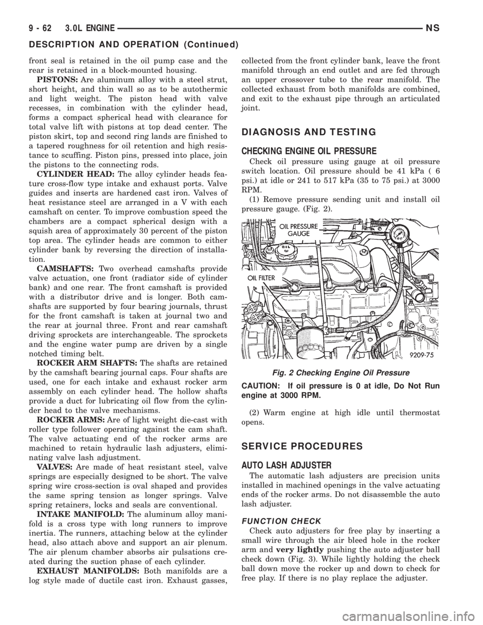
Check oil pressure using gauge at oil pressure
switch location. Oil pressure should be 41 kPa ( 6
psi.) at idle or 241 to 517 kPa (35 to 75 psi.) at 3000
RPM.
(1) Remove pressure sending unit and install oil
pressure gauge. (Fig. 2).
CAUTION: If oil pressure is 0 at idle, Do Not Run
engine at 3000 RPM.
(2) Warm engine at high idle until thermostat
opens.
SERVICE PROCEDURES
AUTO LASH ADJUSTER
The automatic lash adjusters are precision units
installed in machined openings in the valve actuating
ends of the rocker arms. Do not disassemble the auto
lash adjuster.
FUNCTION CHECK
Check auto adjusters for free play by inserting a
small wire through the air bleed hole in the rocker
arm andvery lightlypushing the auto adjuster ball
check down (Fig. 3). While lightly holding the check
ball down move the rocker up and down to check for
free play. If there is no play replace the adjuster.
Fig. 2 Checking Engine Oil Pressure
9 - 62 3.0L ENGINENS
DESCRIPTION AND OPERATION (Continued)
Page 1139 of 1938
SPECIFICATIONS
3.0L ENGINE
Type.........................60É V-6 SOHC
Number of Cylinders.......................6
Bore.....................91.1 mm (3.587 in.)
Stroke.....................76mm(2.992 in.)
Compression Ratio.....................8.85:1
Displacement..............3.0L (181 Cubic in.)
Firing Order....................1±2±3±4±5±6
Basic Ignition Timing.........Refer to Emission
Control Information Label on Vehicle
Compression Pressure...............1227 kPa
(178 psi) @ 250 RPM
Maximum Variation Between Cylinders......25%
Valve Timing
Intake Valve±Open.................19É BTDC
Intake Valve±Closed................59É ABDC
Exhaust Valve±Open................59É BBDC
Exhaust Valve±Closed...............19É ATDC
Cylinder Block
Cylinder Bore Diameter......91.1 mm (3.587 in.)
Top Surface Flatness........0.05 mm (0.002 in.)
Service Limit.............0.1 mm (0.0039 in.)
Grinding Limit of Top Surface*..........0.2 mm
(0.008 in.)
*Includes/Combined with cylinder Head Grinding
Pistons
Piston Diameter.................91.06 - 91.09
Piston to Cylinder Clearance......0.03 - 0.05 mm
(0.0012 - 0.002 in.)
Piston Ring End Gap No. 1......0.30 - 0.45 mm
(0.012 - 0.018 in.)
Service Limit..............0.8 mm (0.031 in.)
Piston Ring End Gap No. 2......0.45 - 0.60 mm
(0.018 - 0.024 in.)
Service Limit..............0.8 mm (0.031 in.)
Piston Ring End Gap Oil Control . .0.20 - 0.60 mm
(0.008 - 0.024 in.)
Service Limit..............1.0 mm (0.039 in.)
Ring Side Clearance No. 1......0.030 - 0.090 mm
(0.002 - 0.0035 in.)
Service Limit..............1.0 mm (0.039 in.)
Ring Side Clearance No. 2......0.040 - 0.085 mm
(0.0016 - 0.0033 in.)
Service Limit..............1.0 mm (0.039 in.)
Oversize Service Pistons.........0.25 - 0.50 mm
(0.010 - 0.020 in.),
0.75 - 1.00 mm (0.030 - 0.039 in.)
Connecting Rods
Bearing Clearance............0.018 - 0.036 mm
(0.0007 - 0.0014 in.)
Side Clearance................0.10 - 0.25 mm
(0.004 - 0.010 in.)Wear Limit.................0.4 mm (0.015 in.)
Length±Center to Center.......140.9 - 141.0 mm
(5.547 - 5.551 in.)
Parallelism±Twist..........0.05 mm (0.0019 in.)
Torsion...................0.1 mm (0.0039 in.)
Crankshaft
Main Journal Diameter.......59.980 - 60.0 mm
(2.361 - 2.362 in.)
Connecting Rod
Journal Diameter..........49.980 - 50.000 mm
(1.968 - 1.969 in.)
Out-of-Round (Max.).........0.03 mm (0.001 in.)
Taper (Max.).............0.005 mm (0.0002 in.)
Main and Rod
Bearing Clearance...........0.018 - 0.036 mm
(0.0007 - 0.0014 in.)
Undersize Service
Bearings................0.25 - 0.50 - 0.75 mm
(0.010 - 0.020 - 0.030 in.)
End Play.......0.05 - 0.25 mm (0.002 - 0.010 in.)
Service Limit..............0.3 mm (0.012 in.)
Cylinder Head
Flatness of Gasket Surface. . . .0.05 mm (0.002 in.)
Grinding Limit of
Gasket Surface.............0.2 mm (0.008 in.)
Cylinder Head Valve Seat
Angle±Intake and Exhaust..........44É - 44É.3'
Contact Width...................0.9 - 1.3 mm
(0.035 - 0.051 in.)
Sinkage±Service Limit........0.2 mm (0.078 in.)
Guide Bore Diameter (Std).......7.95 - 7.98 mm
(0.313 - 0.314 in.)
Valves
Face Angle......................45É - 45É 30'
Head Diameter Intake.........48.64 - 48.90 mm
(1.915 - 1.925 in.)
Head Diameter Exhaust.......40.01 - 40.26 mm
(1.575 - 1.585 in.)
Length Intake (Overall).....103.0 mm (4.055 in.)
Length Exhaust (Overall). . . .102.7 mm (4.043 in.)
Valve Margin±Intake.........1.2 mm (0.047 in.)
Service Limit..............0.7 mm (0.027 in.)
Valve Margin±Exhaust........2.0 mm (0.079 in.)
Service Limit..............1.5 mm (0.059 in.)
Valve Stem Tip Height......49.02 mm (1.929 in.)
Stem Diameter±Intake........7.960 - 7.975 mm
(0.313 - 0.314 in.)
Stem Diameter±Exhaust.......7.930 - 7.950 mm
(0.312 - 0.3125 in.)
Stem-to-Guide Clearance±Intake . . .0.03 - 0.06 mm
(0.001 - 0.002 in.)
Service Limit.............0.10 mm (0.004 in.)
Stem-to-Guide Clearance±
Exhaust.....................0.05 - 0.09 mm
(0.0019 - 0.003 in.)
NS3.0L ENGINE 9 - 89
Page 1144 of 1938
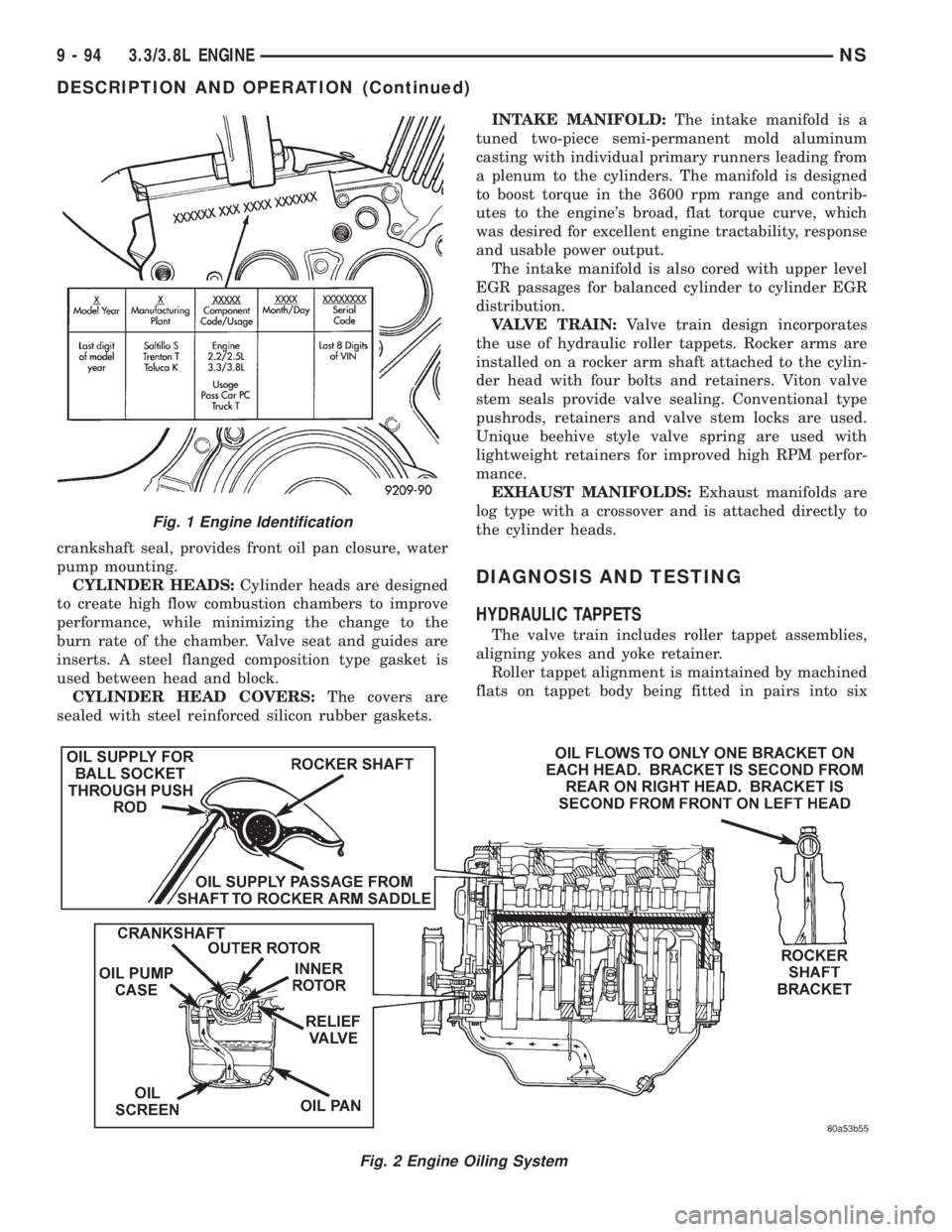
crankshaft seal, provides front oil pan closure, water
pump mounting.
CYLINDER HEADS:Cylinder heads are designed
to create high flow combustion chambers to improve
performance, while minimizing the change to the
burn rate of the chamber. Valve seat and guides are
inserts. A steel flanged composition type gasket is
used between head and block.
CYLINDER HEAD COVERS:The covers are
sealed with steel reinforced silicon rubber gaskets.INTAKE MANIFOLD:The intake manifold is a
tuned two-piece semi-permanent mold aluminum
casting with individual primary runners leading from
a plenum to the cylinders. The manifold is designed
to boost torque in the 3600 rpm range and contrib-
utes to the engine's broad, flat torque curve, which
was desired for excellent engine tractability, response
and usable power output.
The intake manifold is also cored with upper level
EGR passages for balanced cylinder to cylinder EGR
distribution.
VALVE TRAIN:Valve train design incorporates
the use of hydraulic roller tappets. Rocker arms are
installed on a rocker arm shaft attached to the cylin-
der head with four bolts and retainers. Viton valve
stem seals provide valve sealing. Conventional type
pushrods, retainers and valve stem locks are used.
Unique beehive style valve spring are used with
lightweight retainers for improved high RPM perfor-
mance.
EXHAUST MANIFOLDS:Exhaust manifolds are
log type with a crossover and is attached directly to
the cylinder heads.
DIAGNOSIS AND TESTING
HYDRAULIC TAPPETS
The valve train includes roller tappet assemblies,
aligning yokes and yoke retainer.
Roller tappet alignment is maintained by machined
flats on tappet body being fitted in pairs into six
Fig. 2 Engine Oiling System
Fig. 1 Engine Identification
9 - 94 3.3/3.8L ENGINENS
DESCRIPTION AND OPERATION (Continued)