1996 CHRYSLER VOYAGER buttons
[x] Cancel search: buttonsPage 555 of 1938

Removing magnetic interfering objects will usually
restore normal compass operation. If the compass
display remains blank while the CAL label is illumi-
nated, then the roof panel requires demagnetizing. To
demagnetize use Special Tool 6029 for demagnetizing
the roof panel. The demagnetizing procedure will
demagnetize the roof and mounting screws in the
overhead console. It is important that you follow the
instructions below exactly. The mounting screws and
the mounting brackets around the compass area are
steel, and therefore aid in the demagnetizing of the
roof panel.
(1) Be sure the ignition switch is in the OFF posi-
tion before you begin the demagnetize procedure.
(2) Plug the demagnetizing tool into a standard
110/115 volt AC outlet, keeping the demagnetizing
tool at least 12 inches away from the compass area
when plugging it in.
(3) Slowly approach and contact the console
mounting screw with the plastic coated tip of the tool
for at least two seconds.
(4) With the demagnetizing tool still energized,
slowly back it away from the screw until the tip is at
least 12 inches from the screw head.
(5) Repeat the last step with all the console
mounting screws.
(6) After you have pulled at least 12 inches from
the last screw, remove the demagnetizing tool from
inside vehicle and disconnect it from the electrical
outlet.
(7) Place an 8 1/2 X 11 inch piece of paper length-
wise on the roof of vehicle directly above compass.
The purpose of the paper is to protect the roof panel
from scratches and define the area to be demagne-
tized.
(8) Plug in the demagnetizing tool, keeping it at
least two feet away from the compass unit.
(9) Slowly approach the center of the roof panel at
the windshield with the demagnetizing tool plugged
in.
(10) Contact the roof panel with the tip of the tool.
Using slow sweeping motions of 1/2 inch between
sweeps. Move the tool approximately four inches
either side of the center line and at least 11 inches
back from the windshield.
(11) With the demagnetizing tool still energized,
slowly back away from the roof panel until the tip is
at least two feet from the roof before unplugging the
tool.
(12) Recalibrate compass, refer to the compass cal-
ibration procedure in this section.
UNIVERSAL TRANSMITTER
TRAINING
(1) Turn off the engine.(2) Erase the factory test codes by pressing the
two outside buttons. Release the buttons when the
red light begins to flash (about 20 seconds).
(3) Choose one of the three buttons to train. Place
the hand-held transmitter within one inch of the uni-
versal transmitter and push the buttons on both
transmitters. The red light on the universal trans-
mitter will begin to flash slowly.
(4) When the red light on the universal transmit-
ter begins to flash rapidly (this may take as long as
60 seconds), release both buttons. Your universal
transmitter is now ªtrainedº. To train the other but-
tons, repeat Step 3 and Step 4. Be sure to keep your
hand-held transmitter in case you need to retrain the
universal transmitter.
ERASING
To erase the universal transmitter codes, simply
hold down the two outside buttons until the red LED
begins to flash.
NOTE: Individual channels cannot be erased. Eras-
ing the transmitter codes will erase ALL pro-
grammed codes.
REMOVAL AND INSTALLATION
AMBIENT TEMPERATURE SENSOR
REMOVAL
(1) Raise and support vehicle on safety stands.
(2) From behind front bumper fascia, remove
screw holding sensor to radiator closure panel.
(3) Remove sensor from vehicle.
INSTALLATION
For installation, reverse the above procedures.
Fig. 5 Universal Transmitter
NSOVERHEAD CONSOLE 8V - 5
SERVICE PROCEDURES (Continued)
Page 1817 of 1938
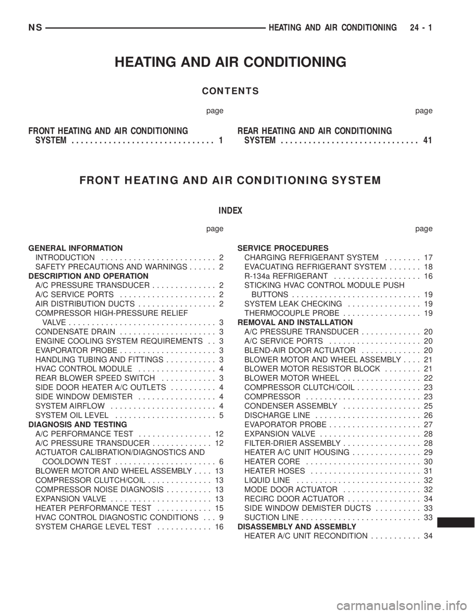
HEATING AND AIR CONDITIONING
CONTENTS
page page
FRONT HEATING AND AIR CONDITIONING
SYSTEM............................... 1REAR HEATING AND AIR CONDITIONING
SYSTEM.............................. 41
FRONT HEATING AND AIR CONDITIONING SYSTEM
INDEX
page page
GENERAL INFORMATION
INTRODUCTION......................... 2
SAFETY PRECAUTIONS AND WARNINGS...... 2
DESCRIPTION AND OPERATION
A/C PRESSURE TRANSDUCER.............. 2
A/C SERVICE PORTS..................... 2
AIR DISTRIBUTION DUCTS................. 2
COMPRESSOR HIGH-PRESSURE RELIEF
VALVE................................ 3
CONDENSATE DRAIN..................... 3
ENGINE COOLING SYSTEM REQUIREMENTS . . 3
EVAPORATOR PROBE..................... 3
HANDLING TUBING AND FITTINGS........... 3
HVAC CONTROL MODULE................. 4
REAR BLOWER SPEED SWITCH............ 3
SIDE DOOR HEATER A/C OUTLETS.......... 4
SIDE WINDOW DEMISTER................. 4
SYSTEM AIRFLOW....................... 4
SYSTEM OIL LEVEL...................... 5
DIAGNOSIS AND TESTING
A/C PERFORMANCE TEST................ 12
A/C PRESSURE TRANSDUCER............. 12
ACTUATOR CALIBRATION/DIAGNOSTICS AND
COOLDOWN TEST...................... 6
BLOWER MOTOR AND WHEEL ASSEMBLY.... 13
COMPRESSOR CLUTCH/COIL.............. 13
COMPRESSOR NOISE DIAGNOSIS.......... 13
EXPANSION VALVE...................... 13
HEATER PERFORMANCE TEST............ 15
HVAC CONTROL DIAGNOSTIC CONDITIONS . . . 9
SYSTEM CHARGE LEVEL TEST............ 16SERVICE PROCEDURES
CHARGING REFRIGERANT SYSTEM........ 17
EVACUATING REFRIGERANT SYSTEM....... 18
R-134a REFRIGERANT................... 16
STICKING HVAC CONTROL MODULE PUSH
BUTTONS............................ 19
SYSTEM LEAK CHECKING................ 19
THERMOCOUPLE PROBE................. 19
REMOVAL AND INSTALLATION
A/C PRESSURE TRANSDUCER............. 20
A/C SERVICE PORTS.................... 20
BLEND-AIR DOOR ACTUATOR............. 20
BLOWER MOTOR AND WHEEL ASSEMBLY.... 21
BLOWER MOTOR RESISTOR BLOCK........ 21
BLOWER MOTOR WHEEL................. 22
COMPRESSOR CLUTCH/COIL.............. 23
COMPRESSOR......................... 23
CONDENSER ASSEMBLY................. 25
DISCHARGE LINE....................... 26
EVAPORATOR PROBE.................... 27
EXPANSION VALVE...................... 28
FILTER-DRIER ASSEMBLY................. 28
HEATER A/C UNIT HOUSING............... 29
HEATER CORE......................... 30
HEATER HOSES........................ 31
LIQUID LINE........................... 32
MODE DOOR ACTUATOR................. 32
RECIRC DOOR ACTUATOR................ 34
SIDE WINDOW DEMISTER DUCTS.......... 33
SUCTION LINE.......................... 33
DISASSEMBLY AND ASSEMBLY
HEATER A/C UNIT RECONDITION........... 34
NSHEATING AND AIR CONDITIONING 24 - 1
Page 1824 of 1938
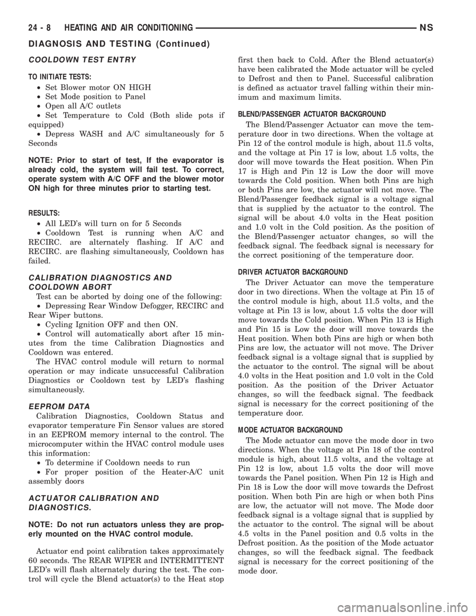
COOLDOWN TEST ENTRY
TO INITIATE TESTS:
²Set Blower motor ON HIGH
²Set Mode position to Panel
²Open all A/C outlets
²Set Temperature to Cold (Both slide pots if
equipped)
²Depress WASH and A/C simultaneously for 5
Seconds
NOTE: Prior to start of test, If the evaporator is
already cold, the system will fail test. To correct,
operate system with A/C OFF and the blower motor
ON high for three minutes prior to starting test.
RESULTS:
²All LED's will turn on for 5 Seconds
²Cooldown Test is running when A/C and
RECIRC. are alternately flashing. If A/C and
RECIRC. are flashing simultaneously, Cooldown has
failed.
CALIBRATION DIAGNOSTICS AND
COOLDOWN ABORT
Test can be aborted by doing one of the following:
²Depressing Rear Window Defogger, RECIRC and
Rear Wiper buttons.
²Cycling Ignition OFF and then ON.
²Control will automatically abort after 15 min-
utes from the time Calibration Diagnostics and
Cooldown was entered.
The HVAC control module will return to normal
operation or may indicate unsuccessful Calibration
Diagnostics or Cooldown test by LED's flashing
simultaneously.
EEPROM DATA
Calibration Diagnostics, Cooldown Status and
evaporator temperature Fin Sensor values are stored
in an EEPROM memory internal to the control. The
microcomputer within the HVAC control module uses
this information:
²To determine if Cooldown needs to run
²For proper position of the Heater-A/C unit
assembly doors
ACTUATOR CALIBRATION AND
DIAGNOSTICS.
NOTE: Do not run actuators unless they are prop-
erly mounted on the HVAC control module.
Actuator end point calibration takes approximately
60 seconds. The REAR WIPER and INTERMITTENT
LED's will flash alternately during the test. The con-
trol will cycle the Blend actuator(s) to the Heat stopfirst then back to Cold. After the Blend actuator(s)
have been calibrated the Mode actuator will be cycled
to Defrost and then to Panel. Successful calibration
is defined as actuator travel falling within their min-
imum and maximum limits.
BLEND/PASSENGER ACTUATOR BACKGROUND
The Blend/Passenger Actuator can move the tem-
perature door in two directions. When the voltage at
Pin 12 of the control module is high, about 11.5 volts,
and the voltage at Pin 17 is low, about 1.5 volts, the
door will move towards the Heat position. When Pin
17 is High and Pin 12 is Low the door will move
towards the Cold position. When both Pins are high
or both Pins are low, the actuator will not move. The
Blend/Passenger feedback signal is a voltage signal
that is supplied by the actuator to the control. The
signal will be about 4.0 volts in the Heat position
and 1.0 volt in the Cold position. As the position of
the Blend/Passenger actuator changes, so will the
feedback signal. The feedback signal is necessary for
the correct positioning of the temperature door.
DRIVER ACTUATOR BACKGROUND
The Driver Actuator can move the temperature
door in two directions. When the voltage at Pin 15 of
the control module is high, about 11.5 volts, and the
voltage at Pin 13 is low, about 1.5 volts the door will
move towards the Cold position. When Pin 13 is High
and Pin 15 is Low the door will move towards the
Heat position. When both Pins are high or when both
Pins are low, the actuator will not move. The Driver
feedback signal is a voltage signal that is supplied by
the actuator to the control. The signal will be about
4.0 volts in the Heat position and 1.0 volt in the Cold
position. As the position of the Driver Actuator
changes, so will the feedback signal. The feedback
signal is necessary for the correct positioning of the
temperature door.
MODE ACTUATOR BACKGROUND
The Mode actuator can move the mode door in two
directions. When the voltage at Pin 18 of the control
module is high, about 11.5 volts, and the voltage at
Pin 12 is low, about 1.5 volts the door will move
towards the Panel position. When Pin 12 is High and
Pin 18 is Low the door will move towards the Defrost
position. When both Pin are high or when both Pins
are low, the actuator will not move. The Mode door
feedback signal is a voltage signal that is supplied by
the actuator to the control. The signal will be about
4.5 volts in the Panel position and 0.5 volts in the
Defrost position. As the position of the Mode actuator
changes, so will the feedback signal. The feedback
signal is necessary for the correct positioning of the
mode door.
24 - 8 HEATING AND AIR CONDITIONINGNS
DIAGNOSIS AND TESTING (Continued)
Page 1835 of 1938
eliminate all moisture in system. When the suction
gauge reads -88 kPa (- 26 in. Hg) vacuum or greater
for 45 minutes, close all valves and turn off vacuum
pump. If the system fails to reach specified vacuum,
the refrigerant system likely has a leak that must be
corrected. If the refrigerant system maintains speci-
fied vacuum for at least 30 minutes, start the vac-
uum pump, open the suction and discharge valves.
Then allow the system to evacuate an additional 10
minutes.
(3) Close all valves. Turn off and disconnect the
vacuum pump.
(4) The refrigerant system is prepared to be
charged with refrigerant.
THERMOCOUPLE PROBE
To diagnose the A/C system, a temperature probe is
required to measure liquid line temperature. The
clamp-on type K probe shown in this manual is avail-
able through the Chrysler Professional Service
Equipment (PSE) program. This probe is compatible
with temperature-measuring instruments that accept
Type K Thermocouples and have a miniature connec-
tor input. Other temperature probes are available
through aftermarket sources. All references in this
manual will reflect the use of the probe made avail-
able through the Professional Service Equipment pro-
gram.
In order to use the temperature probe, a digital
thermometer will be required. If a digital thermome-
ter is not available, an adapter is available through
the Professional Service Equipment program. It can
convert any standard digital multimeter into a ther-
mometer. This adapter is designed to accept any
standard K-type thermocouple.
If a digital multimeter is not available, it to can be
ordered through Professional Service Equipment pro-
gram.
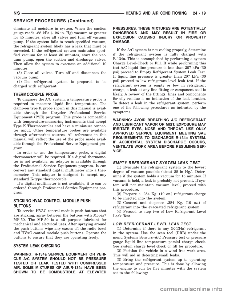
STICKING HVAC CONTROL MODULE PUSH
BUTTONS
To service HVAC control module push buttons that
are sticking, spray between the buttons with Mopart
MP-50. The MP-50 is a all purpose lubricant for
mechanical and electrical uses. After spraying around
the push buttons wipe any excess off the radio bezel
and HVAC control module push buttons. Operate the
buttons to ensure that they are operating freely.
SYSTEM LEAK CHECKING
WARNING: R-134a SERVICE EQUIPMENT OR VEHI-
CLE A/C SYSTEM SHOULD NOT BE PRESSURE
TESTED OR LEAK TESTED WITH COMPRESSED
AIR. SOME MIXTURES OF AIR/R-134a HAVE BEEN
SHOWN TO BE COMBUSTIBLE AT ELEVATEDPRESSURES. THESE MIXTURES ARE POTENTIALLY
DANGEROUS AND MAY RESULT IN FIRE OR
EXPLOSION CAUSING INJURY OR PROPERTY
DAMAGE.
If the A/C system is not cooling properly, determine
if the refrigerant system is fully charged with
R-134a. This is accomplished by performing a system
Charge Level-Check or Fill. If while performing this
test A/C liquid line pressure is less than 207 kPa (30
psi) proceed to Empty Refrigerant System Leak Test.
If liquid line pressure is greater than 207 kPa (30
psi) proceed to low refrigerant level leak test. If the
refrigerant system is empty or low in refrigerant
charge, a leak at any line fitting or component seal is
likely. A review of the fittings, lines and components
for oily residue is an indication of the leak location.
To detect a leak in the refrigerant system, perform
one of the following procedures as indicated by the
symptoms.
WARNING: AVOID BREATHING A/C REFRIGERANT
AND LUBRICANT VAPOR OR MIST. EXPOSURE MAY
IRRITATE EYES, NOSE AND THROAT. USE ONLY
APPROVED SERVICE EQUIPMENT MEETING SAE
REQUIREMENTS TO DISCHARGE R-134a SYSTEM.
IF ACCIDENTAL SYSTEM DISCHARGE OCCURS,
VENTILATE WORK AREA BEFORE RESUMING SER-
VICE.
EMPTY REFRIGERANT SYSTEM LEAK TEST
(1) Evacuate the refrigerant system to the lowest
degree of vacuum possible (about 28 in Hg.). Deter-
mine if the system holds a vacuum for 15 minutes. If
vacuum is held, a leak is probably not present. If sys-
tem will not maintain vacuum level, proceed with
this procedure.
(2) Prepare a .284 Kg. (10 oz.) refrigerant charge
to be injected into the system.
(3) Connect and dispense .284 Kg. (10 oz.) of
refrigerant into the evacuated refrigerant system.
(4) Proceed to step two of Low Refrigerant Level
Leak Test.
LOW REFRIGERANT LEVEL LEAK TEST
(1) Determine if there is any (R-134a) refrigerant
in the system. Use the scan tool (DRB) under the
menu Systems Sensors±A/C Pressure test or pressure
gauge liquid line temperature partial charge check.
See system charge level check or fill for procedure.
(2) Position the vehicle in a wind free work area.
This will aid in detecting small leaks.
(3) Bring the refrigerant system up to operating
temperature and pressure. This is done by allowing
the engine to run for five minutes with the system
set to the following:
NSHEATING AND AIR CONDITIONING 24 - 19
SERVICE PROCEDURES (Continued)
Page 1867 of 1938
HEATING AND AIR CONDITIONING
CONTENTS
page page
GENERAL INFORMATION
INTRODUCTION........................ 1
SAFETY PRECAUTIONS AND WARNINGS.... 2
DESCRIPTION AND OPERATION
A/C PRESSURE TRANSDUCER............ 2
A/C SERVICE PORTS.................... 2
AIR DISTRIBUTION DUCTS............... 2
COMPRESSOR......................... 2
COMPRESSOR HIGH-PRESSURE RELIEF
VALVE .............................. 3
CONDENSATE DRAIN.................... 3
ENGINE COOLING SYSTEM REQUIREMENTS . 3
EVAPORATOR PROBE................... 3
HANDLING TUBING AND FITTINGS........ 3
HVAC CONTROL MODULE................ 3
SIDE DOOR HEATER A/C OUTLETS........ 4
SIDE WINDOW DEMISTER............... 4
SYSTEM AIRFLOW..................... 4
SYSTEM OIL LEVEL..................... 4
DIAGNOSIS AND TESTING
A/C PERFORMANCE TEST............... 11
A/C PRESSURE TRANSDUCER........... 11
ACTUATOR CALIBRATION/DIAGNOSTICS AND
COOLDOWN TEST..................... 5
BLOWER MOTOR AND WHEEL ASSEMBLY . 12
COMPRESSOR CLUTCH/COIL............ 12
COMPRESSOR NOISE DIAGNOSIS........ 12
EXPANSION VALVE.................... 14
HEATER PERFORMANCE TEST........... 14
HVAC CONTROL DIAGNOSTIC CONDITIONS . 9
SYSTEM CHARGE LEVEL TEST........... 15SERVICE PROCEDURES
CHARGING REFRIGERANT SYSTEM....... 17
EVACUATING REFRIGERANT SYSTEM..... 17
R-134a REFRIGERANT.................. 16
STICKING HVAC CONTROL MODULE PUSH
BUTTONS.......................... 18
SYSTEM LEAK CHECKING............... 19
THERMOCOUPLE PROBE............... 18
REMOVAL AND INSTALLATION
A/C PRESSURE TRANSDUCER........... 19
A/C SERVICE PORTS................... 19
BLEND-AIR DOOR ACTUATOR........... 20
BLOWER MOTOR AND WHEEL ASSEMBLY . 20
BLOWER MOTOR RESISTOR BLOCK...... 21
BLOWER MOTOR WHEEL............... 22
COMPRESSOR (2.5L TURBO DIESEL)..... 22
CONDENSER ASSEMBLY................ 23
DISCHARGE LINE..................... 23
EVAPORATOR PROBE.................. 24
EXPANSION VALVE.................... 25
FILTER-DRIER ASSEMBLY............... 26
HEATER A/C UNIT HOUSING............. 26
HEATER CORE........................ 26
HEATER HOSES....................... 28
LIQUID LINE......................... 28
MODE DOOR ACTUATOR................ 29
RECIRC DOOR ACTUATOR.............. 30
SIDE WINDOW DEMISTER DUCTS........ 29
SUCTION LINE........................ 29
DISASSEMBLY AND ASSEMBLY
HEATER A/C UNIT RECONDITION......... 30
GENERAL INFORMATION
INTRODUCTION
The Heater, or Heater and Air Conditioning sys-
tems share many of the same components. This
group will deal with both systems together when
component function is common, and separately when
they are not.
For proper operation of the instrument panel con-
trols, refer to the Owner's Manual provided with the
vehicle.All vehicles are equipped with a common Heater
A/C unit housing assembly. When the vehicle has
only a heater system, the evaporator and recirculat-
ing air door are omitted.
An optional zone control HVAC unit is available.
This unit has dual blend-air doors that can be regu-
lated independently of each other. The temperature
setting can be different from driver's side to passen-
ger side.
NS/GSHEATING AND AIR CONDITIONING 24 - 1
Page 1873 of 1938
COOLDOWN TEST ENTRY
TO INITIATE TESTS:
²Set Blower motor ON HIGH
²Set Mode position to Panel
²Open all A/C outlets
²Set Temperature to Cold (Both slide pots if
equipped)
²Depress WASH and A/C simultaneously for 5
Seconds
NOTE: Prior to start of test, If the evaporator is
already cold, the system will fail test. To correct,
operate system with A/C OFF and the blower motor
ON high for three minutes prior to starting test.
RESULTS:
²All LED's will turn on for 5 Seconds
²Cooldown Test is running when A/C and
RECIRC. are alternately flashing. If A/C and
RECIRC. are flashing simultaneously, Cooldown has
failed.
CALIBRATION DIAGNOSTICS AND
COOLDOWN ABORT
Test can be aborted by doing one of the following:
²Depressing Rear Window Defogger, RECIRC and
Rear Wiper buttons.²Cycling Ignition OFF and then ON.
²Control will automatically abort after 15 min-
utes from the time Calibration Diagnostics and
Cooldown was entered.
The HVAC control module will return to normal
operation or may indicate unsuccessful Calibration
Diagnostics or Cooldown test by LED's flashing
simultaneously.
EEPROM DATA
Calibration Diagnostics, Cooldown Status and
evaporator temperature Fin Sensor values are stored
in an EEPROM memory internal to the control. The
microcomputer within the HVAC control module uses
this information:
²To determine if Cooldown needs to run
²For proper position of the Heater-A/C unit
assembly doors
ACTUATOR CALIBRATION AND
DIAGNOSTICS.
NOTE: Do not run actuators unless they are prop-
erly mounted on the HVAC control module.
Actuator end point calibration takes approximately
60 seconds. The REAR WIPER and INTERMITTENT
LED's will flash alternately during the test. The con-
trol will cycle the Blend actuator(s) to the Heat stop
first then back to Cold. After the Blend actuator(s)
have been calibrated the Mode actuator will be cycled
to Defrost and then to Panel. Successful calibration
is defined as actuator travel falling within their min-
imum and maximum limits.
BLEND/PASSENGER ACTUATOR BACKGROUND
The Blend/Passenger Actuator can move the tem-
perature door in two directions. When the voltage at
Pin 12 of the control module is high, about 11.5 volts,
and the voltage at Pin 17 is low, about 1.5 volts, the
door will move towards the Heat position. When Pin
17 is High and Pin 12 is Low the door will move
towards the Cold position. When both Pins are high
or both Pins are low, the actuator will not move. The
Blend/Passenger feedback signal is a voltage signal
that is supplied by the actuator to the control. The
signal will be about 4.0 volts in the Heat position
and 1.0 volt in the Cold position. As the position of
the Blend/Passenger actuator changes, so will the
feedback signal. The feedback signal is necessary for
the correct positioning of the temperature door.
DRIVER ACTUATOR BACKGROUND
The Driver Actuator can move the temperature
door in two directions. When the voltage at Pin 15 of
the control module is high, about 11.5 volts, and the
voltage at Pin 13 is low, about 1.5 volts the door will
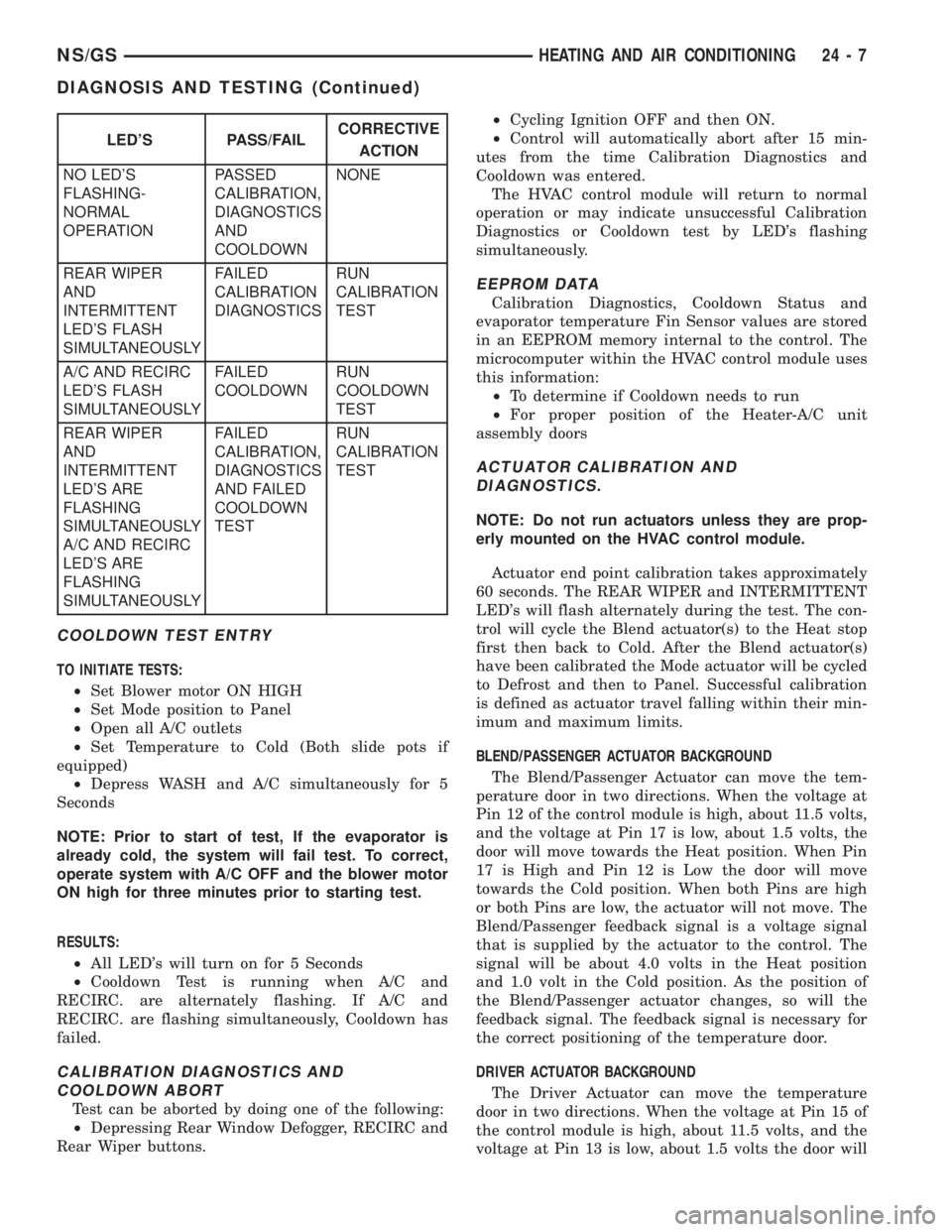
LED'S PASS/FAILCORRECTIVE
ACTION
NO LED'S
FLASHING-
NORMAL
OPERATIONPASSED
CALIBRATION,
DIAGNOSTICS
AND
COOLDOWNNONE
REAR WIPER
AND
INTERMITTENT
LED'S FLASH
SIMULTANEOUSLYFAILED
CALIBRATION
DIAGNOSTICSRUN
CALIBRATION
TEST
A/C AND RECIRC
LED'S FLASH
SIMULTANEOUSLYFAILED
COOLDOWNRUN
COOLDOWN
TEST
REAR WIPER
AND
INTERMITTENT
LED'S ARE
FLASHING
SIMULTANEOUSLY
A/C AND RECIRC
LED'S ARE
FLASHING
SIMULTANEOUSLYFAILED
CALIBRATION,
DIAGNOSTICS
AND FAILED
COOLDOWN
TESTRUN
CALIBRATION
TEST
NS/GSHEATING AND AIR CONDITIONING 24 - 7
DIAGNOSIS AND TESTING (Continued)
Page 1884 of 1938
(3) Close all valves. Turn off and disconnect the
vacuum pump.
(4) The refrigerant system is prepared to be
charged with refrigerant.
THERMOCOUPLE PROBE
To diagnose the A/C system, a temperature probe is
required to measure liquid line temperature. The
clamp-on type K probe shown in this manual is avail-
able through the Chrysler Professional Service Equip-
ment (PSE) program. This probe is compatible with
temperature-measuring instruments that accept Type
K Thermocouples and have a miniature connector
input. Other temperature probes are available through
aftermarket sources. All references in this manual will
reflect the use of the probe made available through the
Professional Service Equipment program.
In order to use the temperature probe, a digital
thermometer will be required. If a digital thermo-meter is not available, an adapter is available
through the Professional Service Equipment pro-
gram. It can convert any standard digital multimeter
into a thermometer. This adapter is designed to
accept any standard K-type thermocouple.
If a digital multimeter is not available, it to can be
ordered through Professional Service Equipment pro-
gram.
STICKING HVAC CONTROL MODULE PUSH
BUTTONS
To service HVAC control module push buttons that
are sticking, spray between the buttons with Mopart
MP-50. The MP-50 is a all purpose lubricant for
mechanical and electrical uses. After spraying around
the push buttons wipe any excess off the radio bezel
and HVAC control module push buttons. Operate the
buttons to ensure that they are operating freely.
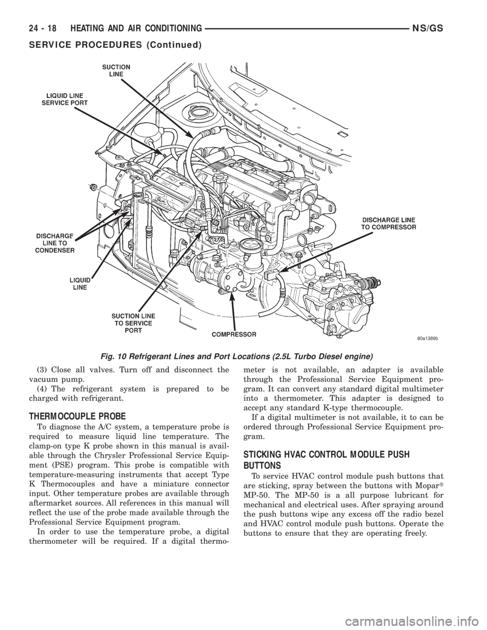
Fig. 10 Refrigerant Lines and Port Locations (2.5L Turbo Diesel engine)
24 - 18 HEATING AND AIR CONDITIONINGNS/GS
SERVICE PROCEDURES (Continued)