Page 212 of 1938

friction area should be slightly concave, with the
inner diameter 0.02 mm to 0.1 mm (.0008 in. to .0039
in.) below the outer diameter. It should also be free
from discoloration, burned areas, cracks, grooves, or
ridges.
Using a surface plate, test cover for flatness. All
sections around attaching bolt holes should be in con-
tact with surface plate within .015 inch.
The cover should be a snug fit on flywheel dowels.
If the clutch assembly does not meet these require-
ments, it should be replaced.
INSTALLATION
(1) Position the clutch and pressure plate onto the
flywheel.
(2) Insert the universal clutch alignment tool into
the clutch disc.
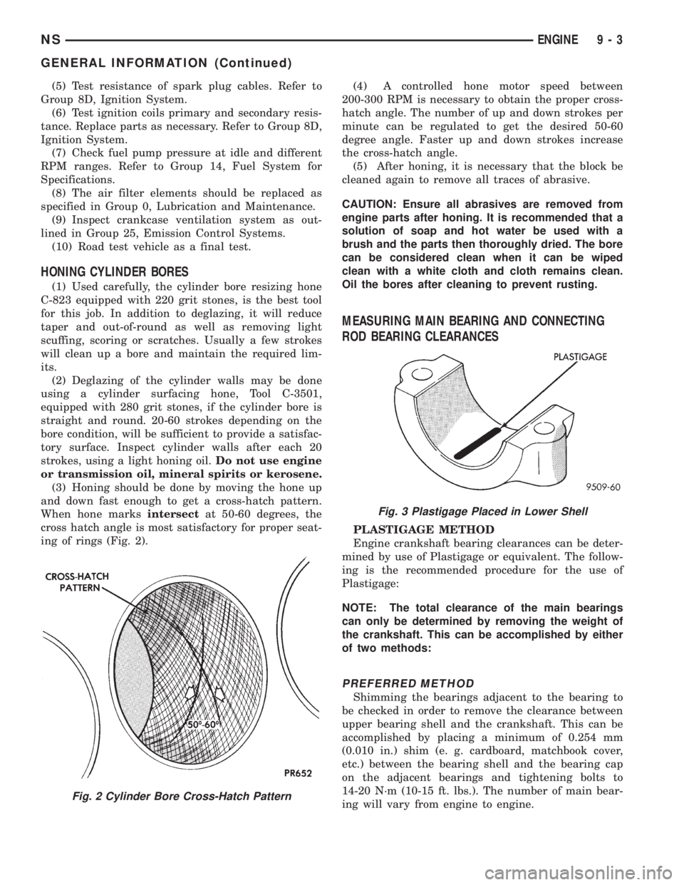
(3) To avoid distortion of the pressure plate, bolts
should be tightened a few turns at a time (Fig. 19).
Use a crisscross pattern until all bolts are seated.
Tighten pressure plate bolts to 27 N´m (20 ft. lbs.).
(4) Remove the universal clutch alignment tool.
(5) Install the transaxle, refer to Group 21, Tran-
saxle.
(6) Fill transaxle to the proper level with the spec-
ified lubricant.
(7) While the vehicle is elevated slightly, run the
transaxle through all the forward gears. Apply
brakes and shift into reverse. Run the transaxle
through reverse gear.
(8) Check the transaxle for leaks and recheck the
level of the transaxle lubricant.
CLUTCH RELEASE BEARING AND FORK
Remove the transaxle from the vehicle. See Group
21, for removal and installation procedures.
REMOVAL
(1) Remove clutch release shaft E-clip (Fig. 20).
(2) Remove the clutch release shaft and then slide
the fork and bearing assembly off the bearing pilot
(Fig. 21).
Fig. 19 2.5 Diesel Clutch Assembly
Fig. 20 E-clip at Clutch Release Lever Shaft
Fig. 21 Clutch Release Shaft
6 - 14 CLUTCHNS/GS
REMOVAL AND INSTALLATION (Continued)
Page 1053 of 1938

(5) Test resistance of spark plug cables. Refer to
Group 8D, Ignition System.
(6) Test ignition coils primary and secondary resis-
tance. Replace parts as necessary. Refer to Group 8D,
Ignition System.
(7) Check fuel pump pressure at idle and different
RPM ranges. Refer to Group 14, Fuel System for
Specifications.
(8) The air filter elements should be replaced as
specified in Group 0, Lubrication and Maintenance.
(9) Inspect crankcase ventilation system as out-
lined in Group 25, Emission Control Systems.
(10) Road test vehicle as a final test.
HONING CYLINDER BORES
(1) Used carefully, the cylinder bore resizing hone
C-823 equipped with 220 grit stones, is the best tool
for this job. In addition to deglazing, it will reduce
taper and out-of-round as well as removing light
scuffing, scoring or scratches. Usually a few strokes
will clean up a bore and maintain the required lim-
its.
(2) Deglazing of the cylinder walls may be done
using a cylinder surfacing hone, Tool C-3501,
equipped with 280 grit stones, if the cylinder bore is
straight and round. 20-60 strokes depending on the
bore condition, will be sufficient to provide a satisfac-
tory surface. Inspect cylinder walls after each 20
strokes, using a light honing oil.Do not use engine
or transmission oil, mineral spirits or kerosene.
(3) Honing should be done by moving the hone up
and down fast enough to get a cross-hatch pattern.
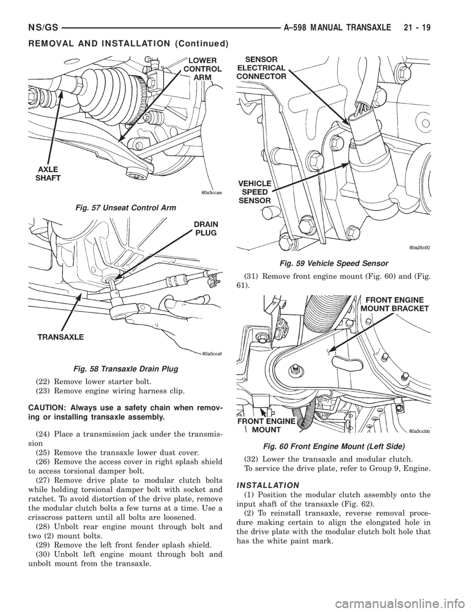
When hone marksintersectat 50-60 degrees, the
cross hatch angle is most satisfactory for proper seat-
ing of rings (Fig. 2).(4) A controlled hone motor speed between
200-300 RPM is necessary to obtain the proper cross-
hatch angle. The number of up and down strokes per
minute can be regulated to get the desired 50-60
degree angle. Faster up and down strokes increase
the cross-hatch angle.
(5) After honing, it is necessary that the block be
cleaned again to remove all traces of abrasive.
CAUTION: Ensure all abrasives are removed from
engine parts after honing. It is recommended that a
solution of soap and hot water be used with a
brush and the parts then thoroughly dried. The bore
can be considered clean when it can be wiped
clean with a white cloth and cloth remains clean.
Oil the bores after cleaning to prevent rusting.
MEASURING MAIN BEARING AND CONNECTING
ROD BEARING CLEARANCES
PLASTIGAGE METHOD
Engine crankshaft bearing clearances can be deter-
mined by use of Plastigage or equivalent. The follow-
ing is the recommended procedure for the use of
Plastigage:
NOTE: The total clearance of the main bearings
can only be determined by removing the weight of
the crankshaft. This can be accomplished by either
of two methods:
PREFERRED METHOD
Shimming the bearings adjacent to the bearing to
be checked in order to remove the clearance between
upper bearing shell and the crankshaft. This can be
accomplished by placing a minimum of 0.254 mm
(0.010 in.) shim (e. g. cardboard, matchbook cover,
etc.) between the bearing shell and the bearing cap
on the adjacent bearings and tightening bolts to
14-20 N´m (10-15 ft. lbs.). The number of main bear-
ing will vary from engine to engine.
Fig. 2 Cylinder Bore Cross-Hatch Pattern
Fig. 3 Plastigage Placed in Lower Shell
NSENGINE 9 - 3
GENERAL INFORMATION (Continued)
Page 1675 of 1938

(22) Remove lower starter bolt.
(23) Remove engine wiring harness clip.
CAUTION: Always use a safety chain when remov-
ing or installing transaxle assembly.
(24) Place a transmission jack under the transmis-
sion
(25) Remove the transaxle lower dust cover.
(26) Remove the access cover in right splash shield
to access torsional damper bolt.
(27) Remove drive plate to modular clutch bolts
while holding torsional damper bolt with socket and
ratchet. To avoid distortion of the drive plate, remove
the modular clutch bolts a few turns at a time. Use a
crisscross pattern until all bolts are loosened.
(28) Unbolt rear engine mount through bolt and
two (2) mount bolts.
(29) Remove the left front fender splash shield.
(30) Unbolt left engine mount through bolt and
unbolt mount from the transaxle.(31) Remove front engine mount (Fig. 60) and (Fig.
61).
(32) Lower the transaxle and modular clutch.
To service the drive plate, refer to Group 9, Engine.
INSTALLATION
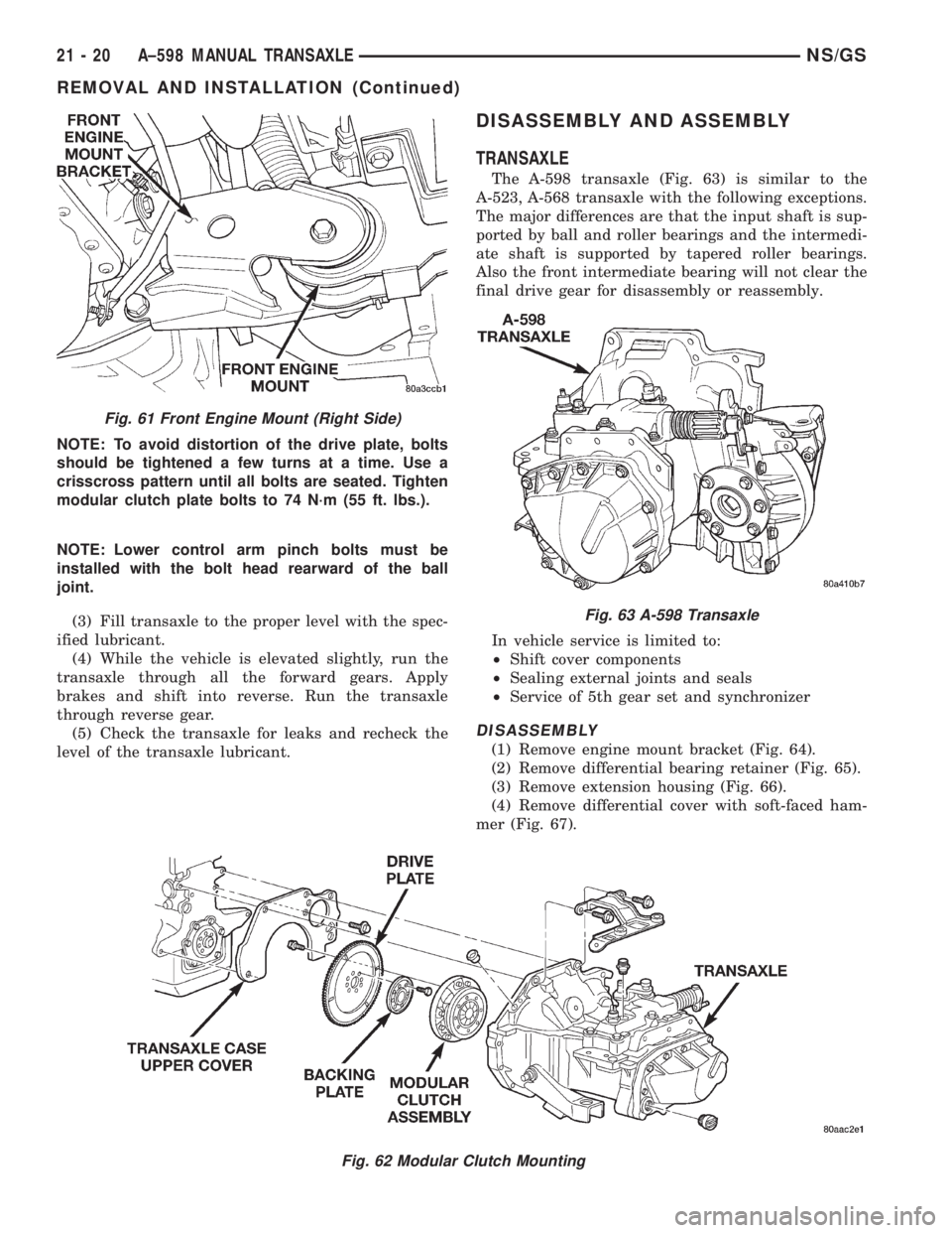
(1) Position the modular clutch assembly onto the
input shaft of the transaxle (Fig. 62).
(2) To reinstall transaxle, reverse removal proce-
dure making certain to align the elongated hole in
the drive plate with the modular clutch bolt hole that
has the white paint mark.
Fig. 57 Unseat Control Arm
Fig. 58 Transaxle Drain Plug
Fig. 59 Vehicle Speed Sensor
Fig. 60 Front Engine Mount (Left Side)
NS/GSA±598 MANUAL TRANSAXLE 21 - 19
REMOVAL AND INSTALLATION (Continued)
Page 1676 of 1938

NOTE: To avoid distortion of the drive plate, bolts
should be tightened a few turns at a time. Use a
crisscross pattern until all bolts are seated. Tighten
modular clutch plate bolts to 74 N´m (55 ft. lbs.).
NOTE: Lower control arm pinch bolts must be
installed with the bolt head rearward of the ball
joint.
(3) Fill transaxle to the proper level with the spec-
ified lubricant.
(4) While the vehicle is elevated slightly, run the
transaxle through all the forward gears. Apply
brakes and shift into reverse. Run the transaxle
through reverse gear.
(5) Check the transaxle for leaks and recheck the
level of the transaxle lubricant.
DISASSEMBLY AND ASSEMBLY
TRANSAXLE
The A-598 transaxle (Fig. 63) is similar to the
A-523, A-568 transaxle with the following exceptions.
The major differences are that the input shaft is sup-
ported by ball and roller bearings and the intermedi-
ate shaft is supported by tapered roller bearings.
Also the front intermediate bearing will not clear the
final drive gear for disassembly or reassembly.
In vehicle service is limited to:
²Shift cover components
²Sealing external joints and seals
²Service of 5th gear set and synchronizer
DISASSEMBLY
(1) Remove engine mount bracket (Fig. 64).
(2) Remove differential bearing retainer (Fig. 65).
(3) Remove extension housing (Fig. 66).
(4) Remove differential cover with soft-faced ham-
mer (Fig. 67).
Fig. 62 Modular Clutch Mounting
Fig. 61 Front Engine Mount (Right Side)
Fig. 63 A-598 Transaxle
21 - 20 A±598 MANUAL TRANSAXLENS/GS
REMOVAL AND INSTALLATION (Continued)