1996 CHRYSLER VOYAGER check oil
[x] Cancel search: check oilPage 1250 of 1938
(4) Face chamber recess side of piston towards
camshaft.
(5) Install connecting rod bolt protectors on rod
bolts.
(6) Rotate crankshaft so that the connecting rod
journal is on the center of the cylinder bore. Insert
rod and piston into cylinder bore and guide rod over
the crankshaft journal.
CAUTION: During piston and rod installation. DO
NOT rotate piston and connecting rod or damage to
the oil jets extending out into the cylinder bore will
occur (Fig. 56).
(7) Tap the piston down in cylinder bore, using a
hammer handle. At the same time, guide connecting
rod into position on connecting rod journal.
(8) Install rod caps. Install nuts on cleaned and
oiled rod bolts and tighten nuts to 29.5 N´m (22 ft.
lb.) plus 60É.
CYLINDER LINER
REMOVAL
(1) Remove cylinder heads (refer to cylinder head
removal in this section).
(2) Remove Oil pan (refer to oil pan removal in
this section).
(3) Remove pistons (refer to piston removal in this
section).
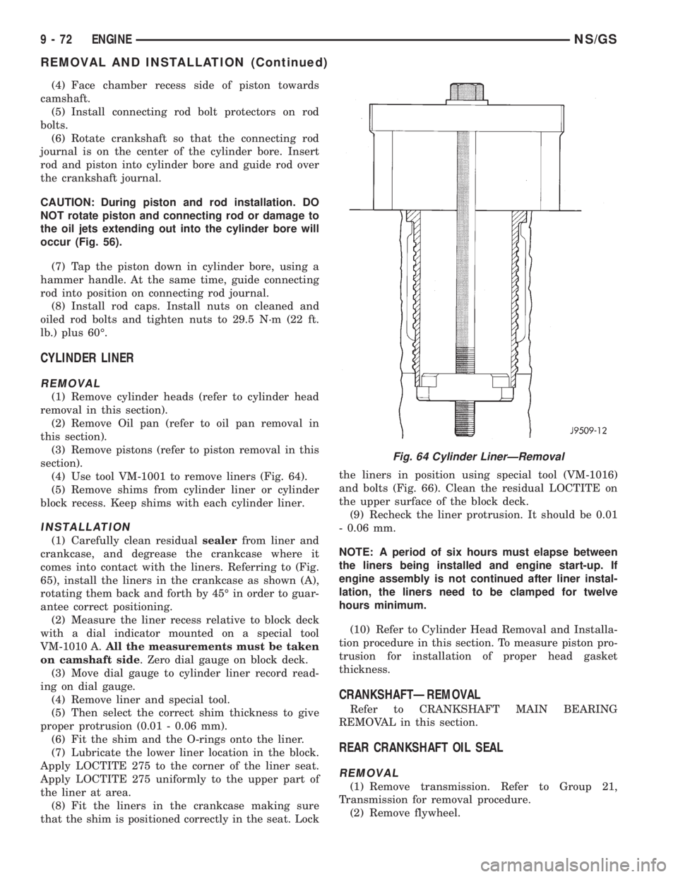
(4) Use tool VM-1001 to remove liners (Fig. 64).
(5) Remove shims from cylinder liner or cylinder
block recess. Keep shims with each cylinder liner.
INSTALLATION
(1) Carefully clean residualsealerfrom liner and
crankcase, and degrease the crankcase where it
comes into contact with the liners. Referring to (Fig.
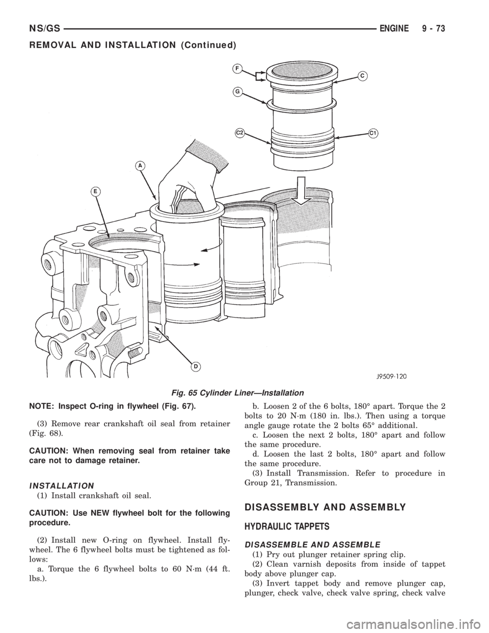
65), install the liners in the crankcase as shown (A),
rotating them back and forth by 45É in order to guar-
antee correct positioning.
(2) Measure the liner recess relative to block deck
with a dial indicator mounted on a special tool
VM-1010 A.All the measurements must be taken
on camshaft side. Zero dial gauge on block deck.
(3) Move dial gauge to cylinder liner record read-
ing on dial gauge.
(4) Remove liner and special tool.
(5) Then select the correct shim thickness to give
proper protrusion (0.01 - 0.06 mm).
(6) Fit the shim and the O-rings onto the liner.
(7) Lubricate the lower liner location in the block.
Apply LOCTITE 275 to the corner of the liner seat.
Apply LOCTITE 275 uniformly to the upper part of
the liner at area.
(8) Fit the liners in the crankcase making sure
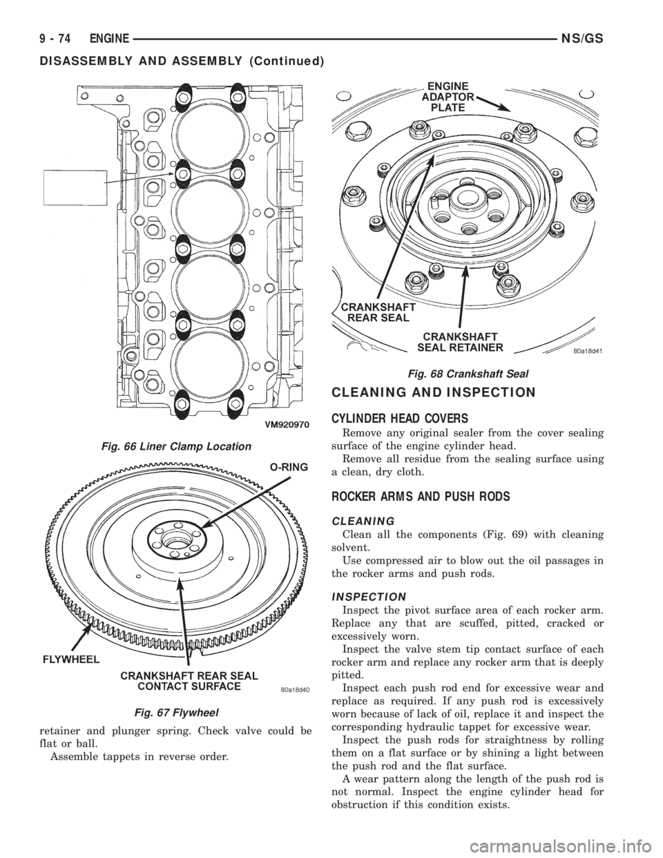
that the shim is positioned correctly in the seat. Lockthe liners in position using special tool (VM-1016)
and bolts (Fig. 66). Clean the residual LOCTITE on
the upper surface of the block deck.
(9) Recheck the liner protrusion. It should be 0.01
- 0.06 mm.
NOTE: A period of six hours must elapse between
the liners being installed and engine start-up. If
engine assembly is not continued after liner instal-
lation, the liners need to be clamped for twelve
hours minimum.
(10) Refer to Cylinder Head Removal and Installa-
tion procedure in this section. To measure piston pro-
trusion for installation of proper head gasket
thickness.
CRANKSHAFTÐREMOVAL
Refer to CRANKSHAFT MAIN BEARING
REMOVAL in this section.
REAR CRANKSHAFT OIL SEAL
REMOVAL
(1) Remove transmission. Refer to Group 21,
Transmission for removal procedure.
(2) Remove flywheel.
Fig. 64 Cylinder LinerÐRemoval
9 - 72 ENGINENS/GS
REMOVAL AND INSTALLATION (Continued)
Page 1251 of 1938
NOTE: Inspect O-ring in flywheel (Fig. 67).
(3) Remove rear crankshaft oil seal from retainer
(Fig. 68).
CAUTION: When removing seal from retainer take
care not to damage retainer.
INSTALLATION
(1) Install crankshaft oil seal.
CAUTION: Use NEW flywheel bolt for the following
procedure.
(2) Install new O-ring on flywheel. Install fly-
wheel. The 6 flywheel bolts must be tightened as fol-
lows:
a. Torque the 6 flywheel bolts to 60 N´m (44 ft.
lbs.).b. Loosen 2 of the 6 bolts, 180É apart. Torque the 2
bolts to 20 N´m (180 in. lbs.). Then using a torque
angle gauge rotate the 2 bolts 65É additional.
c. Loosen the next 2 bolts, 180É apart and follow
the same procedure.
d. Loosen the last 2 bolts, 180É apart and follow
the same procedure.
(3) Install Transmission. Refer to procedure in
Group 21, Transmission.
DISASSEMBLY AND ASSEMBLY
HYDRAULIC TAPPETS
DISASSEMBLE AND ASSEMBLE
(1) Pry out plunger retainer spring clip.
(2) Clean varnish deposits from inside of tappet
body above plunger cap.
(3) Invert tappet body and remove plunger cap,
plunger, check valve, check valve spring, check valve
Fig. 65 Cylinder LinerÐInstallation
NS/GSENGINE 9 - 73
REMOVAL AND INSTALLATION (Continued)
Page 1252 of 1938
retainer and plunger spring. Check valve could be
flat or ball.
Assemble tappets in reverse order.
CLEANING AND INSPECTION
CYLINDER HEAD COVERS
Remove any original sealer from the cover sealing
surface of the engine cylinder head.
Remove all residue from the sealing surface using
a clean, dry cloth.
ROCKER ARMS AND PUSH RODS
CLEANING
Clean all the components (Fig. 69) with cleaning
solvent.
Use compressed air to blow out the oil passages in
the rocker arms and push rods.
INSPECTION
Inspect the pivot surface area of each rocker arm.
Replace any that are scuffed, pitted, cracked or
excessively worn.
Inspect the valve stem tip contact surface of each
rocker arm and replace any rocker arm that is deeply
pitted.
Inspect each push rod end for excessive wear and
replace as required. If any push rod is excessively
worn because of lack of oil, replace it and inspect the
corresponding hydraulic tappet for excessive wear.
Inspect the push rods for straightness by rolling
them on a flat surface or by shining a light between
the push rod and the flat surface.
A wear pattern along the length of the push rod is
not normal. Inspect the engine cylinder head for
obstruction if this condition exists.
Fig. 66 Liner Clamp Location
Fig. 67 Flywheel
Fig. 68 Crankshaft Seal
9 - 74 ENGINENS/GS
DISASSEMBLY AND ASSEMBLY (Continued)
Page 1254 of 1938

VALVES AND VALVE SPRINGS
VALVE CLEANING
Clean all carbon deposits from the combustion
chambers, valve ports, valve stems, valve stem
guides and heads.
Clean all grime and gasket material from the
engine cylinder head machined gasket surfaces.
INSPECTION
Inspect for cracks in the combustion chambers and
valve ports.
Inspect for cracks on the exhaust seat.
Inspect for cracks in the gasket surface at each
coolant passage.
Inspect valves for burned, cracked or warped
heads.
Inspect for scuffed or bent valve stems.
Replace valves displaying any damage.
Check valve spring height. (Fig. 72).
HYDRAULIC TAPPETS
(1) Clean all tappet parts in a solvent that will
remove all varnish and carbon.
(2) Replace tappets that are unfit for further ser-
vice with new assemblies.
(3) If plunger shows signs of scoring or wear,
install a new tappet assembly. If valve is pitted, or
valve seat on end of plunger is prevented from seat-
ing, install a new tappet assembly.
OIL PUMP
CLEANING
Wash all parts in a suitable solvent and inspect
carefully for damage or wear (Fig. 74).
INSPECTION
(1) Before installing oil pump check pump bore
depth in block (A) and pump body height (B) (Fig.
73). Difference between A and B should be
0.020-0.082 mm.
(2) Check clearance between rotors (Fig. 75).
PISTON AND CONNECTING ROD
PISTONS
(1) Piston Diameter: Size Group A: 91.93-91.94mm
(3.6191-3.6196 in.) Size Group B: 91.94-91.95mm
Fig. 72 Valve Spring Chart
Fig. 73 Oil Pump Bore Depth
Fig. 74 Oil Pump Inner and Outer Rotors
9 - 76 ENGINENS/GS
CLEANING AND INSPECTION (Continued)
Page 1256 of 1938
(3) If internal diameter of original bearing is being
checked and figures are not within specifications,
new bearings must be used.
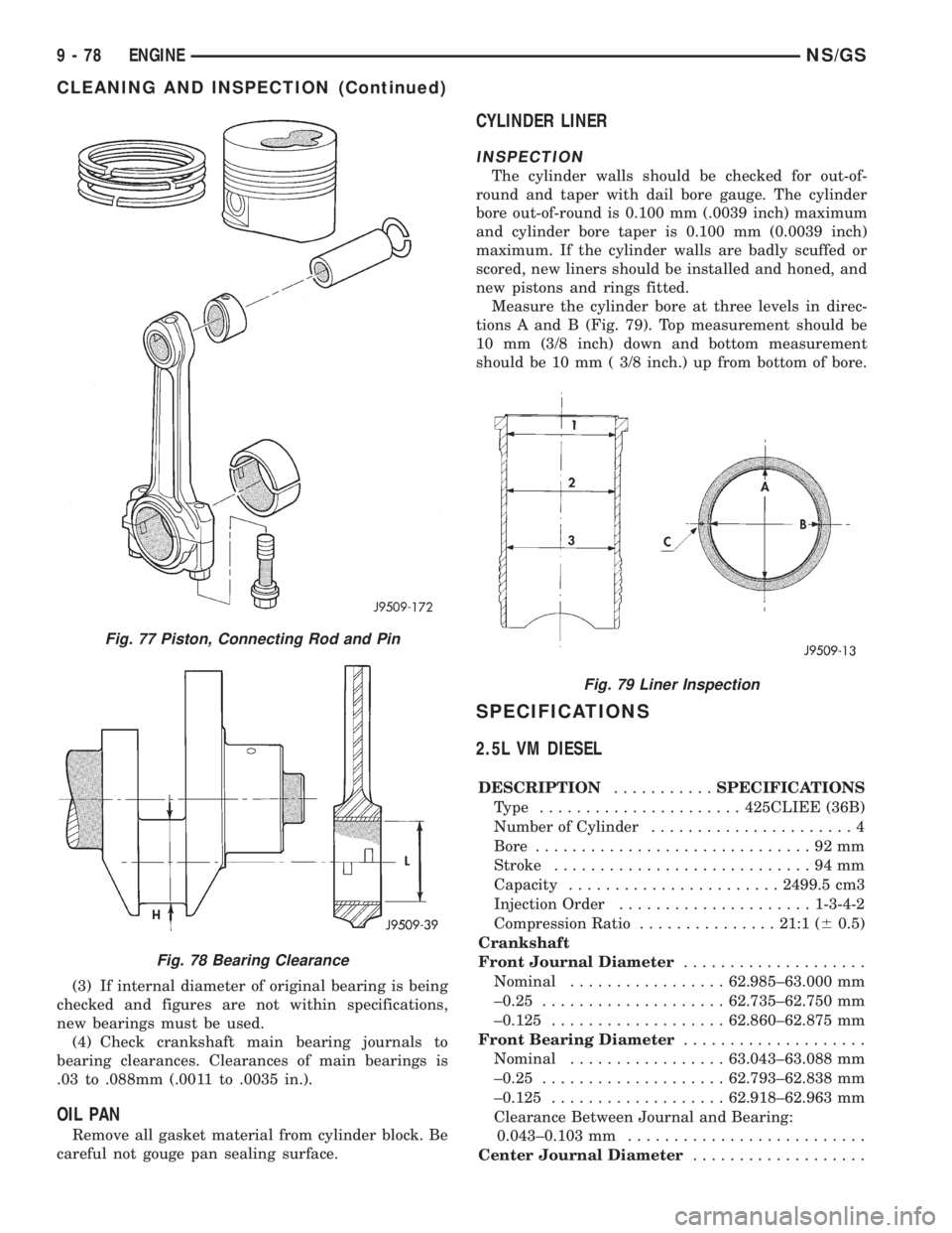
(4) Check crankshaft main bearing journals to
bearing clearances. Clearances of main bearings is
.03 to .088mm (.0011 to .0035 in.).
OIL PAN
Remove all gasket material from cylinder block. Be
careful not gouge pan sealing surface.
CYLINDER LINER
INSPECTION
The cylinder walls should be checked for out-of-
round and taper with dail bore gauge. The cylinder
bore out-of-round is 0.100 mm (.0039 inch) maximum
and cylinder bore taper is 0.100 mm (0.0039 inch)
maximum. If the cylinder walls are badly scuffed or
scored, new liners should be installed and honed, and
new pistons and rings fitted.
Measure the cylinder bore at three levels in direc-
tions A and B (Fig. 79). Top measurement should be
10 mm (3/8 inch) down and bottom measurement
should be 10 mm ( 3/8 inch.) up from bottom of bore.
SPECIFICATIONS
2.5L VM DIESEL
DESCRIPTION...........SPECIFICATIONS
Type ......................425CLIEE (36B)
Number of Cylinder......................4
Bore..............................92mm
Stroke............................94mm
Capacity.......................2499.5 cm3
Injection Order.....................1-3-4-2
Compression Ratio...............21:1 (60.5)
Crankshaft
Front Journal Diameter....................
Nominal.................62.985±63.000 mm
±0.25....................62.735±62.750 mm
±0.125...................62.860±62.875 mm
Front Bearing Diameter....................
Nominal.................63.043±63.088 mm
±0.25....................62.793±62.838 mm
±0.125...................62.918±62.963 mm
Clearance Between Journal and Bearing:
0.043±0.103 mm..........................
Center Journal Diameter...................
Fig. 77 Piston, Connecting Rod and Pin
Fig. 78 Bearing Clearance
Fig. 79 Liner Inspection
9 - 78 ENGINENS/GS
CLEANING AND INSPECTION (Continued)
Page 1270 of 1938
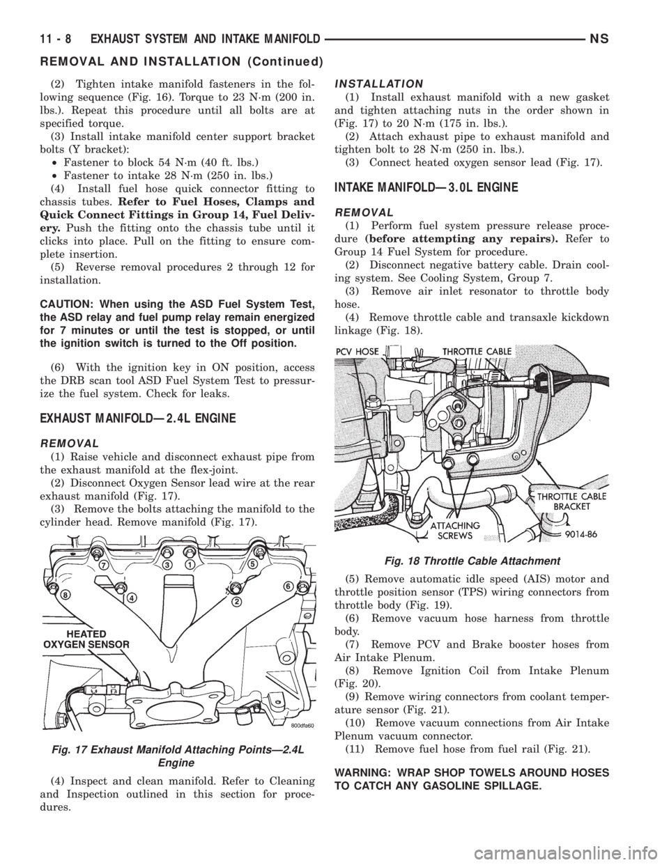
(2) Tighten intake manifold fasteners in the fol-
lowing sequence (Fig. 16). Torque to 23 N´m (200 in.
lbs.). Repeat this procedure until all bolts are at
specified torque.
(3) Install intake manifold center support bracket
bolts (Y bracket):
²Fastener to block 54 N´m (40 ft. lbs.)
²Fastener to intake 28 N´m (250 in. lbs.)
(4) Install fuel hose quick connector fitting to
chassis tubes.Refer to Fuel Hoses, Clamps and
Quick Connect Fittings in Group 14, Fuel Deliv-
ery.Push the fitting onto the chassis tube until it
clicks into place. Pull on the fitting to ensure com-
plete insertion.
(5) Reverse removal procedures 2 through 12 for
installation.
CAUTION: When using the ASD Fuel System Test,
the ASD relay and fuel pump relay remain energized
for 7 minutes or until the test is stopped, or until
the ignition switch is turned to the Off position.
(6) With the ignition key in ON position, access
the DRB scan tool ASD Fuel System Test to pressur-
ize the fuel system. Check for leaks.
EXHAUST MANIFOLDÐ2.4L ENGINE
REMOVAL
(1) Raise vehicle and disconnect exhaust pipe from
the exhaust manifold at the flex-joint.
(2) Disconnect Oxygen Sensor lead wire at the rear
exhaust manifold (Fig. 17).
(3) Remove the bolts attaching the manifold to the
cylinder head. Remove manifold (Fig. 17).
(4) Inspect and clean manifold. Refer to Cleaning
and Inspection outlined in this section for proce-
dures.
INSTALLATION
(1) Install exhaust manifold with a new gasket
and tighten attaching nuts in the order shown in
(Fig. 17) to 20 N´m (175 in. lbs.).
(2) Attach exhaust pipe to exhaust manifold and
tighten bolt to 28 N´m (250 in. lbs.).
(3) Connect heated oxygen sensor lead (Fig. 17).
INTAKE MANIFOLDÐ3.0L ENGINE
REMOVAL
(1) Perform fuel system pressure release proce-
dure(before attempting any repairs).Refer to
Group 14 Fuel System for procedure.
(2) Disconnect negative battery cable. Drain cool-
ing system. See Cooling System, Group 7.
(3) Remove air inlet resonator to throttle body
hose.
(4) Remove throttle cable and transaxle kickdown
linkage (Fig. 18).
(5) Remove automatic idle speed (AIS) motor and
throttle position sensor (TPS) wiring connectors from
throttle body (Fig. 19).
(6) Remove vacuum hose harness from throttle
body.
(7) Remove PCV and Brake booster hoses from
Air Intake Plenum.
(8) Remove Ignition Coil from Intake Plenum
(Fig. 20).
(9) Remove wiring connectors from coolant temper-
ature sensor (Fig. 21).
(10) Remove vacuum connections from Air Intake
Plenum vacuum connector.
(11) Remove fuel hose from fuel rail (Fig. 21).
WARNING: WRAP SHOP TOWELS AROUND HOSES
TO CATCH ANY GASOLINE SPILLAGE.
Fig. 17 Exhaust Manifold Attaching PointsÐ2.4L
Engine
Fig. 18 Throttle Cable Attachment
11 - 8 EXHAUST SYSTEM AND INTAKE MANIFOLDNS
REMOVAL AND INSTALLATION (Continued)
Page 1277 of 1938
(5) Make sure the injector holes are clean and all
plugs have been removed.
(6) Lube injector O-ring with a drop of clean
engine oil to ease installation.(7) Put the tip of each injector into their ports.
Push the assembly into place until the injectors are
seated in the ports (Fig. 41).
(8) Install the fuel rail attaching bolts and torque
to 22 N´m (200 in. lbs.) (Fig. 39).
(9) Install fuel tube retaining bracket screw and
torque to 4 N´m (35 in. lbs.) (Fig. 39).
(10) Connect cam sensor and coolant temperature
sensor (Fig. 40).
(11) Remove covering on lower intake manifold
and clean surface.
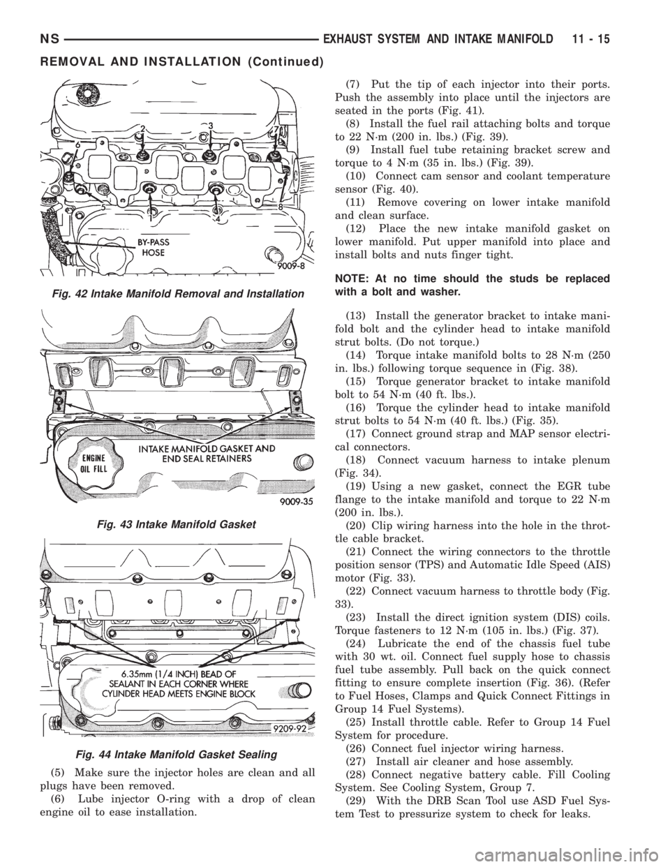
(12) Place the new intake manifold gasket on
lower manifold. Put upper manifold into place and
install bolts and nuts finger tight.
NOTE: At no time should the studs be replaced
with a bolt and washer.
(13) Install the generator bracket to intake mani-
fold bolt and the cylinder head to intake manifold
strut bolts. (Do not torque.)
(14) Torque intake manifold bolts to 28 N´m (250
in. lbs.) following torque sequence in (Fig. 38).
(15) Torque generator bracket to intake manifold
bolt to 54 N´m (40 ft. lbs.).
(16) Torque the cylinder head to intake manifold
strut bolts to 54 N´m (40 ft. lbs.) (Fig. 35).
(17) Connect ground strap and MAP sensor electri-
cal connectors.
(18) Connect vacuum harness to intake plenum
(Fig. 34).
(19) Using a new gasket, connect the EGR tube
flange to the intake manifold and torque to 22 N´m
(200 in. lbs.).
(20) Clip wiring harness into the hole in the throt-
tle cable bracket.
(21) Connect the wiring connectors to the throttle
position sensor (TPS) and Automatic Idle Speed (AIS)
motor (Fig. 33).
(22) Connect vacuum harness to throttle body (Fig.
33).
(23) Install the direct ignition system (DIS) coils.
Torque fasteners to 12 N´m (105 in. lbs.) (Fig. 37).
(24) Lubricate the end of the chassis fuel tube
with 30 wt. oil. Connect fuel supply hose to chassis
fuel tube assembly. Pull back on the quick connect
fitting to ensure complete insertion (Fig. 36). (Refer
to Fuel Hoses, Clamps and Quick Connect Fittings in
Group 14 Fuel Systems).
(25) Install throttle cable. Refer to Group 14 Fuel
System for procedure.
(26) Connect fuel injector wiring harness.
(27) Install air cleaner and hose assembly.
(28) Connect negative battery cable. Fill Cooling
System. See Cooling System, Group 7.
(29) With the DRB Scan Tool use ASD Fuel Sys-
tem Test to pressurize system to check for leaks.
Fig. 42 Intake Manifold Removal and Installation
Fig. 43 Intake Manifold Gasket
Fig. 44 Intake Manifold Gasket Sealing
NSEXHAUST SYSTEM AND INTAKE MANIFOLD 11 - 15
REMOVAL AND INSTALLATION (Continued)
Page 1306 of 1938
(9) Momentarily touch the other end of this
jumper wire to the negative terminal of the battery
for no more than 4 seconds.
(10) Place a rag or towel below the fuel line at the
quick connect to the rail.
(11) Disconnect the quick connect fitting to the
rail. Refer to Quick-Connect Fittings in this section.
(12) Return the fuel pump relay to the PDC.
(13) One or more Diagnostic Trouble Codes (DTC's)
may have been stored in the PCM memory due to the
fuel pump relay removal. The DRB scan tool must be
used to erase a DTC. Refer to group 25, On-Board
Diagnostics.
HOSES AND CLAMPS
Inspect all hose connections (clamps and quick con-
nect fittings) for completeness and leaks. Replace
cracked, scuffed, or swelled hoses. Replace hoses that
rub against other vehicle components or show sign of
wear.
Fuel injected vehicles use specially constructed
hoses. When replacing hoses, only use hoses marked
EFM/EFI.
When installing hoses, ensure that they are routed
away from contact with other vehicle components
that could rub against them and cause failure. Avoid
contact with clamps or other components that cause
abrasions or scuffing. Ensure that rubber hoses are
properly routed and avoid heat sources.
The hose clamps have rolled edges to prevent the
clamp from cutting into the hose. Only use clamps
that are original equipment or equivalent. Other
types of clamps may cut into the hoses and cause
high pressure fuel leaks. Tighten hose clamps to 1
N´m (10 in. lbs.) torque.
QUICK-CONNECT FITTINGS
REMOVAL
When disconnecting a quick-connect fitting, the
retainer will remain on the fuel tube nipple.
WARNING: RELEASE FUEL SYSTEM PRESSURE
BEFORE DISCONNECTING A QUICK-CONNECT FIT-
TINGS. REFER TO THE FUEL PRESSURE RELEASE
PROCEDURE.
(1) Disconnect negative cable from battery.
(2) Perform Fuel Pressure Release Procedure.
Refer to the Fuel Pressure Release Procedure in this
section.
(3) Squeeze retainer tabs together and pull fuel
tube/quick-connect fitting assembly off of fuel tube
nipple. The retainer will remain on fuel tube.
INSTALLATION
CAUTION: Never install a quick-connect fitting
without the retainer being either on the fuel tube or
already in the quick-connect fitting. In either case,
ensure the retainer locks securely into the quick-
connect fitting by firmly pulling on fuel tube and fit-
ting to ensure it is secured.
(1) Using a clean lint free cloth, clean the fuel tube
nipple and retainer.
(2) Prior to connecting the fitting to the fuel tube,
coat the fuel tube nipple with clean 30 weight engine
oil.
(3) Push the quick-connect fitting over the fuel
tube until theretainer seats and a click is heard.
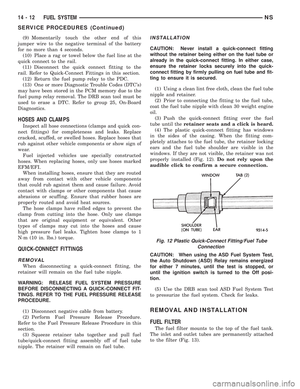
(4) The plastic quick-connect fitting has windows
in the sides of the casing. When the fitting com-
pletely attaches to the fuel tube, the retainer locking
ears and the fuel tube shoulder are visible in the
windows. If they are not visible, the retainer was not
properly installed (Fig. 12).Do not rely upon the
audible click to confirm a secure connection.
CAUTION: When using the ASD Fuel System Test,
the Auto Shutdown (ASD) Relay remains energized
for either 7 minutes, until the test is stopped, or
until the ignition switch is turned to the Off posi-
tion.
(5) Use the DRB scan tool ASD Fuel System Test
to pressurize the fuel system. Check for leaks.
REMOVAL AND INSTALLATION
FUEL FILTER
The fuel filter mounts to the top of the fuel tank.
The inlet and outlet tubes are permanently attached
to the filter (Fig. 13).
Fig. 12 Plastic Quick-Connect Fitting/Fuel Tube
Connection
14 - 12 FUEL SYSTEMNS
SERVICE PROCEDURES (Continued)