1996 CHRYSLER VOYAGER cooling
[x] Cancel search: coolingPage 1387 of 1938
INSTALLATION
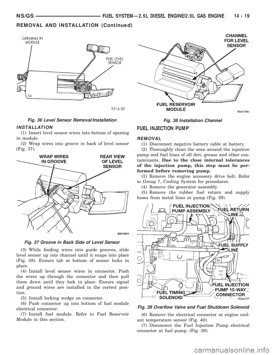
(1) Insert level sensor wires into bottom of opening
in module.
(2) Wrap wires into groove in back of level sensor
(Fig. 37).
(3) While feeding wires into guide grooves, slide
level sensor up into channel until it snaps into place
(Fig. 38). Ensure tab at bottom of sensor locks in
place.
(4) Install level sensor wires in connector. Push
the wires up through the connector and then pull
them down until they lock in place. Ensure signal
and ground wires are installed in the correct posi-
tion.
(5) Install locking wedge on connector.
(6) Push connector up into bottom of fuel module
electrical connector.
(7) Install fuel module. Refer to Fuel Reservoir
Module in this section.FUEL INJECTION PUMP
REMOVAL
(1) Disconnect negative battery cable at battery.
(2) Thoroughly clean the area around the injection
pump and fuel lines of all dirt, grease and other con-
taminants.Due to the close internal tolerances
of the injection pump, this step must be per-
formed before removing pump.
(3) Remove the engine accessory drive belt. Refer
to Group 7, Cooling System for procedures.
(4) Remove the generator assembly.
(5) Remove the rubber fuel return and supply
hoses from metal lines at pump (Fig. 39).
(6) Remove the electrical connector at engine cool-
ant temperature sensor (Fig. 40).
(7) Disconnect the Fuel Injection Pump electrical
connector at fuel pump. (Fig. 39).
Fig. 36 Level Sensor Removal/Installation
Fig. 37 Groove in Back Side of Level Sensor
Fig. 38 Installation Channel
Fig. 39 Overflow Valve and Fuel Shutdown Solenoid
NS/GSFUEL SYSTEMÐ2.5L DIESEL ENGINE/2.0L GAS ENGINE 14 - 19
REMOVAL AND INSTALLATION (Continued)
Page 1390 of 1938
(14) Gauge reading should be at 0.60 mm. If not,
the pump must be rotated for adjustment:
(a) Loosen the three injection pump mounting
nuts at the mounting flanges. These flanges are
equipped with slotted holes. The slotted holes are
used to rotate and position the injection pump for
fuel timing. Loosen the three nuts just enough to
rotate the pump.
(b) Rotate the pumpclockwise(as viewed from
front) until .60 mm is indicated on the dial indica-
tor gauge.
(c) Tighten the three pump mounting nuts to 30
N´m (22 ft. lbs.) torque.
(d) Recheck the dial indicator after tightening
the pump mounting nuts. Gauge should still be
reading 0.60 mm. Loosen pump mounting nuts and
readjust if necessary.
(15) Remove dial indicator and adapter tools.
(16) Install access plug and washer to rear of
injection pump.
(17) Install plug at timing gear cover.
(18) Remove dial indicator from valve stem.
(19) Install valve spring and keepers.
(20) Install rocker arm assembly and tighten nuts.
(21) Install and connect the four high±pressure
fuel lines to the fuel injection pump. Also connect
fuel lines at the fuel injectors. For procedures, refer
to High±Pressure Fuel Lines in this group.
(22) Install electrical connector at engine coolant
temperature sensor.
(23) Connect electrical connector at fuel shutdown
solenoid.(24) Connect the main engine wiring harness to
the glow plugs.
(25) Connect the fuel timing solenoid pigtail har-
ness to the engine wiring harness.
(26) Connect the overflow valve/banjo fitting (fuel
return line assembly). Replace copper gaskets before
installing.
(27) Connect the rubber fuel return and supply
hoses to metal lines at pump. Tighten hose clamps to
2 N´m (20 in. lbs.) torque.
(28) Install generator assembly.
(29) Install engine accessory drive belt. Refer to
Group 7, Cooling System for procedures.
(30) Install negative battery cable to battery.
(31) Start the engine and bring to normal operat-
ing temperature.
(32) Check for fuel leaks.
FUEL INJECTORS
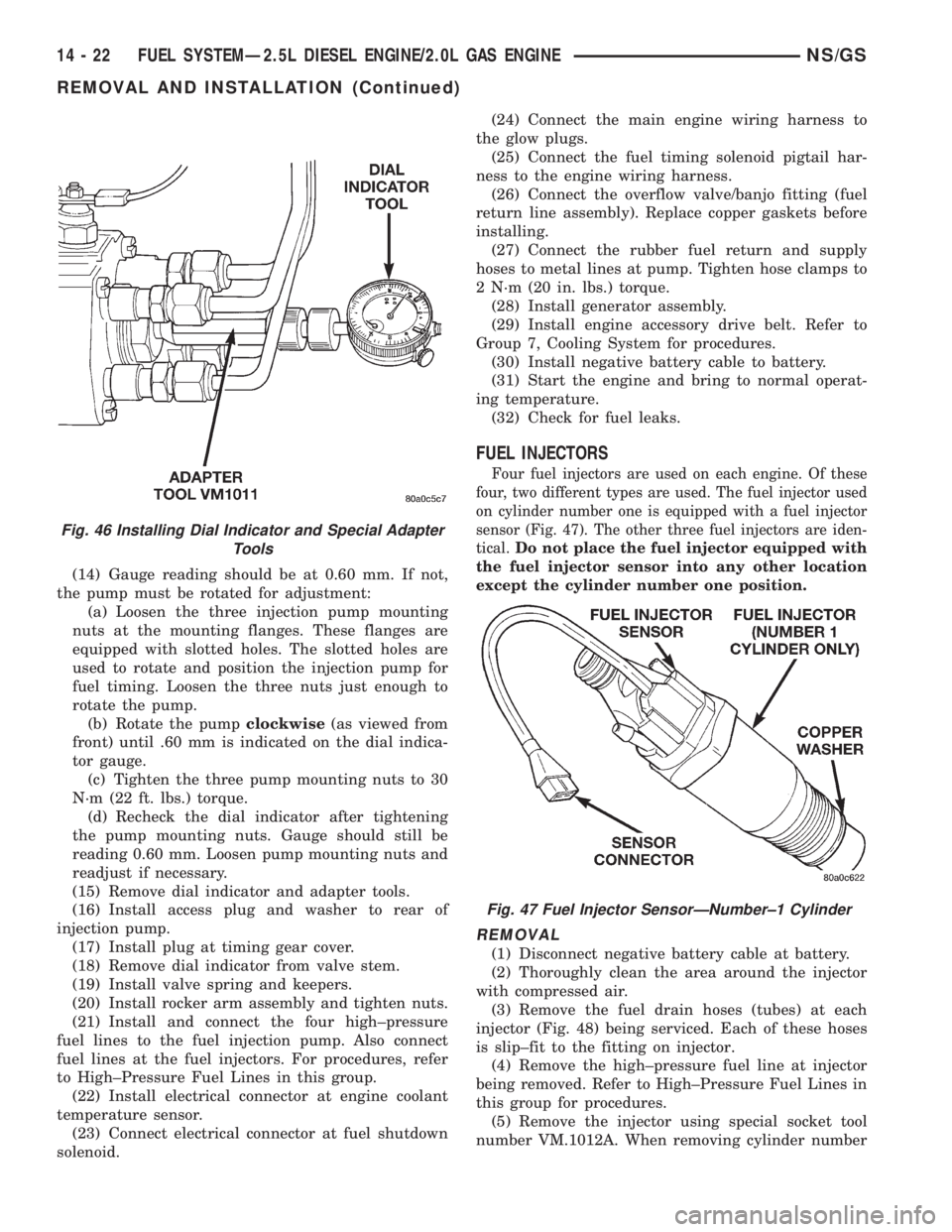
Four fuel injectors are used on each engine. Of these
four, two different types are used. The fuel injector used
on cylinder number one is equipped with a fuel injector
sensor (Fig. 47). The other three fuel injectors are iden-
tical.
Do not place the fuel injector equipped with
the fuel injector sensor into any other location
except the cylinder number one position.
REMOVAL
(1) Disconnect negative battery cable at battery.
(2) Thoroughly clean the area around the injector
with compressed air.
(3) Remove the fuel drain hoses (tubes) at each
injector (Fig. 48) being serviced. Each of these hoses
is slip±fit to the fitting on injector.
(4) Remove the high±pressure fuel line at injector
being removed. Refer to High±Pressure Fuel Lines in
this group for procedures.
(5) Remove the injector using special socket tool
number VM.1012A. When removing cylinder number
Fig. 46 Installing Dial Indicator and Special Adapter
Tools
Fig. 47 Fuel Injector SensorÐNumber±1 Cylinder
14 - 22 FUEL SYSTEMÐ2.5L DIESEL ENGINE/2.0L GAS ENGINENS/GS
REMOVAL AND INSTALLATION (Continued)
Page 1409 of 1938
Connect the DVM between the center and sensor
ground terminal. Refer to Group 8W - Wiring Dia-
grams for correct pinout.
With the ignition switch in the ON position, check
the output voltage at the center terminal wire of the
connector. Check the output voltage at idle and at
Wide-Open-Throttle (WOT). At idle, TPS output volt-
age should be approximately 0.38 volts to 1.2 volts.
At wide open throttle, TPS output voltage should be
approximately 3.1 volts to 4.4 volts. The output volt-
age should gradually increase as the throttle plate
moves slowly from idle to WOT.
Check for spread terminals at the sensor and PCM
connections before replacing the TPS.
THROTTLE BODY MINIMUM AIR FLOW
(1) Turn ignition key to Off.
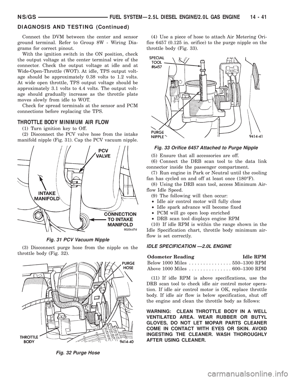
(2) D
isconnect the PCV valve hose from the intake
manifold nipple (Fig. 31). Cap the PCV vacuum nipple.
(3) Disconnect purge hose from the nipple on the
throttle body (Fig. 32).(4) Use a piece of hose to attach Air Metering Ori-
fice 6457 (0.125 in. orifice) to the purge nipple on the
throttle body (Fig. 33).
(5) Ensure that all accessories are off.
(6) Connect the DRB scan tool to the data link
connector inside the passenger compartment.
(7) Run engine in Park or Neutral until the cooling
fan has cycled on and off at least once (180ÉF).
(8) Using the DRB scan tool, access Minimum Air-
flow Idle Speed.
(9) The following will then occur:
²Idle air control motor will fully close
²Idle spark advance will become fixed
²PCM will go open loop enriched
²DRB scan tool displays engine RPM
(10) If idle RPM is within the range shown in the
Idle Specification chart, throttle body minimum air-
flow is set correctly.IDLE SPECIFICATION Ð2.0L ENGINE
Odometer Reading Idle RPM
Below 1000 Miles...............550±1300 RPM
Above 1000 Miles...............600±1300 RPM
(11) If idle RPM is above specifications, use the
DRB scan tool to check idle air control motor opera-
tion. If idle air control motor is OK, replace throttle
body. If idle air flow is below specification, shut off
the engine and clean the throttle body as follows:
WARNING: CLEAN THROTTLE BODY IN A WELL
VENTILATED AREA. WEAR RUBBER OR BUTYL
GLOVES, DO NOT LET MOPAR PARTS CLEANER
COME IN CONTACT WITH EYES OR SKIN. AVOID
INGESTING THE CLEANER. WASH THOROUGHLY
AFTER USING CLEANER.
Fig. 31 PCV Vacuum Nipple
Fig. 32 Purge Hose
Fig. 33 Orifice 6457 Attached to Purge Nipple
NS/GSFUEL SYSTEMÐ2.5L DIESEL ENGINE/2.0L GAS ENGINE 14 - 41
DIAGNOSIS AND TESTING (Continued)
Page 1413 of 1938
BOOST PRESSURE SENSOR
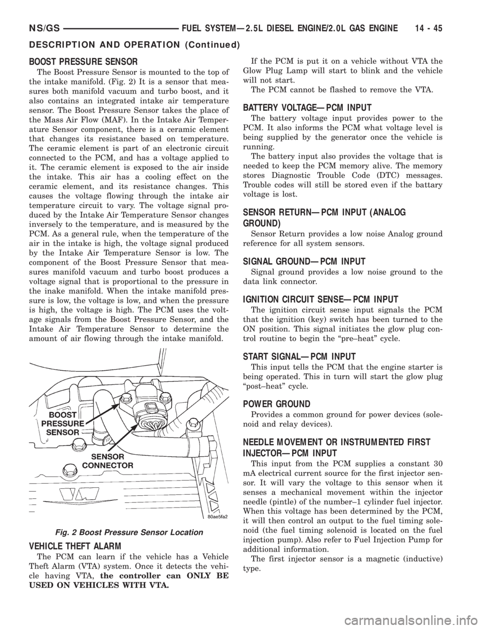
The Boost Pressure Sensor is mounted to the top of
the intake manifold. (Fig. 2) It is a sensor that mea-
sures both manifold vacuum and turbo boost, and it
also contains an integrated intake air temperature
sensor. The Boost Pressure Sensor takes the place of
the Mass Air Flow (MAF). In the Intake Air Temper-
ature Sensor component, there is a ceramic element
that changes its resistance based on temperature.
The ceramic element is part of an electronic circuit
connected to the PCM, and has a voltage applied to
it. The ceramic element is exposed to the air inside
the intake. This air has a cooling effect on the
ceramic element, and its resistance changes. This
causes the voltage flowing through the intake air
temperature circuit to vary. The voltage signal pro-
duced by the Intake Air Temperature Sensor changes
inversely to the temperature, and is measured by the
PCM. As a general rule, when the temperature of the
air in the intake is high, the voltage signal produced
by the Intake Air Temperature Sensor is low. The
component of the Boost Pressure Sensor that mea-
sures manifold vacuum and turbo boost produces a
voltage signal that is proportional to the pressure in
the inake manifold. When the intake manifold pres-
sure is low, the voltage is low, and when the pressure
is high, the voltage is high. The PCM uses the volt-
age signals from the Boost Pressure Sensor, and the
Intake Air Temperature Sensor to determine the
amount of air flowing through the intake manifold.
VEHICLE THEFT ALARM
The PCM can learn if the vehicle has a Vehicle
Theft Alarm (VTA) system. Once it detects the vehi-
cle having VTA,the controller can ONLY BE
USED ON VEHICLES WITH VTA.If the PCM is put it on a vehicle without VTA the
Glow Plug Lamp will start to blink and the vehicle
will not start.
The PCM cannot be flashed to remove the VTA.
BATTERY VOLTAGEÐPCM INPUT
The battery voltage input provides power to the
PCM. It also informs the PCM what voltage level is
being supplied by the generator once the vehicle is
running.
The battery input also provides the voltage that is
needed to keep the PCM memory alive. The memory
stores Diagnostic Trouble Code (DTC) messages.
Trouble codes will still be stored even if the battary
voltage is lost.
SENSOR RETURNÐPCM INPUT (ANALOG
GROUND)
Sensor Return provides a low noise Analog ground
reference for all system sensors.
SIGNAL GROUNDÐPCM INPUT
Signal ground provides a low noise ground to the
data link connector.
IGNITION CIRCUIT SENSEÐPCM INPUT
The ignition circuit sense input signals the PCM
that the ignition (key) switch has been turned to the
ON position. This signal initiates the glow plug con-
trol routine to begin the ªpre±heatº cycle.
START SIGNALÐPCM INPUT
This input tells the PCM that the engine starter is
being operated. This in turn will start the glow plug
ªpost±heatº cycle.
POWER GROUND
Provides a common ground for power devices (sole-
noid and relay devices).
NEEDLE MOVEMENT OR INSTRUMENTED FIRST
INJECTORÐPCM INPUT
This input from the PCM supplies a constant 30
mA electrical current source for the first injector sen-
sor. It will vary the voltage to this sensor when it
senses a mechanical movement within the injector
needle (pintle) of the number±1 cylinder fuel injector.
When this voltage has been determined by the PCM,
it will then control an output to the fuel timing sole-
noid (the fuel timing solenoid is located on the fuel
injection pump). Also refer to Fuel Injection Pump for
additional information.
The first injector sensor is a magnetic (inductive)
type.
Fig. 2 Boost Pressure Sensor Location
NS/GSFUEL SYSTEMÐ2.5L DIESEL ENGINE/2.0L GAS ENGINE 14 - 45
DESCRIPTION AND OPERATION (Continued)
Page 1422 of 1938
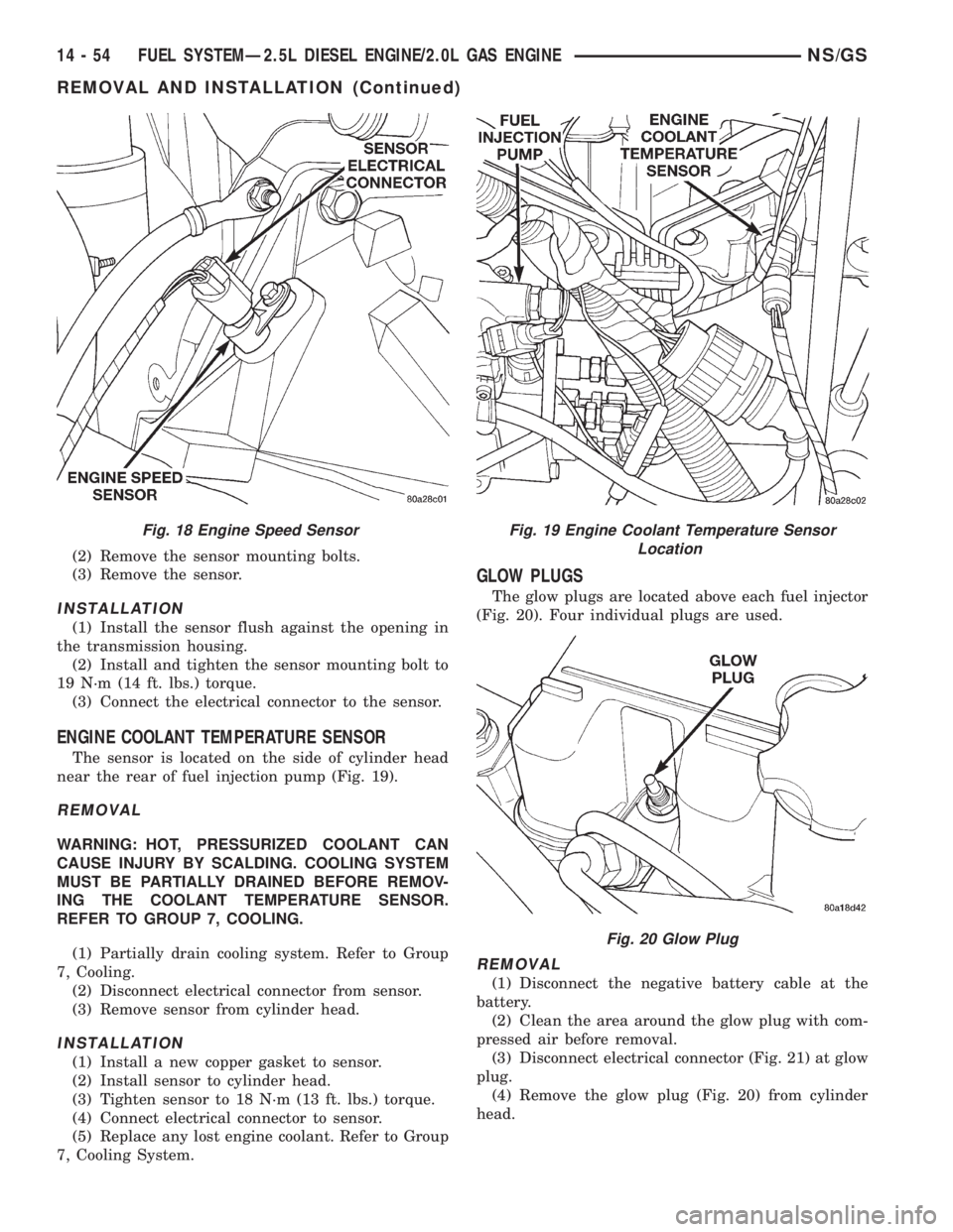
(2) Remove the sensor mounting bolts.
(3) Remove the sensor.
INSTALLATION
(1) Install the sensor flush against the opening in
the transmission housing.
(2) Install and tighten the sensor mounting bolt to
19 N´m (14 ft. lbs.) torque.
(3) Connect the electrical connector to the sensor.
ENGINE COOLANT TEMPERATURE SENSOR
The sensor is located on the side of cylinder head
near the rear of fuel injection pump (Fig. 19).
REMOVAL
WARNING: HOT, PRESSURIZED COOLANT CAN
CAUSE INJURY BY SCALDING. COOLING SYSTEM
MUST BE PARTIALLY DRAINED BEFORE REMOV-
ING THE COOLANT TEMPERATURE SENSOR.
REFER TO GROUP 7, COOLING.
(1) Partially drain cooling system. Refer to Group
7, Cooling.
(2) Disconnect electrical connector from sensor.
(3) Remove sensor from cylinder head.
INSTALLATION
(1) Install a new copper gasket to sensor.
(2) Install sensor to cylinder head.
(3) Tighten sensor to 18 N´m (13 ft. lbs.) torque.
(4) Connect electrical connector to sensor.
(5) Replace any lost engine coolant. Refer to Group
7, Cooling System.
GLOW PLUGS
The glow plugs are located above each fuel injector
(Fig. 20). Four individual plugs are used.
REMOVAL
(1) Disconnect the negative battery cable at the
battery.
(2) Clean the area around the glow plug with com-
pressed air before removal.
(3) Disconnect electrical connector (Fig. 21) at glow
plug.
(4) Remove the glow plug (Fig. 20) from cylinder
head.
Fig. 18 Engine Speed SensorFig. 19 Engine Coolant Temperature Sensor
Location
Fig. 20 Glow Plug
14 - 54 FUEL SYSTEMÐ2.5L DIESEL ENGINE/2.0L GAS ENGINENS/GS
REMOVAL AND INSTALLATION (Continued)
Page 1437 of 1938
REMOVAL AND INSTALLATION
2.4 LITER POWER STEERING PUMP
REMOVE
WARNING: POWER STEERING OIL, ENGINE COM-
PONENTS AND THE EXHAUST SYSTEM MAY BE
EXTREMELY HOT IF ENGINE HAS BEEN RUNNING.
DO NOT START ENGINE WITH ANY LOOSE OR DIS-
CONNECTED HOSES. DO NOT ALLOW HOSES TO
TOUCH HOT EXHAUST MANIFOLD OR CATALYST.
(1) Remove cap from power steering fluid reser-
voir.
(2) Using a siphon pump, remove as much power
steering fluid as possible from the power steering
fluid reservoir.
(3) Remove the (-) negative battery cable from the
battery and isolate cable.
(4) Remove the drive belt from the power steering
pump pulley. See Cooling, Group 7 for detailed
removal procedure.
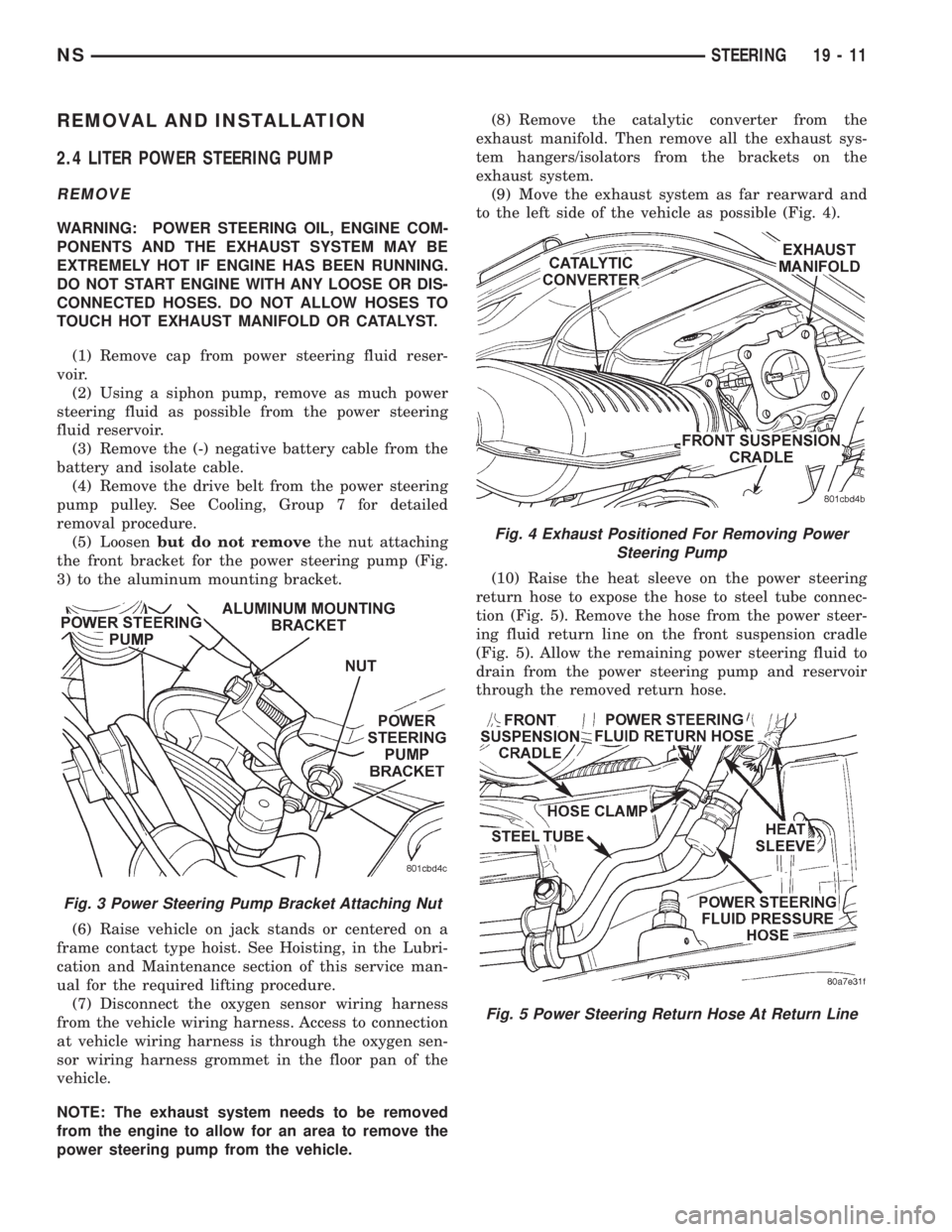
(5) Loosenbut do not removethe nut attaching
the front bracket for the power steering pump (Fig.
3) to the aluminum mounting bracket.
(6) Raise vehicle on jack stands or centered on a
frame contact type hoist. See Hoisting, in the Lubri-
cation and Maintenance section of this service man-
ual for the required lifting procedure.
(7) Disconnect the oxygen sensor wiring harness
from the vehicle wiring harness. Access to connection
at vehicle wiring harness is through the oxygen sen-
sor wiring harness grommet in the floor pan of the
vehicle.
NOTE: The exhaust system needs to be removed
from the engine to allow for an area to remove the
power steering pump from the vehicle.(8) Remove the catalytic converter from the
exhaust manifold. Then remove all the exhaust sys-
tem hangers/isolators from the brackets on the
exhaust system.
(9) Move the exhaust system as far rearward and
to the left side of the vehicle as possible (Fig. 4).
(10) Raise the heat sleeve on the power steering
return hose to expose the hose to steel tube connec-
tion (Fig. 5). Remove the hose from the power steer-
ing fluid return line on the front suspension cradle
(Fig. 5). Allow the remaining power steering fluid to
drain from the power steering pump and reservoir
through the removed return hose.
Fig. 3 Power Steering Pump Bracket Attaching Nut
Fig. 4 Exhaust Positioned For Removing Power
Steering Pump
Fig. 5 Power Steering Return Hose At Return Line
NSSTEERING 19 - 11
Page 1439 of 1938
(18) Remove the 3 previously loosened bolts
attaching the front bracket to the power steering
pump and separate the power steering pump from
the front bracket prior to removing the pump from
the vehicle.
(19) The power steering pump is removed from the
vehicle by pulling it out through the exhaust tunnel
area in the floor pan of the vehicle.
INSTALL
(1) Install power steering pump back in vehicle
using the reverse order of its removal through the
exhaust tunnel are of the vehicle.
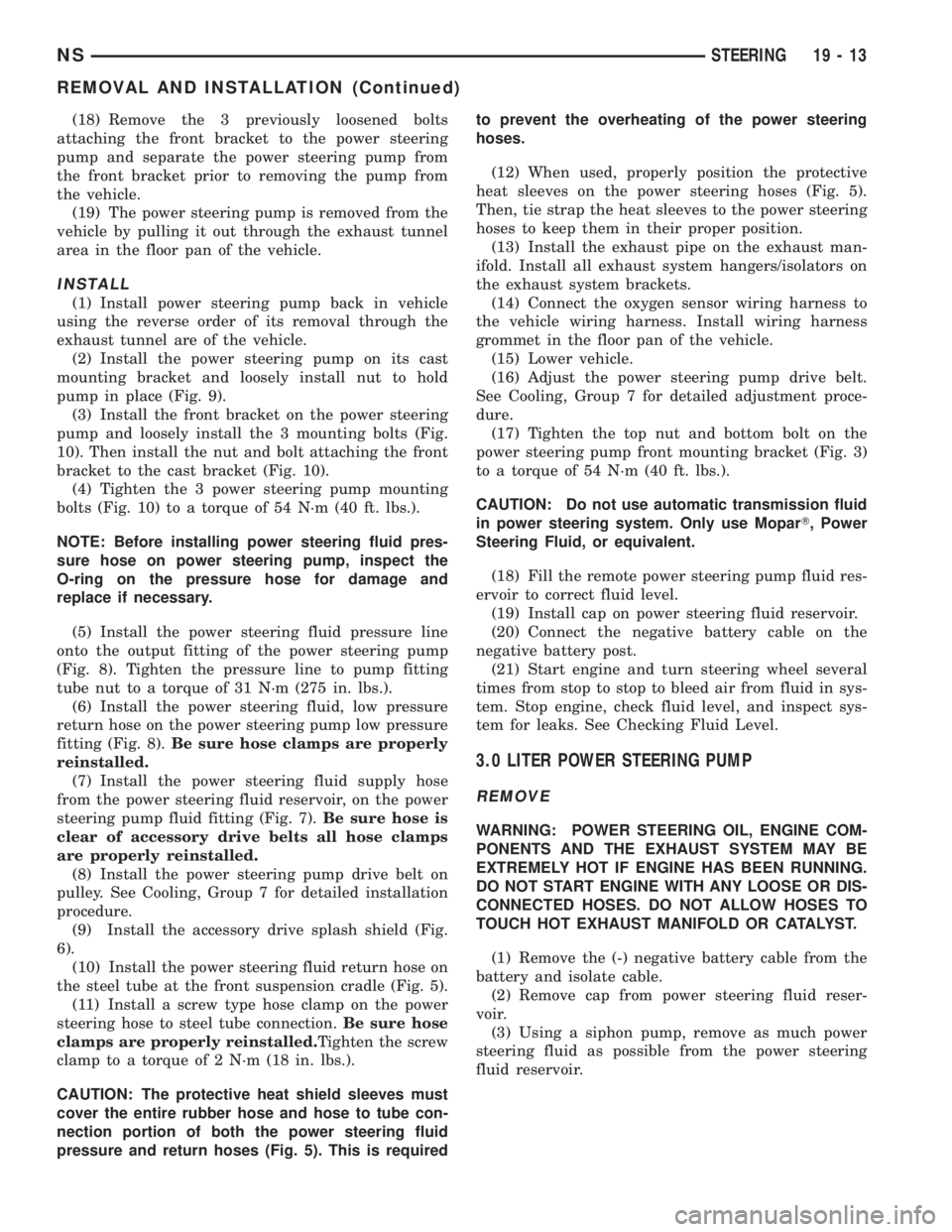
(2) Install the power steering pump on its cast
mounting bracket and loosely install nut to hold
pump in place (Fig. 9).
(3) Install the front bracket on the power steering
pump and loosely install the 3 mounting bolts (Fig.
10). Then install the nut and bolt attaching the front
bracket to the cast bracket (Fig. 10).
(4) Tighten the 3 power steering pump mounting
bolts (Fig. 10) to a torque of 54 N´m (40 ft. lbs.).
NOTE: Before installing power steering fluid pres-
sure hose on power steering pump, inspect the
O-ring on the pressure hose for damage and
replace if necessary.
(5) Install the power steering fluid pressure line
onto the output fitting of the power steering pump
(Fig. 8). Tighten the pressure line to pump fitting
tube nut to a torque of 31 N´m (275 in. lbs.).
(6) Install the power steering fluid, low pressure
return hose on the power steering pump low pressure
fitting (Fig. 8).Be sure hose clamps are properly
reinstalled.
(7) Install the power steering fluid supply hose
from the power steering fluid reservoir, on the power
steering pump fluid fitting (Fig. 7).Be sure hose is
clear of accessory drive belts all hose clamps
are properly reinstalled.
(8) Install the power steering pump drive belt on
pulley. See Cooling, Group 7 for detailed installation
procedure.
(9) Install the accessory drive splash shield (Fig.
6).
(10) Install the power steering fluid return hose on
the steel tube at the front suspension cradle (Fig. 5).
(11) Install a screw type hose clamp on the power
steering hose to steel tube connection.Be sure hose
clamps are properly reinstalled.Tighten the screw
clamp to a torque of 2 N´m (18 in. lbs.).
CAUTION: The protective heat shield sleeves must
cover the entire rubber hose and hose to tube con-
nection portion of both the power steering fluid
pressure and return hoses (Fig. 5). This is requiredto prevent the overheating of the power steering
hoses.
(12) When used, properly position the protective
heat sleeves on the power steering hoses (Fig. 5).
Then, tie strap the heat sleeves to the power steering
hoses to keep them in their proper position.
(13) Install the exhaust pipe on the exhaust man-
ifold. Install all exhaust system hangers/isolators on
the exhaust system brackets.
(14) Connect the oxygen sensor wiring harness to
the vehicle wiring harness. Install wiring harness
grommet in the floor pan of the vehicle.
(15) Lower vehicle.
(16) Adjust the power steering pump drive belt.
See Cooling, Group 7 for detailed adjustment proce-
dure.
(17) Tighten the top nut and bottom bolt on the
power steering pump front mounting bracket (Fig. 3)
to a torque of 54 N´m (40 ft. lbs.).
CAUTION: Do not use automatic transmission fluid
in power steering system. Only use MoparT, Power
Steering Fluid, or equivalent.
(18) Fill the remote power steering pump fluid res-
ervoir to correct fluid level.
(19) Install cap on power steering fluid reservoir.
(20) Connect the negative battery cable on the
negative battery post.
(21) Start engine and turn steering wheel several
times from stop to stop to bleed air from fluid in sys-
tem. Stop engine, check fluid level, and inspect sys-
tem for leaks. See Checking Fluid Level.
3.0 LITER POWER STEERING PUMP
REMOVE
WARNING: POWER STEERING OIL, ENGINE COM-
PONENTS AND THE EXHAUST SYSTEM MAY BE
EXTREMELY HOT IF ENGINE HAS BEEN RUNNING.
DO NOT START ENGINE WITH ANY LOOSE OR DIS-
CONNECTED HOSES. DO NOT ALLOW HOSES TO
TOUCH HOT EXHAUST MANIFOLD OR CATALYST.
(1) Remove the (-) negative battery cable from the
battery and isolate cable.
(2) Remove cap from power steering fluid reser-
voir.
(3) Using a siphon pump, remove as much power
steering fluid as possible from the power steering
fluid reservoir.
NSSTEERING 19 - 13
REMOVAL AND INSTALLATION (Continued)
Page 1440 of 1938
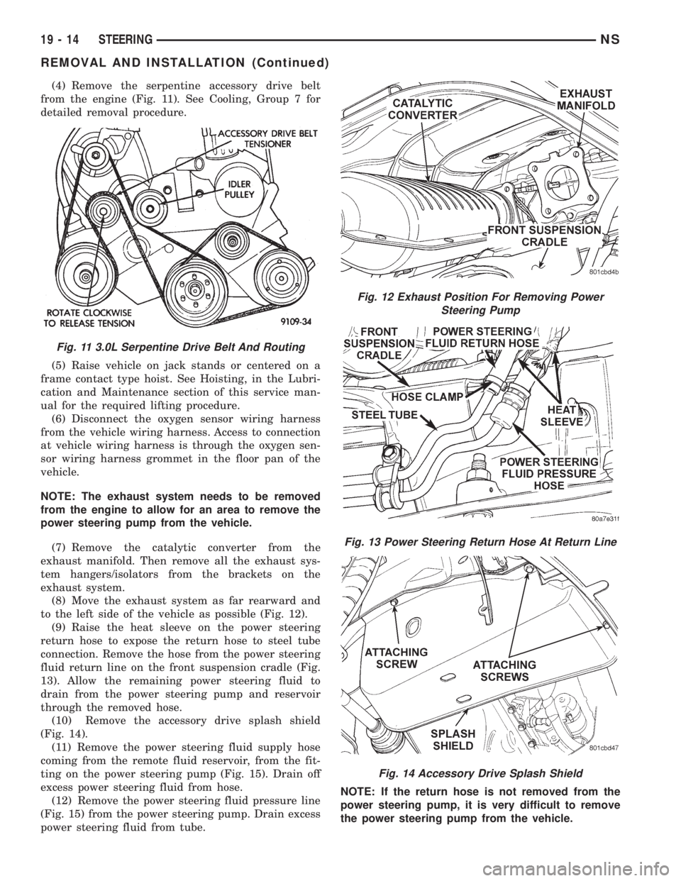
(4) Remove the serpentine accessory drive belt
from the engine (Fig. 11). See Cooling, Group 7 for
detailed removal procedure.
(5) Raise vehicle on jack stands or centered on a
frame contact type hoist. See Hoisting, in the Lubri-
cation and Maintenance section of this service man-
ual for the required lifting procedure.
(6) Disconnect the oxygen sensor wiring harness
from the vehicle wiring harness. Access to connection
at vehicle wiring harness is through the oxygen sen-
sor wiring harness grommet in the floor pan of the
vehicle.
NOTE: The exhaust system needs to be removed
from the engine to allow for an area to remove the
power steering pump from the vehicle.
(7) Remove the catalytic converter from the
exhaust manifold. Then remove all the exhaust sys-
tem hangers/isolators from the brackets on the
exhaust system.
(8) Move the exhaust system as far rearward and
to the left side of the vehicle as possible (Fig. 12).
(9) Raise the heat sleeve on the power steering
return hose to expose the return hose to steel tube
connection. Remove the hose from the power steering
fluid return line on the front suspension cradle (Fig.
13). Allow the remaining power steering fluid to
drain from the power steering pump and reservoir
through the removed hose.
(10) Remove the accessory drive splash shield
(Fig. 14).
(11) Remove the power steering fluid supply hose
coming from the remote fluid reservoir, from the fit-
ting on the power steering pump (Fig. 15). Drain off
excess power steering fluid from hose.
(12) Remove the power steering fluid pressure line
(Fig. 15) from the power steering pump. Drain excess
power steering fluid from tube.NOTE: If the return hose is not removed from the
power steering pump, it is very difficult to remove
the power steering pump from the vehicle.
Fig. 11 3.0L Serpentine Drive Belt And Routing
Fig. 12 Exhaust Position For Removing Power
Steering Pump
Fig. 13 Power Steering Return Hose At Return Line
Fig. 14 Accessory Drive Splash Shield
19 - 14 STEERINGNS
REMOVAL AND INSTALLATION (Continued)