1996 CHRYSLER VOYAGER cooling
[x] Cancel search: coolingPage 1278 of 1938

CAUTION: When using the ASD Fuel System Test,
The Auto Shutdown (ASD) Relay will remain ener-
gized for 7 minutes or until the ignition switch is
turned to the OFF position, or Stop All Test is
selected.
EXHAUST MANIFOLDSÐ3.3/3.8L ENGINE
REMOVAL
(1) Disconnect battery negative cable.
(2) Remove accessory drive belt. Refer to Accessory
Drive section located in Group 7 Cooling System for
procedure.
(3) Remove generator.
(4) Raise vehicle and disconnect exhaust pipe
from rear (cowl side) exhaust manifold at flex-joint.
(5) Disconnect down stream oxygen sensor connec-
tor.
(6) Lower exhaust system to gain access to rear
manifold.
(7) Separate EGR tube from rear manifold and
disconnect Heated Oxygen Sensor lead wire (Fig. 45).
(8) Remove heat shield from rear engine mount.
(9) Remove Generator/Power Steering Support
Strut (Fig. 45).
(10) Remove bolts attaching crossover pipe to
manifold (Fig. 45).
(11) Disconnect up stream oxygen sensor connec-
tor.
(12) Remove bolts attaching rear manifold to cyl-
inder head and remove manifold.
(13) Lower vehicle and remove screws attaching
front heat shield to front manifold (Fig. 46).
(14) Remove bolts fastening crossover pipe to
front exhaust manifold and nuts fastening manifold
to cylinder head. Remove assemblies (Fig. 47).
(15) Inspect and clean manifold. Refer to Cleaning
and Inspection outlined in this section for proce-
dures.
INSTALLATION
(1) Install rear exhaust manifold and tighten
attaching bolts to 23 N´m (200 in. lbs.).
(2) Install generator.
NOTE: Inspect crossover pipe fasteners for dam-
age from heat and corrosion. Replace if necessary.
(3) Using new gasket attach crossover pipe to
exhaust manifold and tighten bolts to 54 N´m (40 ft.
lbs.) and connect oxygen sensor lead (Fig. 45).
(4) Install EGR Tube and Generator/Power Steer-
ing Strut (Fig. 45).
(5) Using new gaskets install front exhaust mani-
fold and tighten attaching bolts to 23 N´m (200 in.
lbs.).(6) Attach exhaust crossover with a new gasket
and tighten fasteners to 54 N´m (40 ft. lbs.) (Fig. 47).
(7) Connect up stream oxygen sensor connector.
(8) Install exhaust system.
Fig. 45 EGR Tube, Heated Oxygen Sensor and
Generator/Power Steering Strut
Fig. 46 Heat ShieldÐFront
Fig. 47 Crossover Pipe
11 - 16 EXHAUST SYSTEM AND INTAKE MANIFOLDNS
REMOVAL AND INSTALLATION (Continued)
Page 1279 of 1938
(9) Attach exhaust pipe to exhaust manifold using
new gasket and tighten bolts to 28 N´m (250 in. lbs.).
(10) Connect down stream oxygen sensor connec-
tor.
(11) Install front manifold heat shield and tighten
attaching screws to 12 N´m (105 in. lbs.) (Fig. 46).
(12) Install accessory drive belt. Refer to Accessory
Drive section located in Group 7 Cooling System for
procedure.
(13) Connect battery negative cable.
CLEANING AND INSPECTION
INTAKE MANIFOLD
INSPECTION
Check for:
²Damage and cracks of each section.
²Clogged water passages in end cross-overs (if
equipped).
²Check for cylinder head mounting surface distor-
tion using a straightedge and thickness gauge. Refer
to specifications for warpage specification.
CLEANING
Remove the gasket material from the manifold sur-
faces.
Be careful not to gouge or scratch the sealing sur-
face.
EXHAUST MANIFOLD
INSPECTION
Inspect exhaust manifolds for damage or cracks
and check distortion of the cylinder head mounting
surface and exhaust cross-over mounting surface
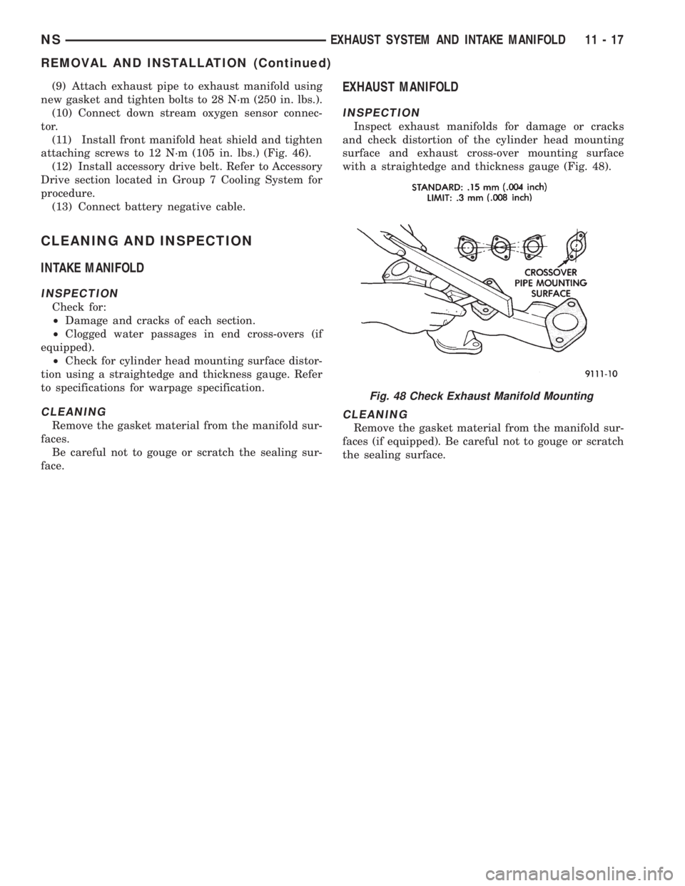
with a straightedge and thickness gauge (Fig. 48).
CLEANING
Remove the gasket material from the manifold sur-
faces (if equipped). Be careful not to gouge or scratch
the sealing surface.
Fig. 48 Check Exhaust Manifold Mounting
NSEXHAUST SYSTEM AND INTAKE MANIFOLD 11 - 17
REMOVAL AND INSTALLATION (Continued)
Page 1324 of 1938
THROTTLE BODY....................... 64
THROTTLE POSITION SENSOR............ 65
UPSTREAM OXYGEN SENSOR............. 68
SPECIFICATIONS
TORQUE.............................. 72SPECIAL TOOLS
FUEL................................. 72
GENERAL INFORMATION
INTRODUCTION
All engines used in this section have a sequential
Multi-Port Electronic Fuel Injection system. The MPI
system is computer regulated and provides precise
air/fuel ratios for all driving conditions. The Power-
train Control Module (PCM) operates the fuel injec-
tion system.
The PCM regulates:
²Ignition timing
²Air/fuel ratio
²Emission control devices
²Cooling fan
²Charging system
²Idle speed
²Vehicle speed control
Various sensors provide the inputs necessary for
the PCM to correctly operate these systems. In addi-
tion to the sensors, various switches also provide
inputs to the PCM.
All inputs to the PCM are converted into signals.
The PCM can adapt its programming to meet chang-
ing operating conditions.
Fuel is injected into the intake port above the
intake valve in precise metered amounts through
electrically operated injectors. The PCM fires the
injectors in a specific sequence. Under most operat-
ing conditions, the PCM maintains an air fuel ratio
of 14.7 parts air to 1 part fuel by constantly adjust-
ing injector pulse width. Injector pulse width is the
length of time the injector is open.
The PCM adjusts injector pulse width by opening
and closing the ground path to the injector. Engine
RPM (speed) and manifold absolute pressure (air
density) are the primary inputs that determine injec-
tor pulse width.
MODES OF OPERATION
As input signals to the PCM change, the PCM
adjusts its response to output devices. For example,
the PCM must calculate a different injector pulse
width and ignition timing for idle than it does for
Wide Open Throttle (WOT). There are several differ-
ent modes of operation that determine how the PCM
responds to the various input signals.
There are two different areas of operation, OPEN
LOOP and CLOSED LOOP.
During OPEN LOOP modes the PCM receives
input signals and responds according to preset PCMprogramming. Input from the oxygen (O2S) sensor is
not monitored during OPEN LOOP modes.
During CLOSED LOOP modes the PCM does mon-
itor the O2S sensor input. This input indicates to the
PCM whether or not the calculated injector pulse
width results in the ideal air/fuel ratio of 14.7 parts
air to 1 part fuel. By monitoring the exhaust oxygen
content through the O2S sensor, the PCM can fine
tune the injector pulse width. Fine tuning injector
pulse width allows the PCM to achieve optimum fuel
economy combined with low emissions.
The multi-port fuel injection system has the follow-
ing modes of operation:
²Ignition switch ON (zero RPM)
²Engine start-up
²Engine warm-up
²Cruise (Idle)
²Acceleration
²Deceleration
²Wide Open Throttle
²Ignition switch OFF
The engine start-up (crank), engine warm-up, and
wide open throttle modes are OPEN LOOP modes.
Under most operating conditions, the acceleration,
deceleration, and cruise modes,with the engine at
operating temperatureare CLOSED LOOP modes.
IGNITION SWITCH ON (ZERO RPM) MODE
When the multi-port fuel injection system is acti-
vated by the ignition switch, the following actions
occur:
²The PCM determines atmospheric air pressure
from the MAP sensor input to determine basic fuel
strategy.
²The PCM monitors the coolant temperature sen-
sor and throttle position sensor input. The PCM mod-
ifies fuel strategy based on this input.
When the key is in the ON position and the engine
is not running (zero rpm), the Automatic Shutdown
(ASD) relay and fuel pump relay are not energized.
Therefore battery voltage is not supplied to the fuel
pump, ignition coil, fuel injectors or oxygen sensor
heating element.
ENGINE START-UP MODE
This is an OPEN LOOP mode. The following
actions occur when the starter motor is engaged.
If the PCM receives the camshaft position sensor
and crankshaft position sensor signals, it energizes
the ASD relay and fuel pump relay. These relays sup-
ply battery voltage to the fuel pump, fuel injectors,
14 - 30 FUEL SYSTEMNS
SPECIFICATIONS (Continued)
Page 1326 of 1938
IGNITION SWITCH OFF MODE
When the ignition switch is turned to the OFF
position, the following occurs:
²All outputs are turned off.
²No inputs are monitored.
²The PCM shuts down.
DESCRIPTION AND OPERATION
SYSTEM DIAGNOSIS
The PCM can test many of its own input and out-
put circuits. If the PCM senses a fault in a major
system, the PCM stores a Diagnostic Trouble Code
(DTC) in memory.
For DTC information, refer to Group 25, Emission
Control Systems. See On-Board Diagnostics.
CCD BUS
Various controllers and modules exchange informa-
tion through a communications port called the CCD
Bus. The PCM transmits the malfunction indicator
(check engine) lamp On/Off signal, engine RPM and
vehicle load information on the CCD Bus.
POWERTRAIN CONTROL MODULE (PCM)
The PCM is a digital computer containing a micro-
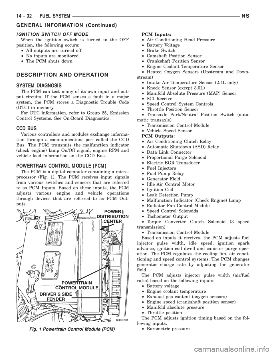
processor (Fig. 1). The PCM receives input signals
from various switches and sensors that are referred
to as PCM Inputs. Based on these inputs, the PCM
adjusts various engine and vehicle operations
through devices that are referred to as PCM Out-
puts.PCM Inputs:
²Air Conditioning Head Pressure
²Battery Voltage
²Brake Switch
²Camshaft Position Sensor
²Crankshaft Position Sensor
²Engine Coolant Temperature Sensor
²Heated Oxygen Sensors (Upstream and Down-
stream)
²Intake Air Temperature Sensor (2.4L only)
²Knock Sensor (execpt 3.0L)
²Manifold Absolute Pressure (MAP) Sensor
²SCI Receive
²Speed Control System Controls
²Throttle Position Sensor
²Transaxle Park/Neutral Position Switch (auto-
matic transaxle)
²Transmission Control Module
²Vehicle Speed Sensor
PCM Outputs:
²Air Conditioning Clutch Relay
²Automatic Shutdown (ASD) Relay
²Data Link Connector
²Proportional Purge Solenoid
²Electric EGR Transducer
²Fuel Injectors
²Fuel Pump Relay
²Generator Field
²Idle Air Control Motor
²Ignition Coil
²Leak Detection Pump
²Malfunction Indicator (Check Engine) Lamp
²Radiator Fan Control Module
²Speed Control Solenoids
²Tachometer Output
²Torque Converter Clutch Solenoid (3 speed
transmission)
²Transmission Control Module
Based on inputs it receives, the PCM adjusts fuel
injector pulse width, idle speed, ignition spark
advance, ignition coil dwell and canister purge oper-
ation. The PCM regulates the cooling fan, air condi-
tioning and speed control systems. The PCM changes
generator charge rate by adjusting the generator
field.
The PCM adjusts injector pulse width (air/fuel
ratio) based on the following inputs:
²Battery voltage
²Engine coolant temperature
²Exhaust gas content (oxygen sensors)
²Engine speed (crankshaft position sensor)
²Manifold absolute pressure
²Throttle position
The PCM adjusts ignition timing based on the fol-
lowing inputs.
²Barometric pressure
Fig. 1 Powertrain Control Module (PCM)
14 - 32 FUEL SYSTEMNS
GENERAL INFORMATION (Continued)
Page 1330 of 1938
The crankshaft position sensor is located in the
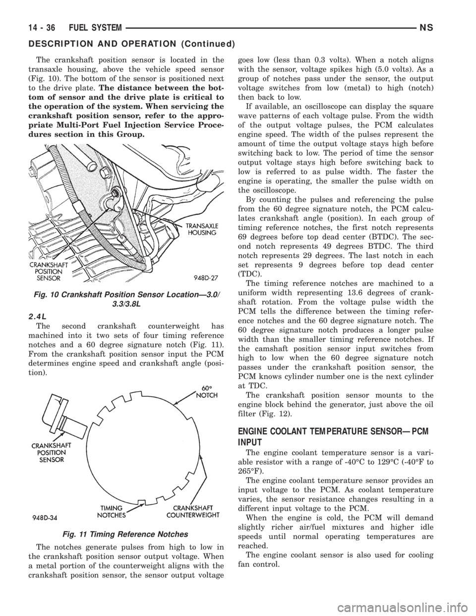
transaxle housing, above the vehicle speed sensor
(Fig. 10). The bottom of the sensor is positioned next
to the drive plate.The distance between the bot-
tom of sensor and the drive plate is critical to
the operation of the system. When servicing the
crankshaft position sensor, refer to the appro-
priate Multi-Port Fuel Injection Service Proce-
dures section in this Group.
2.4L
The second crankshaft counterweight has
machined into it two sets of four timing reference
notches and a 60 degree signature notch (Fig. 11).
From the crankshaft position sensor input the PCM
determines engine speed and crankshaft angle (posi-
tion).
The notches generate pulses from high to low in
the crankshaft position sensor output voltage. When
a metal portion of the counterweight aligns with the
crankshaft position sensor, the sensor output voltagegoes low (less than 0.3 volts). When a notch aligns
with the sensor, voltage spikes high (5.0 volts). As a
group of notches pass under the sensor, the output
voltage switches from low (metal) to high (notch)
then back to low.
If available, an oscilloscope can display the square
wave patterns of each voltage pulse. From the width
of the output voltage pulses, the PCM calculates
engine speed. The width of the pulses represent the
amount of time the output voltage stays high before
switching back to low. The period of time the sensor
output voltage stays high before switching back to
low is referred to as pulse width. The faster the
engine is operating, the smaller the pulse width on
the oscilloscope.
By counting the pulses and referencing the pulse
from the 60 degree signature notch, the PCM calcu-
lates crankshaft angle (position). In each group of
timing reference notches, the first notch represents
69 degrees before top dead center (BTDC). The sec-
ond notch represents 49 degrees BTDC. The third
notch represents 29 degrees. The last notch in each
set represents 9 degrees before top dead center
(TDC).
The timing reference notches are machined to a
uniform width representing 13.6 degrees of crank-
shaft rotation. From the voltage pulse width the
PCM tells the difference between the timing refer-
ence notches and the 60 degree signature notch. The
60 degree signature notch produces a longer pulse
width than the smaller timing reference notches. If
the camshaft position sensor input switches from
high to low when the 60 degree signature notch
passes under the crankshaft position sensor, the
PCM knows cylinder number one is the next cylinder
at TDC.
The crankshaft position sensor mounts to the
engine block behind the generator, just above the oil
filter (Fig. 12).
ENGINE COOLANT TEMPERATURE SENSORÐPCM
INPUT
The engine coolant temperature sensor is a vari-
able resistor with a range of -40ÉC to 129ÉC (-40ÉF to
265ÉF).
The engine coolant temperature sensor provides an
input voltage to the PCM. As coolant temperature
varies, the sensor resistance changes resulting in a
different input voltage to the PCM.
When the engine is cold, the PCM will demand
slightly richer air/fuel mixtures and higher idle
speeds until normal operating temperatures are
reached.
The engine coolant sensor is also used for cooling
fan control.
Fig. 10 Crankshaft Position Sensor LocationÐ3.0/
3.3/3.8L
Fig. 11 Timing Reference Notches
14 - 36 FUEL SYSTEMNS
DESCRIPTION AND OPERATION (Continued)
Page 1356 of 1938
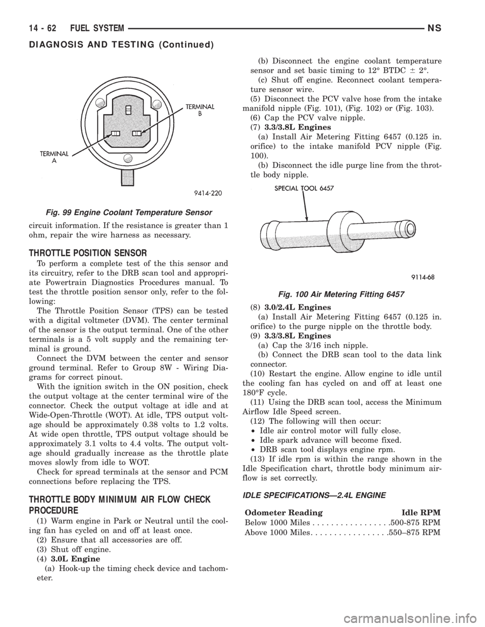
circuit information. If the resistance is greater than 1
ohm, repair the wire harness as necessary.
THROTTLE POSITION SENSOR
To perform a complete test of the this sensor and
its circuitry, refer to the DRB scan tool and appropri-
ate Powertrain Diagnostics Procedures manual. To
test the throttle position sensor only, refer to the fol-
lowing:
The Throttle Position Sensor (TPS) can be tested
with a digital voltmeter (DVM). The center terminal
of the sensor is the output terminal. One of the other
terminals is a 5 volt supply and the remaining ter-
minal is ground.
Connect the DVM between the center and sensor
ground terminal. Refer to Group 8W - Wiring Dia-
grams for correct pinout.
With the ignition switch in the ON position, check
the output voltage at the center terminal wire of the
connector. Check the output voltage at idle and at
Wide-Open-Throttle (WOT). At idle, TPS output volt-
age should be approximately 0.38 volts to 1.2 volts.
At wide open throttle, TPS output voltage should be
approximately 3.1 volts to 4.4 volts. The output volt-
age should gradually increase as the throttle plate
moves slowly from idle to WOT.
Check for spread terminals at the sensor and PCM
connections before replacing the TPS.
THROTTLE BODY MINIMUM AIR FLOW CHECK
PROCEDURE
(1) Warm engine in Park or Neutral until the cool-
ing fan has cycled on and off at least once.
(2) Ensure that all accessories are off.
(3) Shut off engine.
(4)3.0L Engine
(a) Hook-up the timing check device and tachom-
eter.(b) Disconnect the engine coolant temperature
sensor and set basic timing to 12É BTDC62É.
(c) Shut off engine. Reconnect coolant tempera-
ture sensor wire.
(5) Disconnect the PCV valve hose from the intake
manifold nipple (Fig. 101), (Fig. 102) or (Fig. 103).
(6) Cap the PCV valve nipple.
(7)3.3/3.8L Engines
(a) Install Air Metering Fitting 6457 (0.125 in.
orifice) to the intake manifold PCV nipple (Fig.
100).
(b) Disconnect the idle purge line from the throt-
tle body nipple.
(8)3.0/2.4L Engines
(a) Install Air Metering Fitting 6457 (0.125 in.
orifice) to the purge nipple on the throttle body.
(9)3.3/3.8L Engines
(a) Cap the 3/16 inch nipple.
(b) Connect the DRB scan tool to the data link
connector.
(10) Restart the engine. Allow engine to idle until
the cooling fan has cycled on and off at least one
180ÉF cycle.
(11) Using the DRB scan tool, access the Minimum
Airflow Idle Speed screen.
(12) The following will then occur:
²Idle air control motor will fully close.
²Idle spark advance will become fixed.
²DRB scan tool displays engine rpm.
(13) If idle rpm is within the range shown in the
Idle Specification chart, throttle body minimum air-
flow is set correctly.
IDLE SPECIFICATIONSÐ2.4L ENGINE
Odometer Reading Idle RPM
Below 1000 Miles.................500-875 RPM
Above 1000 Miles.................550±875 RPM
Fig. 99 Engine Coolant Temperature Sensor
Fig. 100 Air Metering Fitting 6457
14 - 62 FUEL SYSTEMNS
DIAGNOSIS AND TESTING (Continued)
Page 1364 of 1938
(5) When the sensor is removed, the exhaust man-
ifold threads must be cleaned with an 18 mm X 1.5 +
6E tap. If using original sensor, coat the threads with
Loctite 771-64 anti-seize compound or equivalent.
INSTALLATION
(1) Reverse removal procedure to install a new
sensor.
New sensors are packaged with compound on the
threads and no additional compound is required. The
sensor must be tightened to 27 N´m (20 ft. lbs.)
torque.
KNOCK SENSOR
For removal/installation procedures refer to Group
8D- Ignition System, Service Procedures.
AIR CLEANER ELEMENT
REMOVAL
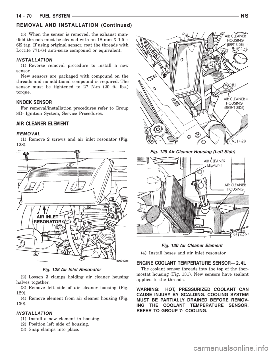
(1) Remove 2 screws and air inlet resonator (Fig.
128).
(2) Loosen 3 clamps holding air cleaner housing
halves together.
(3) Remove left side of air cleaner housing (Fig.
129).
(4) Remove element from air cleaner housing (Fig.
130).
INSTALLATION
(1) Install a new element in housing.
(2) Position left side of housing.
(3) Snap clamps into place.(4) Install hoses and air inlet resonator.
ENGINE COOLANT TEMPERATURE SENSORÐ2.4L
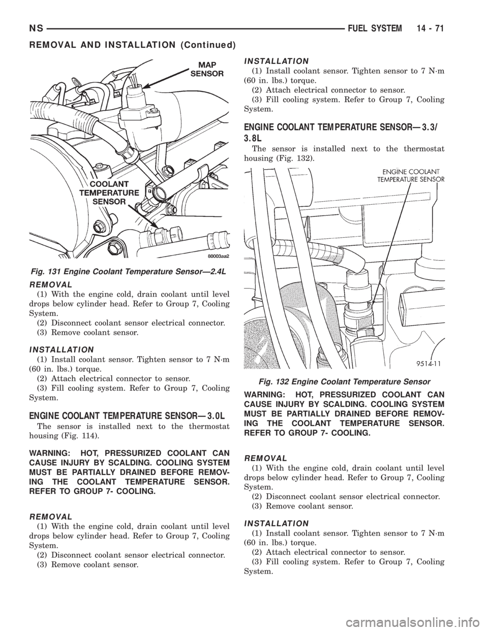
The coolant sensor threads into the top of the ther-
mostat housing (Fig. 131). New sensors have sealant
applied to the threads.
WARNING: HOT, PRESSURIZED COOLANT CAN
CAUSE INJURY BY SCALDING. COOLING SYSTEM
MUST BE PARTIALLY DRAINED BEFORE REMOV-
ING THE COOLANT TEMPERATURE SENSOR.
REFER TO GROUP 7- COOLING.Fig. 128 Air Inlet Resonator
Fig. 129 Air Cleaner Housing (Left Side)
Fig. 130 Air Cleaner Element
14 - 70 FUEL SYSTEMNS
REMOVAL AND INSTALLATION (Continued)
Page 1365 of 1938
REMOVAL
(1) With the engine cold, drain coolant until level
drops below cylinder head. Refer to Group 7, Cooling
System.
(2) Disconnect coolant sensor electrical connector.
(3) Remove coolant sensor.
INSTALLATION
(1) Install coolant sensor. Tighten sensor to 7 N´m
(60 in. lbs.) torque.
(2) Attach electrical connector to sensor.
(3) Fill cooling system. Refer to Group 7, Cooling
System.
ENGINE COOLANT TEMPERATURE SENSORÐ3.0L
The sensor is installed next to the thermostat
housing (Fig. 114).
WARNING: HOT, PRESSURIZED COOLANT CAN
CAUSE INJURY BY SCALDING. COOLING SYSTEM
MUST BE PARTIALLY DRAINED BEFORE REMOV-
ING THE COOLANT TEMPERATURE SENSOR.
REFER TO GROUP 7- COOLING.
REMOVAL
(1) With the engine cold, drain coolant until level
drops below cylinder head. Refer to Group 7, Cooling
System.
(2) Disconnect coolant sensor electrical connector.
(3) Remove coolant sensor.
INSTALLATION
(1) Install coolant sensor. Tighten sensor to 7 N´m
(60 in. lbs.) torque.
(2) Attach electrical connector to sensor.
(3) Fill cooling system. Refer to Group 7, Cooling
System.
ENGINE COOLANT TEMPERATURE SENSORÐ3.3/
3.8L
The sensor is installed next to the thermostat
housing (Fig. 132).
WARNING: HOT, PRESSURIZED COOLANT CAN
CAUSE INJURY BY SCALDING. COOLING SYSTEM
MUST BE PARTIALLY DRAINED BEFORE REMOV-
ING THE COOLANT TEMPERATURE SENSOR.
REFER TO GROUP 7- COOLING.
REMOVAL
(1) With the engine cold, drain coolant until level
drops below cylinder head. Refer to Group 7, Cooling
System.
(2) Disconnect coolant sensor electrical connector.
(3) Remove coolant sensor.
INSTALLATION
(1) Install coolant sensor. Tighten sensor to 7 N´m
(60 in. lbs.) torque.
(2) Attach electrical connector to sensor.
(3) Fill cooling system. Refer to Group 7, Cooling
System.
Fig. 131 Engine Coolant Temperature SensorÐ2.4L
Fig. 132 Engine Coolant Temperature Sensor
NSFUEL SYSTEM 14 - 71
REMOVAL AND INSTALLATION (Continued)