Page 1562 of 1938
VALVE BODY
REMOVAL
NOTE: To ease removal of the valve body, turn the
manual valve lever fully clockwise.
Fig. 26 Transaxle Control Module
Fig. 27 Remove Oil Pan Bolts
Fig. 28 Remove Oil Pan
Fig. 29 Remove Oil Filter
Fig. 30 Remove Valve Body Attaching Bolts
Fig. 31 Push Park Rod Rollers from Guide Bracket
21 - 88 TRANSAXLE AND POWER TRANSFER UNITNS
REMOVAL AND INSTALLATION (Continued)
Page 1563 of 1938

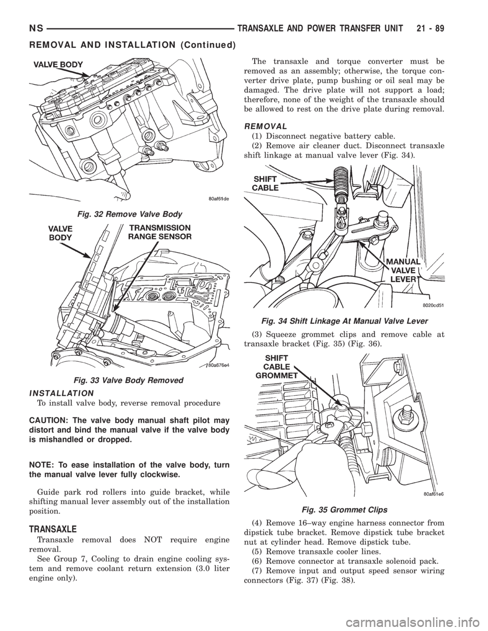
INSTALLATION
To install valve body, reverse removal procedure
CAUTION: The valve body manual shaft pilot may
distort and bind the manual valve if the valve body
is mishandled or dropped.
NOTE: To ease installation of the valve body, turn
the manual valve lever fully clockwise.
Guide park rod rollers into guide bracket, while
shifting manual lever assembly out of the installation
position.
TRANSAXLE
Transaxle removal does NOT require engine
removal.
See Group 7, Cooling to drain engine cooling sys-
tem and remove coolant return extension (3.0 liter
engine only).The transaxle and torque converter must be
removed as an assembly; otherwise, the torque con-
verter drive plate, pump bushing or oil seal may be
damaged. The drive plate will not support a load;
therefore, none of the weight of the transaxle should
be allowed to rest on the drive plate during removal.
REMOVAL
(1) Disconnect negative battery cable.
(2) Remove air cleaner duct. Disconnect transaxle
shift linkage at manual valve lever (Fig. 34).
(3) Squeeze grommet clips and remove cable at
transaxle bracket (Fig. 35) (Fig. 36).
(4) Remove 16±way engine harness connector from
dipstick tube bracket. Remove dipstick tube bracket
nut at cylinder head. Remove dipstick tube.
(5) Remove transaxle cooler lines.
(6) Remove connector at transaxle solenoid pack.
(7) Remove input and output speed sensor wiring
connectors (Fig. 37) (Fig. 38).
Fig. 32 Remove Valve Body
Fig. 33 Valve Body Removed
Fig. 34 Shift Linkage At Manual Valve Lever
Fig. 35 Grommet Clips
NSTRANSAXLE AND POWER TRANSFER UNIT 21 - 89
REMOVAL AND INSTALLATION (Continued)
Page 1565 of 1938

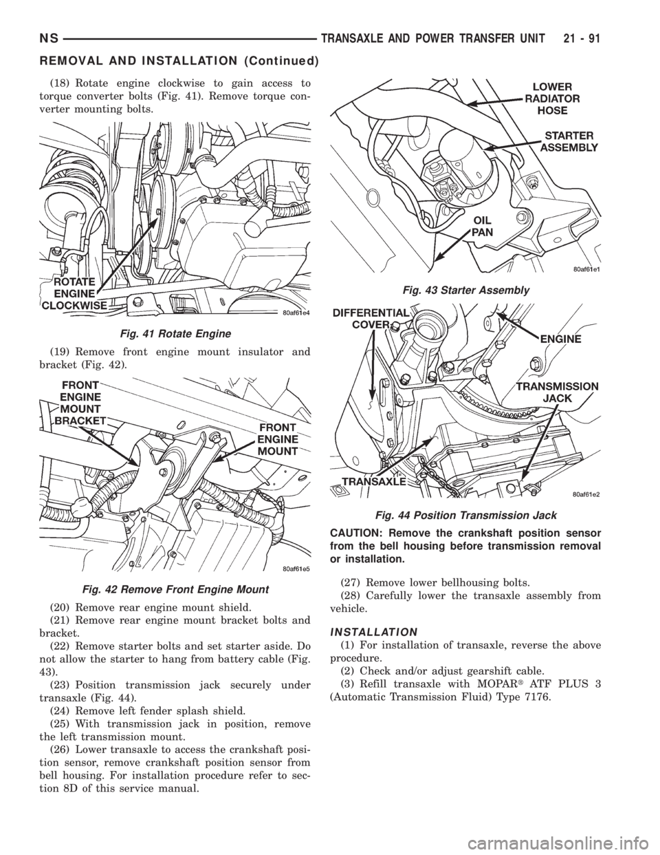
(18) Rotate engine clockwise to gain access to
torque converter bolts (Fig. 41). Remove torque con-
verter mounting bolts.
(19) Remove front engine mount insulator and
bracket (Fig. 42).
(20) Remove rear engine mount shield.
(21) Remove rear engine mount bracket bolts and
bracket.
(22) Remove starter bolts and set starter aside. Do
not allow the starter to hang from battery cable (Fig.
43).
(23) Position transmission jack securely under
transaxle (Fig. 44).
(24) Remove left fender splash shield.
(25) With transmission jack in position, remove
the left transmission mount.
(26) Lower transaxle to access the crankshaft posi-
tion sensor, remove crankshaft position sensor from
bell housing. For installation procedure refer to sec-
tion 8D of this service manual.CAUTION: Remove the crankshaft position sensor
from the bell housing before transmission removal
or installation.
(27) Remove lower bellhousing bolts.
(28) Carefully lower the transaxle assembly from
vehicle.
INSTALLATION
(1) For installation of transaxle, reverse the above
procedure.
(2) Check and/or adjust gearshift cable.
(3) Refill transaxle with MOPARtATF PLUS 3
(Automatic Transmission Fluid) Type 7176.
Fig. 41 Rotate Engine
Fig. 42 Remove Front Engine Mount
Fig. 43 Starter Assembly
Fig. 44 Position Transmission Jack
NSTRANSAXLE AND POWER TRANSFER UNIT 21 - 91
REMOVAL AND INSTALLATION (Continued)
Page 1570 of 1938
NOTE: To ease removal of the valve body, turn the
manual valve fully clockwise.
CAUTION: Do not handle the valve body from the
manual valve. Damage could result.
Fig. 63 Remove Valve Body Attaching Bolts
Fig. 64 Push Park Rod Rollers from Guide Bracket
Fig. 65 Remove Valve Body
Fig. 66 Valve Body Removed
Fig. 67 Remove Accumulators
21 - 96 TRANSAXLE AND POWER TRANSFER UNITNS
DISASSEMBLY AND ASSEMBLY (Continued)
Page 1602 of 1938
Fig. 231 Install Strap Bolts
Fig. 232 Turn Stirrup Clockwise Against Flats Of
Output Gear Retaining Bolt
Fig. 233 Tighten Stirrup Strap Bolts To 23 N´m
(200 in. lbs.)
Fig. 234 Bend Tabs On Strap Up Against Flats Of
Bolts
Fig. 235 Install Transfer Shaft Bearing Cone
Fig. 236 Install Bearing Cup To Shaft
21 - 128 TRANSAXLE AND POWER TRANSFER UNITNS
DISASSEMBLY AND ASSEMBLY (Continued)
Page 1611 of 1938
NOTE: Dependent on engine application, some
accumulators will have two springs and others will
have one spring. The springs are color coded for
application and year.NOTE: To ease installation of the valve body, turn
the manual valve fully clockwise.
Fig. 271 Install Oil Pump
Fig. 272 Install Pump Attaching Bolts
Fig. 273 Install Low/Reverse Accumulator
Fig. 274 Install Low/Reverse Accumulator Plug
(Cover)
Fig. 275 Install Low/Reverse Accumulator Snap
Ring
Fig. 276 Accumulator (Underdrive)
NSTRANSAXLE AND POWER TRANSFER UNIT 21 - 137
DISASSEMBLY AND ASSEMBLY (Continued)
Page 1699 of 1938

INSTALLATION
(1) Assemble the differential side gears, pinion
gears and pinion gears with the pinion gear washers.
(2) Install pinion shaft retaining pin (Fig. 172).
(3) Stake pinion shaft retaining pin with a suitable
chisel (Fig. 173).
(4) Rotate the assembly two full revolutions both
clockwise and counterclockwise. Set up dial indicator
as shown and record end play (Fig. 174) (Fig. 175).
Rotate side gear 90 degrees and record another end
play. Again, rotate side gear 90 degrees and record a
final end play.(5) Using the smallest end play recorded, shim
that side gear to within .02540 mm to .3302 mm
(0.001 to 0.013 inch). The other side gear should be
checked using the same procedure.
CAUTION: Side gear end play must be within 02540
mm to .3302 mm (0.001 to 0.013 inch). Five select
thrust washers are available: 0.027, 0.032, 0.037,
0.042, and 0.047 inch.
SYNCHRONIZER
The 1±2 synchronizer is a dual-cone synchronizer
(Fig. 176). The disassembly and assembly procedures
are the same as the 3±4 synchronizer (Fig. 177)
Fig. 171 Differential Gears
Fig. 170 Remove Pinion Gears, Side Gears, and
Thrust Washers by Rotating Side Gears to Opening
in CaseFig. 172 Install Retaining Pin
NS/GSA±598 MANUAL TRANSAXLE 21 - 43
DISASSEMBLY AND ASSEMBLY (Continued)
Page 1749 of 1938

INSTALLATION
(1) Place heated seat module in position on seat
pan.
(2) Install module attaching screws.
(3) Connect module wire connectors.
(4) Install seat.
HEATED SEAT SWITCH
Diagnostic information for heated seat switch is
located in Group 8R, Power Seats.
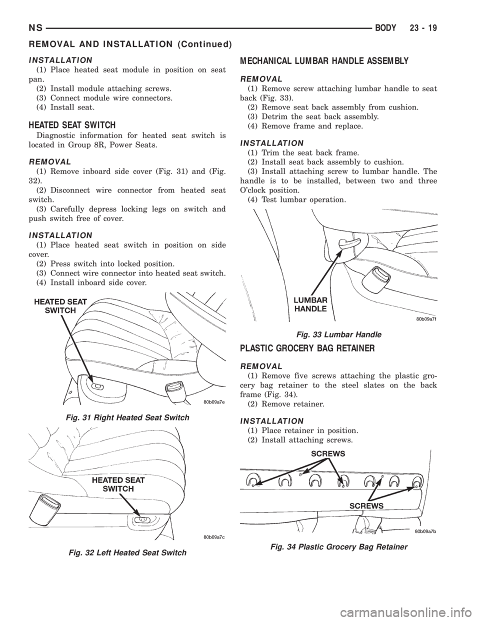
REMOVAL
(1) Remove inboard side cover (Fig. 31) and (Fig.
32).
(2) Disconnect wire connector from heated seat
switch.
(3) Carefully depress locking legs on switch and
push switch free of cover.
INSTALLATION
(1) Place heated seat switch in position on side
cover.
(2) Press switch into locked position.
(3) Connect wire connector into heated seat switch.
(4) Install inboard side cover.
MECHANICAL LUMBAR HANDLE ASSEMBLY
REMOVAL
(1) Remove screw attaching lumbar handle to seat
back (Fig. 33).
(2) Remove seat back assembly from cushion.
(3) Detrim the seat back assembly.
(4) Remove frame and replace.
INSTALLATION
(1) Trim the seat back frame.
(2) Install seat back assembly to cushion.
(3) Install attaching screw to lumbar handle. The
handle is to be installed, between two and three
O'clock position.
(4) Test lumbar operation.
PLASTIC GROCERY BAG RETAINER
REMOVAL
(1) Remove five screws attaching the plastic gro-
cery bag retainer to the steel slates on the back
frame (Fig. 34).
(2) Remove retainer.
INSTALLATION
(1) Place retainer in position.
(2) Install attaching screws.
Fig. 31 Right Heated Seat Switch
Fig. 32 Left Heated Seat Switch
Fig. 33 Lumbar Handle
Fig. 34 Plastic Grocery Bag Retainer
NSBODY 23 - 19
REMOVAL AND INSTALLATION (Continued)