Page 9 of 30
. The function of the transpon-
de")
9
EWS
System Components
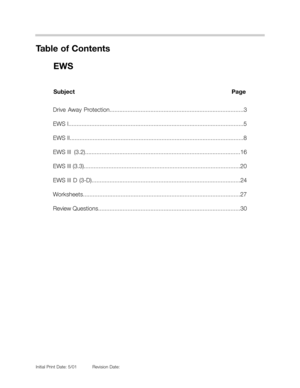
Key with Transponder
Four keys are initially supplied with each vehicle.
Each key contains a wireless electronic chip
(transponder chip). The function of the transpon-
der is to receive and transmit data to the EWS II
control module. The transponder contains a
wireless read/write EEPROM in addition to a
small capacitor and coil for self power capabili-
ties.
The functions of the EEPROM are:
• Store codes for key identification, password and changing codes.
• Receive and respond to coded messages from the EWS II control module.
Power for the transponder is produced through the inductive coil and stored in the capac-
itor. Each time the key is inserted into the ignition AC voltage in the antenna ring induces
voltage in the inductive coil.
All keys either with remote or without, includ-
ing wallet and valet keys contain transponders.
8510108
8510107
Key Notes:
Keys have temperature oper-
ating range of -40
0to 800C.
Keys are shock resistant from
a height of 10 meters.
Inductive coil
Capacitor
Read/Write
EEPROM
Page 10 of 30
 betwe")
10
EWS
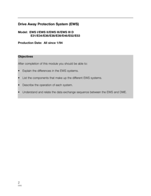
Ring Antenna
The Ring Antenna is an inductive coil installed around the lock cylinder which provides
power for the transponder in the key and the communication link (antenna) between the key
and the transmit/receive module.
Transmitter/Receiver Module
The Transmitter/Receiver module supplies power to the transponder through the ring
antenna and controls the flow of data between the transponder and the EWS II control
module.
Data transmission between the transmitter/receiver module and the transponder takes
place over a radio frequency of 125 KHz amplitude modulated AM signal.
The transmitter/receiver module converts the
analog data received through the AM signal to
digital data and transfers it to the EWS II control
module over a single wire bi-directional data
interface.
8510109
8510110
Workshop Hint:
On E34 and E36 models the transmitter/receiver mod-
ule is located under the dash near the steering column.
On E 31, E38 and E39 models the transmitter/receiver
module is located in the steering column cover on the
right hand side of the column.
Inductive
coil
Ring Antenna
Transmitter
Receiver
Module
Transmitter/Receiver Module under Dash
Connector
to EWS II
Module
Ring Antenna
fits around the
Lock Cylinder
Page 11 of 30

11
EWS
EWS II Control Module
The EWS II Control Module is linked to the BC, GM, DME, Trans Range switch and the
starter for drive away protection operation. The module incorporates an integral starter relay
and stores data and codes for communication with the transponder chip.
The function of the EWS II module is to provide improved drive away protection for the vehi-
cle and it incorporates many features of previous systems:
• Lock out of the starter when the code function of the BC is set.
• Disable injection and ignition through the DME.
• Prevent starter engagement with engine running.
• Recognition of Park/Neutral position with automatic transmission.
New features that have been added:
• Disable injection, ignition and starter operation until a correct key is recognized.
• EWS and DME synchronization through the use of the ISN.
• Release of double lock when a correctly coded key is switched on.
The EWS II control module stores the following data
for the key transponder inter-link:
• Key identification code- up to 10 keys.
• Key password.
• Changing code- up to 10 keys.
Workshop Hint:
On E31, E36, E38 and E39 models the
EWS II control module is located behind
the glove box in the electrical carrier.
On E34 models the module is located on
the drivers side of the vehicle behind the
knee bolster.
8510106
Typical component locations
E36 shown
Page 12 of 30

12
EWS
DME
The DME is redesigned to incorporate the new ISN code. As of production 1/95 all DME
control modules will contain the unique ISN number and will not interchange with previous
DME’s. The following new features are added to the DME:
• Unique ISN assigned to DME during manufacture, it can not be changed, altered or
overwritten.
• The BC code input to the DME is eliminated.
• The DME and EWS II control module must be synchronized. The DME sends the ISN to
the EWS II module which stores the number for replay to the DME.
• The ISN received from the EWS II module during start-up is compared to the internal
ISN of the DME. The numbers must match before the start operation is allowed to con-
tinue.
• The ISN is sent to the DME continuously by the EWS II module with the key on.
• The DME will ignore loss of the ISN after the engine is running.
• The DME retains the ISN information from the EWS II module for 10 seconds after the
ignition is switched off.
Restarting or switching the ignition on within the 10 seconds cancels the key
identification process.
Workshop Hints:
The DME is located in the E-Box.
Remember the EWS-DME link stays active for 10
seconds while testing keys for proper operation.
65101108
Page 13 of 30

13
EWS
Principle of Operation
The starting sequence involves communication between all the components of the system.
Any break-down in the communication process will result in a no start condition. The
sequence of events for vehicle starting is as follows:
• The key is inserted into the lock cylinder and switched “ON”. The transmitter/receiver
module is powered through KL R. The transmitter/receiver module sends a 125kHz.
AM signal to the ring antenna. The AM signal induces voltage in the key coil and pow-
ers up the transponder.
• Powered up, the key transponder sends the key identification code to the transmitter/
receiver module via the 125kHz AM signal (1). The transmitter/receiver module converts
the AM signal to a digital signal and sends it to the EWS II control module (2).
• The EWS II control module verifies the key identification code and checks to see if the
key is enabled (3).
• Upon accepting the key as valid and enabled the EWS II control module sends a digital
password (4) to the transmitter/receiver module, which converts the data to an AM
signal (5) and sends it to the transponder via the ring antenna (6).
8510120
8510121
Transmitter
Receiver
Module
Transmitter
Receiver
Module
Transponder
Chip in Key
Transponder
Chip in Key
EWS II
EWS II
Page 14 of 30
 to the transmitter/receiver module which converts this AM signal to
digital (8) and sends")
14
EWS
• If the transponder accepts the password as correct the transponder releases the
changing code (7) to the transmitter/receiver module which converts this AM signal to
digital (8) and sends it to the EWS II module (9).
• If the changing code received by the EWS II module is correct, the status of the BC,
transmission range switch and TD is examined. With correct input status the internal
starter relay is energized and the starter motor begins to operate (10). At the same
time the EWS II module sends the ISN to the DME via the single wire communication
link (11).
• If the ISN code stored in the EWS II module matches that of the DME, the drive away
protection is cancelled and injection and ignition is enabled.
• During the process of sending the ISN to the DME, the EWS II module sends a new
changing code to the transponder through the transmitter/receiver and ring antenna.
The transponder stores the changing code until
the next starting sequence.
8510122
8510124
10
11
Workshop Hints:
The entire process takes place in under 750ms.
If the starter operates, the key has been recognized as
OK and the key requires no further diagnosis. Check
status of ISN in DISplus or MoDic.
Recognition of a valid key by the EWS II module caus-
es it to send an unlock signal to the GM if the vehicle is
in double lock.
Transponder
Chip in KeyTransmitter
Receiver
Module
EWS II
EWS II
Page 15 of 30

15
EWS
Replacement Procedures
Keys
Up to 6 additional keys may be ordered as replacement keys. The EWS II control module
is codeable for only 10 keys (4 delivered with vehicle and 6 replacement).
EWS II Control Module
Replacement EWS II Control Modules must be ordered VIN specific. EWS II modules con-
tain the VIN and coding from the factory to recognize the key codes. Modules from other
vehicles will not recognize keys as being valid and not start the engine.
EWS II Control Modules store the Central Coding Key (ZCS) and the VIN. If the EWS II con-
trol module is replaced the system must be ZCS coded (SIB 61 02 96 and TRI 61 01 95).
The EWS II module must be synchronized with the DME (aligned). There is no limit to the
number of times the ISN may be changed in the EWS II module.
DME Control Module
The DME Control Module is not ordered VIN specific and must be programmed during
replacement. The ISN from the new DME must
be transferred to the EWS II module using the
DISplus or MoDic.
Key Activation
Keys that are lost or stolen may be deactivated
or made to not operate the starter functions.
The SERVICE FUNCTIONS of the DISplus or
MoDic for EWS II contains a “Bar/Release
Code” function that activates and deactivates
keys of the EWS II. Any key may be “Barred”
except the key in the ignition at the time of
deactivation. The lost or stolen key can be iden-
tified by the identification of the remaining keys.
There is no limit to the number of times a key
can be activated/deactivated.
EWS II Update
Beginning MY 1997 E31 and E36 vehicles with manual transmissions were updated to include a clutch
pedal position switch. The clutch switch signal is provided by a hall-effect sensor providing a high sig-
nal when the clutch is depressed.
Note: A “Barred” key will not start the engine, it
will still unlockthe vehicle.
Page 16 of 30

The 1997 Model Year E38is equipped with EWS III (3.2) drive away protection. E39vehi-
cles produced 3/97and later are also equipped with EWS III (3.2).
Purpose of the System
The m")
16
EWS
EWS III (3.2)
The 1997 Model Year E38is equipped with EWS III (3.2) drive away protection. E39vehi-
cles produced 3/97and later are also equipped with EWS III (3.2).
Purpose of the System
The major changes of the EWS III (3.2) system over the EWS II are a modified control mod-
ule, revised wiring and the addition of the clutch switch input.
Output functions, starter control and ISN signal, remain the same for EWS III (3.2).
Component changes are:
• EWS III (3.2) Control Module.
• Input From The K-Bus.
• Clutch Switch.
• Transmitter/Receiver Module Eliminated.
System Components
EWS III (3.2) Control Module
The EWS III (3.2) Control Module has a 13 pin connector. The transmitter/receiver module
is no longer a separate module of the system with the electronic functions for the data
transfer between the key transponder and the EWS control module being handled directly
by the EWS III (3.2) control module. The vehicle wiring harness has been changed to reflect
this modification and to route the wiring from the ring antenna directly to the EWS III (3.2)
control module.
Input From The K-Bus
Reduction in wiring has also been accomplished with the use of the K-Bus for data com-
munication between the GM, Door Module, IKE and the EWS III (3.2) control module. This
data link provides the following signals to be communicated on one wire:
• Engine Speed.
• Lock and Unlock Requests.
• Code Function.
• Range Selector Position (Redundant Signal).
Engine Speed
The DME outputs the engine speed “TD” signal over the CAN Bus to the IKE. The IKE uses
the TD information as needed and passes it on to the EWS III (3.2) via the K-Bus.