Page 17 of 25
24-178
Data transfer between Engine Control
Module (ECM) and CAN-bus capable
control modules, checking
Notes:
Data exchange between individual control
modules occurs via a bus system.
The term "CAN-bus" refers to a system that
transports and distributes data.
The wire connections between the control
modules, via which data is transferred, are
referred to as data wires.
Data is transferred to the connected control
modules serially (one after the other) via these
data wires (i.e. engine speed, accelerator
position).
Checking bus system
The DTC table suggested checking the data
exchange between the Engine Control Module
(ECM) and CAN capable control modules.
- Connect VAS5051 tester Page 01
-7 and
select vehicle system "01 - Engine electronics".
Ignition must remain switched on for this.
Pa
ge 17 of 25 Additional si
gnals, checkin
g
11/22/2002 htt
p://127.0.0.1:8080/audi/servlet/Dis
play?action=Goto&t
yp
e=re
pair&id=AUDI.B5.FU07.24.5
Page 18 of 25
24-179
Display on VAS5051:
- Select diagnostic function "08 - Read Measuring Value Block" in
selection -1-.
Display on VAS5051:
Note:
Measuring value blocks 125 and 126 indicate the participants in the
powertrain data-BUS. 1 - Enter display group Max. input value = 255
- Select function "125" in button field -2- for "display group number 125"
and press Q button to confirm input.
Pa
ge 18 of 25 Additional si
gnals, checkin
g
11/22/2002 htt
p://127.0.0.1:8080/audi/servlet/Dis
play?action=Goto&t
yp
e=re
pair&id=AUDI.B5.FU07.24.5
Page 19 of 25
24-180
Display on VAS5051:
- Check indications in display fields -1- through -4-.
CAN capable control modules connected to the Engine Control Module
(ECM) are indicated:
No indication: Control module not CAN-capable
Indication 1: CAN capable control module is connected to databus
Indication 0: CAN capable control module is not connected to
databus
-
Press button to change into display group 126.
- Check under display group 126 in the same manner.
-
Press "08 - erase DTC memory" to end function -button.
Display on VAS5051:
- Select diagnostic function "06 - end output" in selection -1-.
Pa
ge 19 of 25 Additional si
gnals, checkin
g
11/22/2002 htt
p://127.0.0.1:8080/audi/servlet/Dis
play?action=Goto&t
yp
e=re
pair&id=AUDI.B5.FU07.24.5
Page 20 of 25
24-181
Display on VAS5051:
When a control module responds with its identification, the display
indicates the number of stored errors or indicates "no malfunctions
recognized".
DTCs stored in the system are indicated in sequence and printed out.
Then the VAG1551 scan tool sends the next address word.
If a malfunction related to the"powertrain databus" or the "CAN-bus" is
indicated:
If the correct control modules are installed: - In selection -1-, press diagnostic function "00 - Check DTC memory -
complete system".
DTC memory of all OBD capable systems in the vehicle will be
checked.
- Check whether the Engine Control Module (ECM) and other CAN
capable control modules installed are appropriate for this vehicle (part
no. and coding).
- Check to be sure the multi-pin connectors of the control modules are
securely connected.
Pa
ge 20 of 25 Additional si
gnals, checkin
g
11/22/2002 htt
p://127.0.0.1:8080/audi/servlet/Dis
play?action=Goto&t
yp
e=re
pair&id=AUDI.B5.FU07.24.5
Page 21 of 25
24-182
If multi-pin connectors are properly secured:
- Check CAN bus system
Checking a "two-line bus system"
Three or more control modules are
communicating across a "two-line bus
system".
- Analyze the DTCs stored in the memories of the
control modules.
Note:
This analysis will help you locate the cause of the
line malfunction.
Pa
ge 21 of 25 Additional si
gnals, checkin
g
11/22/2002 htt
p://127.0.0.1:8080/audi/servlet/Dis
play?action=Goto&t
yp
e=re
pair&id=AUDI.B5.FU07.24.5
Page 22 of 25
24-183
Example 1:
From the DTCs stored in the memories, you have determined that control
module 1 is not communicating with control modules 2 and 3.
Electrical Wiring Diagrams, Troubleshooting & Component Locations Control module
DTCs stored in DTC memories:
1
Missing signal from control module 2Missing signal from control module 3
2 Missing signal from control module 1
3 Missing signal from control module 1
- Switch ignition off.
- Disconnect the control modules connected across the bus wires and
check the bus wires for an open circuit. - Replace control module 1 if no malfunctions can be found in the bus
wires.
Pa
ge 22 of 25 Additional si
gnals, checkin
g
11/22/2002 htt
p://127.0.0.1:8080/audi/servlet/Dis
play?action=Goto&t
yp
e=re
pair&id=AUDI.B5.FU07.24.5
Page 23 of 25
24-184
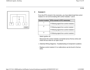
Example 2:
From the DTCs stored in the memories, you have determined that control
module 2 is not communicating with control modules 1 and 3.
Electrical Wiring Diagrams, Troubleshooting & Component Locations Control module
DTCs stored in DTC memories:
1
Missing signal from control module 2
2 Missing signal from control module 1Missing signal from control module 3
3 Missing signal from control module 2
- Switch ignition off.
- Disconnect the control modules connected across the bus wires and
check the bus wires for an open circuit. - Replace control module 2 if no malfunctions can be found in the bus
wires.
Pa
ge 23 of 25 Additional si
gnals, checkin
g
11/22/2002 htt
p://127.0.0.1:8080/audi/servlet/Dis
play?action=Goto&t
yp
e=re
pair&id=AUDI.B5.FU07.24.5
Page 24 of 25
24-185
Example 3:
Using the DTCs stored in the memories, you
have determined that none of the control
modules are sending or receiving signals.
Control
module
DTCs stored in DTC
memories:
1
Powertrain CAN-bus faulty
2 Powertrain CAN-bus faulty
3 Powertrain CAN-bus faulty
- Switch ignition off.
Electrical Wiring Diagrams, Troubleshooting & Component Locations - Disconnect the control modules connected across the bus wires and
check bus wires for a short circuit to B+ and Ground (GND).
Pa
ge 24 of 25 Additional si
gnals, checkin
g
11/22/2002 htt
p://127.0.0.1:8080/audi/servlet/Dis
play?action=Goto&t
yp
e=re
pair&id=AUDI.B5.FU07.24.5


 and CAN-bus capable
control modules, checking
Notes:
Data exchange between individual control
modules occurs via a bu")

 are indicated:
No indication")


