Page 17 of 27
34-57
- Pull input shaft ball bearing out of transmission housing.
- Remove circlip (arrow) behind input shaft ball bearing.
- Note thickness of circlip, if ball bearing, drive axle or transmission
housing are not replaced.
Pa
ge 17 of 27 Transmission, disassemblin
g and assemblin
g
11/19/2002 htt
p://127.0.0.1:8080/audi/servlet/Dis
play?action=Goto&t
yp
e=re
pair&id=AUDI.B5.TM02.34.5
Page 18 of 27
34-58
- Remove cover -A- together with Torsen differential from transmission
cover -B-.
- Remove compression spring from drive pinion.
- Remove transmission cover -B- from transmission housing -C-.
- Remove bolts (arrows) and pull out multi-function switch.
Pa
ge 18 of 27 Transmission, disassemblin
g and assemblin
g
11/19/2002 htt
p://127.0.0.1:8080/audi/servlet/Dis
play?action=Goto&t
yp
e=re
pair&id=AUDI.B5.TM02.34.5
Page 19 of 27
34-59
- Remove relay shaft stop bolts (arrows) items 4, 8 Page 34
-51
, and
Page 34
-52
.
- Unbolt shift detent (arrow) and swing it out.
Pa
ge 19 of 27 Transmission, disassemblin
g and assemblin
g
11/19/2002 htt
p://127.0.0.1:8080/audi/servlet/Dis
play?action=Goto&t
yp
e=re
pair&id=AUDI.B5.TM02.34.5
Page 20 of 27
34-60
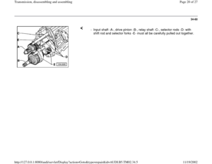
- Input shaft -A-, drive pinion -B-, relay shaft -C-, selector rods -D- with
shift rod and selector forks -E- must all be carefully pulled out together.
Pa
ge 20 of 27 Transmission, disassemblin
g and assemblin
g
11/19/2002 htt
p://127.0.0.1:8080/audi/servlet/Dis
play?action=Goto&t
yp
e=re
pair&id=AUDI.B5.TM02.34.5
Page 21 of 27
34-61
Installing
Note:
If the input shaft ball bearing, the input shaft or
the transmission housing are replaced, it is
necessary to re-determine the thickness of the
circlips for the input shaft first, input shaft,
adjusting Page 35
-17
.
- For easier installation of following components, swing transmission
housing into position shown.
Note:
The relay shaft -C- and the shift rod can also be installed later if
necessary Page 34
-62
, Illustration V34-1816 and Page 34
-63
,
illustration V34-2120 - Assemble input shaft -A-, drive pinion -B-, relay shaft -C-, selector rods
-D- with shift rod and selector forks -E-.
- Install these components into transmission housing as a set.
Pa
ge 21 of 27 Transmission, disassemblin
g and assemblin
g
11/19/2002 htt
p://127.0.0.1:8080/audi/servlet/Dis
play?action=Goto&t
yp
e=re
pair&id=AUDI.B5.TM02.34.5
Page 22 of 27
34-62
Position of shift mechanism in transmission.
Note:
Illustration is shown without the drive axle and pinion. 1 - Shift fork 5th and reverse gears
2 - Shift fork 3rd and 4th gears
3 - Shift fork 1st and 2nd gears
4 - Relay shaft
5 - Shift detent
6 - Shift rod
- Move transmission housing and engage 3rd gear (direction of arrow).
Pa
ge 22 of 27 Transmission, disassemblin
g and assemblin
g
11/19/2002 htt
p://127.0.0.1:8080/audi/servlet/Dis
play?action=Goto&t
yp
e=re
pair&id=AUDI.B5.TM02.34.5
Page 23 of 27
34-63
- Install relay shaft -A-.
- Place inner shift rod -B- sideways into mounting hole in transmission
housing and assemble into mounting eye.
- Carefully turn shift rod in direction of arrow.
- Insert shift detent and tighten bolt (arrow) securely.
Pa
ge 23 of 27 Transmission, disassemblin
g and assemblin
g
11/19/2002 htt
p://127.0.0.1:8080/audi/servlet/Dis
play?action=Goto&t
yp
e=re
pair&id=AUDI.B5.TM02.34.5
Page 24 of 27
34-64
- Install relay shaft stop bolts (arrows).
- Replace O-ring for multi-function switch.
- Carefully insert multi-function switch and tighten (arrows).
Pa
ge 24 of 27 Transmission, disassemblin
g and assemblin
g
11/19/2002 htt
p://127.0.0.1:8080/audi/servlet/Dis
play?action=Goto&t
yp
e=re
pair&id=AUDI.B5.TM02.34.5


 behind input shaft ball bearing.
- Note thickness of circlip, if ball bearing, drive axle or")

 items 4, 8 Page 34
-51
, and
Page 34
-52
.
- Unbolt shift detent (arrow) and swing it out.
Pa
ge 19 of 27 Transmission, disassemblin")


.
- Replace O-ring for multi-function switch.
- Carefully insert multi-function switch and tighten (arrows).
Pa
ge 24 of 27 Transmission,")