1996 ACURA RL KA9 check
[x] Cancel search: checkPage 21 of 1954

DTC 83 : VS A Inhibitio n
NOTE: DT C 8 3 ca n als o b e cause d b y installin g th e No . 5 6 (7. 5 A ) fus e in th e under-hoo d fuse/rela y bo x whil e th e engin e is running .
T o pag e 19-248 * whe n th e DT C
3 5 is indicated .
T o pag e 19-250 * whe n th e DT C
3 6 is indicated .
Check fo r a PGM-F I DT C (se e sectio n 11 *).
ProCarManuals.com
Page 22 of 1954

Troubleshooting
DTC 98 : Differen t Mode l
Does th e MI L sta y ON ?
Ar e ther e an y VS A DTC s othe r
tha n DT C 98 ?
Chec k fo r a n ope n in th e IG 2 cir -
cuit :
1. Tur n th e ignitio n switc h OFF .2. Disconnec t th e VS A converte r
uni t 26 P connector .
3. Tur n th e ignitio n switc h O N(ID .4. Measur e th e voltag e betwee nthe VS A converte r uni t 26 Pconnecto r termina l No . 1 0
an d bod y ground .
I s ther e batter y voltage ?
I s th e DT C 9 8 indicated ?
Chec k fo r loos e terminal s o f th e
VS A contro l uni t connector . I f
necessary , substitut e a known -
goo d VS A modulato-contro l unit ,
an d recheck . Perfor
m th e troubleshootin g fo r
th e PGM-F I system .
Troubleshoo t an d repai r th e
caus e o f thos e DTCs , the n
rechec k fo r DT C 98 .
VSA CONVERTE R UNI T 26 P CONNECTO R
IG2 (YEL/BLK )
Repair ope n in th e wir e betwee n
th e under-das h fuse/rela y bo x
an d th e VS A converte r unit .
Replac e th e VS A converte r unit .
Chec
k th e PGM-F I system :
Turn th e ignitio n switc h O N (II) .
ProCarManuals.com
Page 23 of 1954
Steering Angl e Senso r
Neutral Positio n Chec k an d Memorizin g
Check
1. Connec t th e SC S servic e connecto r t o th e servic e chec k connecto r (2P ) locate d unde r th e glov e box .
2 . Tur n th e ignitio n switc h O N (II) . Th e VS A activatio n indicato r come s o n the n goe s off .
3 . Pres s th e VS A of f switc h on e tim e befor e th e VS A activatio n indicato r come s o n again .
4 . Chec k tha t th e VS A activatio n indicato r come s o n whe n th e steerin g whee l i s i n th e straigh t ahea d positio n (neutra l
position) , an d th e indicato r goe s of f whe n th e steerin g whee l turn s t o th e righ t o r lef t mor e tha n 2. 5 degrees .
5 . I f th e VS A activatio n indicato r doe s no t com e o n o r g o off , perfor m th e neutra l positio n memorizin g procedure .
ProCarManuals.com
Page 32 of 1954

Cavity Wire
Test condition
Test: Desired result
Possible cause if result is not obtained
6
5
4
2
3
1
7
YEL/BLK
YEL
PNK/BLU
GRN
RED/WHT
BLK
WHT
Jump to ground
Ignition switch ON (II)
Jump to ground
Jump to ground
Jump to ground
Under all conditions
Under all conditions
The horn should sound.
Check for voltage to ground:
There should be battery voltage.
The trunk should open.
The doors should unlock.
If all doors are closed, the doors
should lock.
Check for continuity to ground:
There should be continuity.
Check for voltage to ground:
There should be battery voltage.
• Blown No. 44 (20 A) fuse in the
under-hood fuse/relay box
• Faulty multiplex control unit
(passenger's)
• Faulty horn
• An open in the wire
• Blown No. 13 (7.5 A) fuse in the
under-dash fuse/relay box
• An open in the wire
• Blown No. 44 (20 A) fuse in the
under-hood fuse/relay box
• Faulty multiplex control unit
(passenger's)
• Faulty trunk lid opener
• An open in the wire
• Blown No. 44 (20 A) fuse in the
under-hood fuse/relay box
• Faulty multiplex control unit
(passenger's)
• An open in the wire
• Blown No. 44 (20 A) fuse in the
under-hood fuse/relay box
• Faulty multiplex control unit
(passenger's)
• An open in the wire
• Poor ground (G602)
• An open in the wire
• Blown No. 44, (20 A) fuse in the
under-hood fuse/relay box
• An open in the wireProCarManuals.com
Page 38 of 1954

Cavity Wir eTest conditio nTest: Desire d resul tPossibl e caus e if resul t i s no t obtaine d
1
8
7
13
1 1
1 5
4
4
1 4
3
12
BL K
GRN/WH T
WHT/BLK
BLU/WH T
YEL/GRN
BLU/OR N
BLU/GRN
BLU/GR N
BLU/ORN
RED
GR N
Unde r al l condition s
Unde r al l condition s
Ignitio n switc h O N (II )
Ignitio n switc h O N (II ) an d
driver' s windo w switc h
UP
Ignitio n switc h O N (II ) an d
driver' s windo w switc h
AUT O U P
Ignitio n switc h O N (II ) an d
driver' s windo w switc h
AUT O DOW N
Ignitio n switc h O N (II ) an d
driver' s windo w switc h
DOWN
Driver' s windo w switc hDOWN
Driver' s windo w switc hOFF
Driver' s windo w switc hOFF
Connec t th e batter ypower t o th e No . 1 2an d No . 3 terminal s
Connec t th e batter y
power t o th e No . 3 an dNo. 1 2 terminal s
Check fo r continuit y t o ground :
Ther e shoul d b e continuity .
Chec k fo r voltag e to ground :
Ther e shoul d b e batter y voltage .
Chec k fo r voltag e to ground :
Ther e shoul d b e batter y voltage .
Chec k fo r voltag e to ground :
Ther e shoul d b e batter y voltage .
Chec k fo r continuit y t o ground :
Ther e shoul d b e continuity .
Chec k fo r continuit y betwee n th e No . 4
an d No . 1 4 terminals :
Ther e shoul d b e continuity .
Chec k fo r continuit y betwee n th e No . 4
an d No . 1 4 terminals :
Ther e shoul d b e continuity .
Chec k th e driver' s windo w motor :
I t shoul d ru n (th e windo w move s
down) .
Chec k th e driver' s windo w motor :
I t shoul d ru n (th e windo w move s up) . •
Poo r groun d (G251 )
• A n ope n in th e wir e
• Blow n No . 4 1 (2 0 A ) fus e in th e under -
hoo d fuse/rela y bo x
• A n ope n in th e wir e
• Blow n No . 1 7 (7. 5 A ) [No . 2 3 (7. 5 A) ] fus e
i n th e under-das h fuse/rela y bo x
• Fault y powe r windo w rela y
• A n ope n in th e wir e
• Fault y powe r windo w maste r switc h
• A n ope n in th e wire
• Fault y powe r windo w maste r switc h
• Poo r groun d (G251 )
• A n ope n in th e wir e
• Fault y powe r windo w maste r switc h
• A n ope n in th e wir e
• Fault y powe r windo w moto r
• A n ope n in th e wir e
Reconnec t th e connecto r t o th e powe r windo w contro l unit .
Cavit y Wir eTest conditio nTest: Desire d resul tPossibl e caus e if resul t i s no t obtaine d
17
9
5
16
GRN/YE L
YEL/BLU
GRN/RE D
YEL/WHT
Ignition switc h O N (II )
Whil e operatin g th e driv -
er' s windo w switc h
Whil e operatin g th e driv -
er' s windo w switc h Chec
k fo r voltag e betwee n th e No . 1 7
an d No . 9 terminals :
Ther e shoul d b e batter y voltage .
Chec k fo r puls e voltag e betwee n th e
No . 5 an d No . 9 terminals :
Ther e shoul d b e puls e voltag e (th e
voltmete r needl e shoul d mov e bac k
an d fort h alternately) .
Chec k fo r puls e voltag e betwee n th e
No . 1 6 an d No . 9 terminals :
Ther e shoul d b e puls e voltag e (th e
voltmete r needl e shoul d mov e bac k
an d fort h alternately) . •
Fault y powe r windo w moto r
• Fault y pulse r
• A n ope n in th e wir e
ProCarManuals.com
Page 39 of 1954
Power Windows
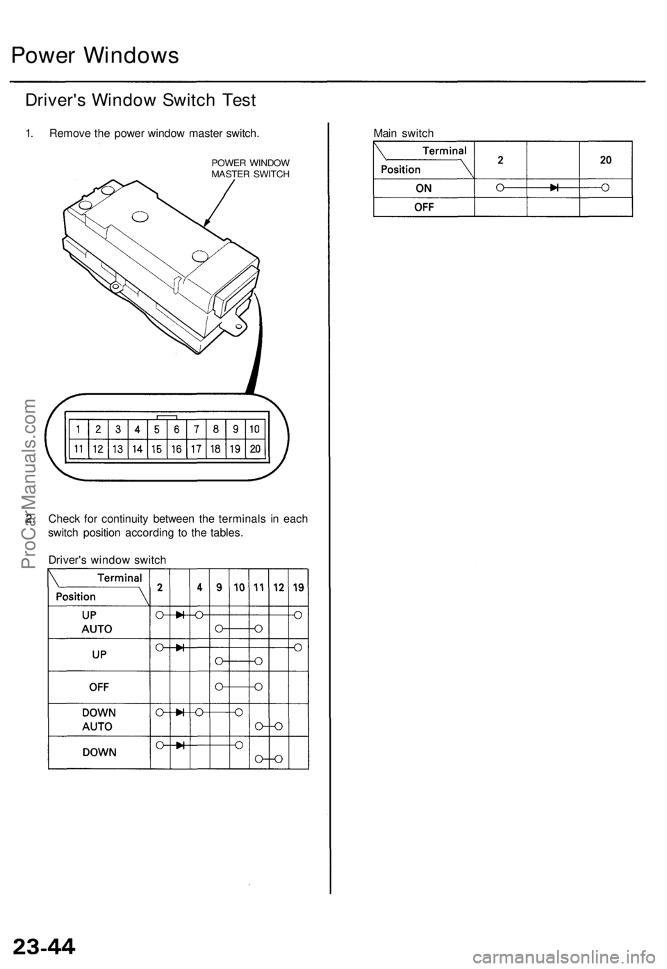
Driver's Window Switch Test
1. Remove the power window master switch.
POWER WINDOW
MASTER SWITCH
2. Check for continuity between the terminals in each
switch position according to the tables.
Driver's window switch
Main switchProCarManuals.com
Page 49 of 1954
OnStar Control Unit Input Test
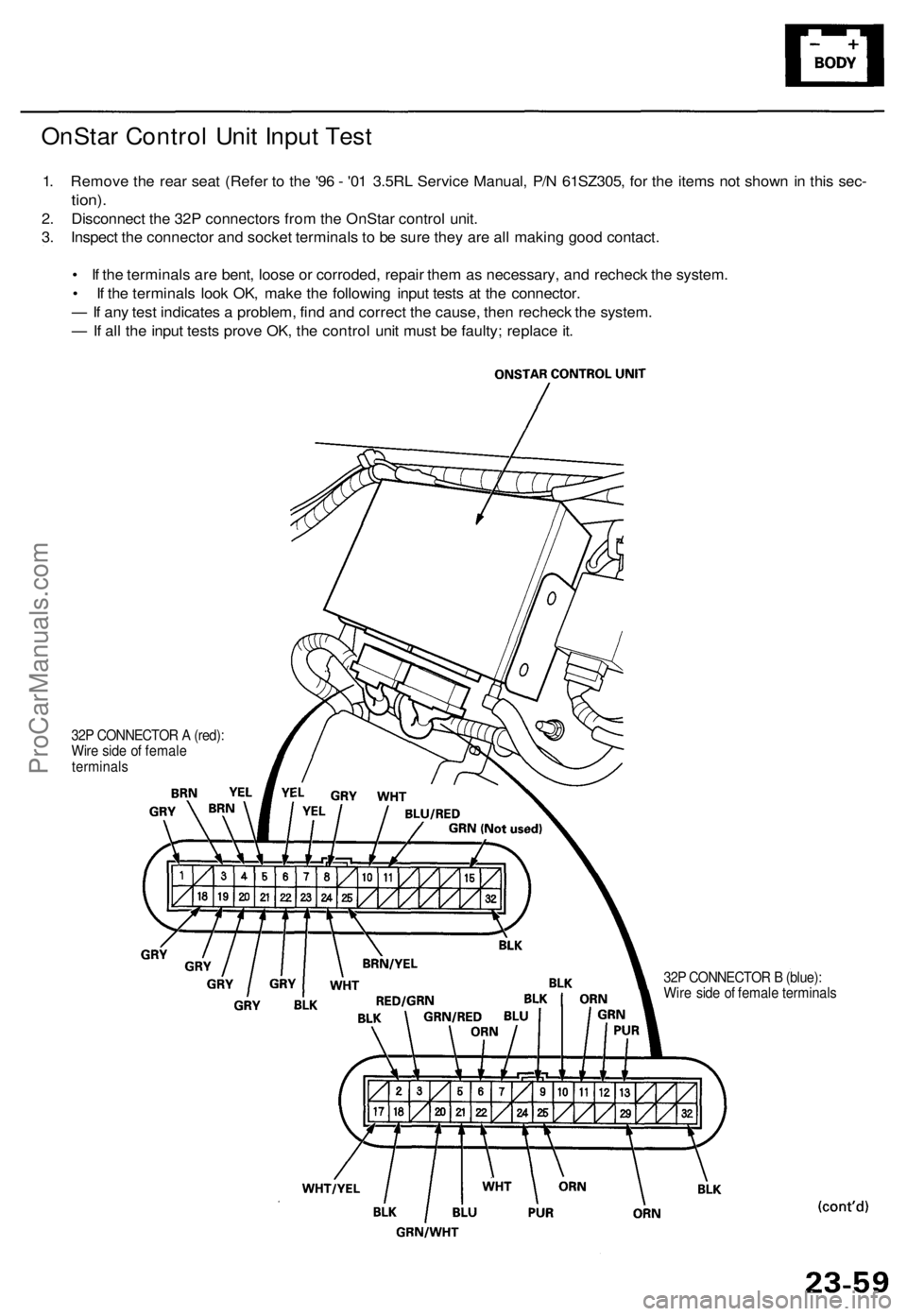
1. Remove the rear seat (Refer to the '96 - '01 3.5RL Service Manual, P/N 61SZ305, for the items not shown in this sec-
tion).
2. Disconnect the 32P connectors from the OnStar control unit.
3. Inspect the connector and socket terminals to be sure they are all making good contact.
• If the terminals are bent, loose or corroded, repair them as necessary, and recheck the system.
• If the terminals look OK, make the following input tests at the connector.
— If any test indicates a problem, find and correct the cause, then recheck the system.
— If all the input tests prove OK, the control unit must be faulty; replace it.
32P CONNECTOR A (red):
Wire side of female
terminals
32P CONNECTOR B (blue):
Wire side of female terminalsProCarManuals.com
Page 50 of 1954

OnStar System ('02 Model USA)
OnStar Control Unit Input Test (cont'd)
Disconnect the connectors from the unit
Cavity Wire Test condition
Test: Desired result
Possible cause if result is not obtained
B17
B22
A32
B6
B3
B2
B9
B18
B32
WHT/YEL
WHT
BLK
ORN
RED/GRN
BLK
Under all conditions
Ignition switch in ACC
(I)
Under all conditions
Under all conditions
Under all conditions
Under all conditions
Check for voltage to ground:
There should be battery voltage.
Check for voltage to ground:
There should be battery voltage.
Check for continuity to ground:
There should be continuity.
Connect to ground:
All horns should sound.
Connect to ground:
The taillights should come on.
Check for continuity to ground:
There should be continuity.
• Blown No. 56 (7.5 A) fuse in the
under-hood fuse/relay box
• An open in the wire
• Blown No. 4 (10 A) fuse in the
under-dash fuse/relay box
• An open in the wire
• Poor ground (G601)
• An open in the wire
• Blown No. 39 (15 A) fuse in the
under-hood fuse/relay box
• Faulty horn relay
• Either horn faulty
• Poor ground (G201)
• An open in the wire
• Blown No. 1 (15 A) fuse in the
under-dash fuse/relay box
• Faulty taillight relay
• Faulty taillight system
• An open in the wire
• An open in the wire
Reconnect the connectors to the unit
Cavity Wire
Test condition
Test: Desired result
Possible cause if result is not obtained
B20
B5
A8
A25
A10
A11
A23
A24
GRN/WHT
GRN/RED
GRY
BRN/YEL
WHT
BLU/RED
BLK
WHT
Front passenger's door
lock key cylinder in neu-
tral position
Front passenger's door
lock key cylinder in
locked position
Front passenger's door
lock key cylinder in neu-
tral position
Front passenger's door
lock key cylinder in
unlocked position
Under all conditions
Under all conditions
OnStar "DOT" button
pushed and human
advisor voice comes
on.
OnStar "DOT" button
pushed and human
advisor voice comes
on.
Under all conditions
Ignition switch in ACC
(I). OnStar "DOT" but-
ton pushed. Speak into
the microphone.
Check for voltage to ground:
There should be battery voltage.
Check for voltage to ground:
There should be less than 1 V.
Check for voltage to ground:
There should be battery voltage.
Check for voltage to ground:
There should be less than 1 V.
Check for continuity to ground:
There should be continuity.
Check for continuity to ground:
There should be continuity.
Check for voltage between the A10
terminal and audio unit C9 or B2
terminal:
There should be 1 V or less.
Check for voltage between the A11
terminal and audio unit C8 or B3
terminal:
There should be 1 V or less.
Check for continuity to ground:
There should be continuity.
Check for voltage to ground:
There should be about 4 V.
• Faulty front passenger's door lock
key cylinder switch
• Poor ground (G401, G402)
• An open in the wire
• Short to ground (if you don't have
5 V when you should)
• An open in the wire
• An open in the wire
• Faulty audio unit
• Faulty speaker
• An open in the wire
• Faulty audio unit
• Faulty speaker
• An open in the wire
• Faulty OnStar buttons and microphone
• An open in the wire
• Faulty OnStar buttons and micro-
phone
• An open in the wireProCarManuals.com