Page 172 of 2248
3) Lift-up the vehicle.
4) Apply SUBARU CRC or its equivalent to threaded por-
tion of front oxygen sensor, and leave it for one minute or
more.
SUBARU CRC (Part No. 004301003)
G2M0411
5) Remove front oxygen sensor.
CAUTION:
When removing oxygen sensor, do not force oxygen
sensor especially when exhaust pipe is cold, other-
wise it will damage exhaust pipe.
G2M0412
B: INSTALLATION
1) Before installing front oxygen sensor, apply anti-seize
compound only to threaded portion of front oxygen sensor
to make the next removal easier.
Anti-seize compound:
SS-30 by JET LUBE
CAUTION:
Never apply anti-seize compound to protector of front
oxygen sensor.
G2M0411
2) Install front oxygen sensor.
Tightening torque:
21±3 N⋅m (2.1±0.3 kg-m, 15.2±2.2 ft-lb)
3) Lower the vehicle.
4) Connect connector of front oxygen sensor.
5) Install air intake duct.
19
2-7SERVICE PROCEDURE
7. Front Oxygen Sensor
Page 173 of 2248
B2M0335
8. Rear Oxygen Sensor
A: REMOVAL
1) Lift-up the vehicle.
2) Disconnect connector from rear oxygen sensor.
3) Apply SUBARU CRC or its equivalent to threaded por-
tion of rear oxygen sensor, and leave it for one minute or
more.
SUBARU CRC (Part No. 004301003)
B2M0351
4) Remove rear oxygen sensor.
CAUTION:
When removing rear oxygen sensor, do not force rear
oxygen sensor especially when exhaust pipe is cold,
otherwise it will damage exhaust pipe.
B2M0352A
B: INSTALLATION
1) Before installing rear oxygen sensor, apply anti-seize
compound only to threaded portion of rear oxygen sensor
to make the next removal easier.
Anti-seize compound:
SS-30 by JET LUBE
CAUTION:
Never apply anti-seize compound to protector of rear
oxygen sensor.
B2M0351
2) Install rear oxygen sensor.
Tightening torque:
21±3 N⋅m (2.1±0.3 kg-m, 15.2±2.2 ft-lb)
3) Connect connector of rear oxygen sensor.
4) Lower the vehicle.
20
2-7SERVICE PROCEDURE
8. Rear Oxygen Sensor
Page 174 of 2248
 Disconnect connector from throttle position sensor.
2) Remove throttle position sensor holding screws, and
remove it.
3) Installation")
B2M0162
9. Throttle Position Sensor
A: REMOVAL AND INSTALLATION
1) Disconnect connector from throttle position sensor.
2) Remove throttle position sensor holding screws, and
remove it.
3) Installation is in the reverse order of removal.
Tightening torque:
2.2±0.2 N⋅m (0.22±0.02 kg-m, 1.6±0.1 ft-lb)
CAUTION:
When installing throttle position sensor, adjust to the
specified data.
B2M0163
B: ADJUSTMENT
1) Turn ignition switch to OFF.
2) Loosen throttle position sensor holding screws.
G2M0415
3) When using voltage meter;
(1) Take out ECM.
(2) Turn ignition switch to ON.
(3) Adjust throttle position sensor so that signal voltage
to ECM may be in specification.
Connector & Terminal / Specified voltage
(B84) No. 24 — (B84) No. 25 / 0.45 — 0.55 V
[Fully closed.]
(4) Tighten throttle position sensor holding screws.
G2M0096
4) When using Subaru Select Monitor;
(1) Connect Subaru Select Monitor to the data link con-
nector.
(2) Turn ignition switch to ON and SSM switch to ON.
(3) Select mode “F10”.
(4) Adjust throttle position sensor to specified data.
Condition / Specified data.
Throttle fully closed / 0.50 V
(5) Tighten throttle position sensor holding screws.
21
2-7SERVICE PROCEDURE
9. Throttle Position Sensor
Page 175 of 2248
G2M0416
10. Camshaft Position Sensor
A: REMOVAL AND INSTALLATION
1) Disconnect connector from camshaft position sensor.
G2M0417
2) Remove camshaft position sensor from camshaft sup-
port LH.
3) Installation is in the reverse order of removal.
Tightening torque:
6.4±0.5 N⋅m (0.65±0.05 kg-m, 4.7±0.4 ft-lb)
B2M0355
11. Pressure Sensor (AT model)
A: REMOVAL AND INSTALLATION
1) Disconnect connector from pressure sensor.
2) Disconnect hose from pressure sensor.
B2M0356
3) Remove pressure sensor from bracket.
4) Installation is in the reverse order of removal.
Tightening torque:
6.4±0.5 N⋅m (0.65±0.05 kg-m, 4.7±0.4 ft-lb)
22
2-7SERVICE PROCEDURE
10. Camshaft Position Sensor - 11. Pressure Sensor (AT model)
Page 176 of 2248
G2M0416
10. Camshaft Position Sensor
A: REMOVAL AND INSTALLATION
1) Disconnect connector from camshaft position sensor.
G2M0417
2) Remove camshaft position sensor from camshaft sup-
port LH.
3) Installation is in the reverse order of removal.
Tightening torque:
6.4±0.5 N⋅m (0.65±0.05 kg-m, 4.7±0.4 ft-lb)
B2M0355
11. Pressure Sensor (AT model)
A: REMOVAL AND INSTALLATION
1) Disconnect connector from pressure sensor.
2) Disconnect hose from pressure sensor.
B2M0356
3) Remove pressure sensor from bracket.
4) Installation is in the reverse order of removal.
Tightening torque:
6.4±0.5 N⋅m (0.65±0.05 kg-m, 4.7±0.4 ft-lb)
22
2-7SERVICE PROCEDURE
10. Camshaft Position Sensor - 11. Pressure Sensor (AT model)
Page 214 of 2248
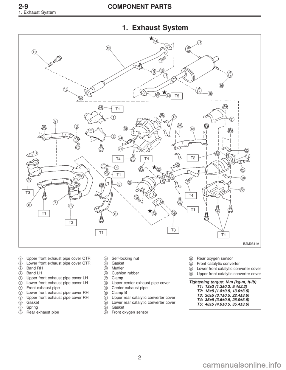
1. Exhaust System
B2M0311A
�1Upper front exhaust pipe cover CTR
�
2Lower front exhaust pipe cover CTR
�
3Band RH
�
4Band LH
�
5Upper front exhaust pipe cover LH
�
6Lower front exhaust pipe cover LH
�
7Front exhaust pipe
�
8Lower front exhaust pipe cover RH
�
9Upper front exhaust pipe cover RH
�
10Gasket
�
11Spring
�
12Rear exhaust pipe�
13Self-locking nut
�
14Gasket
�
15Muffler
�
16Cushion rubber
�
17Clamp
�
18Upper center exhaust pipe cover
�
19Center exhaust pipe
�
20Clamp B
�
21Upper rear catalytic converter cover
�
22Lower rear catalytic converter cover
�
23Gasket
�
24Front oxygen sensor�
25Rear oxygen sensor
�
26Front catalytic converter
�
27Lower front catalytic converter cover
�
28Upper front catalytic converter cover
Tightening torque: N⋅m (kg-m, ft-lb)
T1: 13±3 (1.3±0.3, 9.4±2.2)
T2: 18±5 (1.8±0.5, 13.0±3.6)
T3: 30±5 (3.1±0.5, 22.4±3.6)
T4: 35±5 (3.6±0.5, 26.0±3.6)
T5: 48±5 (4.9±0.5, 35.4±3.6)
2
2-9COMPONENT PARTS
1. Exhaust System
Page 215 of 2248
G2M0544
1. Front Exhaust Pipe and Center
Exhaust Pipe
A: REMOVAL
1) Disconnect front oxygen sensor connector.
B2M0312
2) Lift-up the vehicle.
3) Disconnect rear oxygen sensor connector.
B2M0055
4) Separate center exhaust pipe from rear exhaust pipe.
B2M0054
5) Remove bolts which hold front exhaust pipe onto cylin-
der heads.
B2M0313
6) Remove front exhaust pipe and center exhaust pipe
from hanger bracket.
CAUTION:
Be careful not to pull down front exhaust pipe and
center exhaust pipe.
3
2-9SERVICE PROCEDURE
1. Front Exhaust Pipe and Center Exhaust Pipe
Page 217 of 2248
B2M0313
5) Tighten bolt which holds center exhaust pipe to hanger
bracket.
Tightening torque:
35±5 N⋅m (3.6±0.5 kg-m, 26.0±3.6 ft-lb)
B2M0312
6) Connect rear oxygen sensor connector.
G2M0544
7) Lower the vehicle.
8) Connect front oxygen sensor connector.
B2M0055
2. Rear Exhaust Pipe
A: REMOVAL
1) Separate rear exhaust pipe from center exhaust pipe.
B2M0061
2) Separate rear exhaust pipe from muffler.
CAUTION:
Be careful not to pull down rear exhaust pipe.
5
2-9SERVICE PROCEDURE
1. Front Exhaust Pipe and Center Exhaust Pipe - 2. Rear Exhaust Pipe
 Lift-up the vehicle.
4) Apply SUBARU CRC or its equivalent to threaded por-
tion of front oxygen sensor, and leave it for one minute or
more.
SUBARU CRC (Part No. 004301003)
G2M0411
5) Remove front")
 Lift-up the vehicle.
2) Disconnect connector from rear oxygen sensor.
3) Apply SUBARU CRC or its equivalent to threaded por-
tion of rear oxygen sensor, and")
 Disconnect connector from camshaft position sensor.
G2M0417
2) Remove camshaft position sensor from camshaft sup-
port LH.
3) Instal")
 Disconnect connector from camshaft position sensor.
G2M0417
2) Remove camshaft position sensor from camshaft sup-
port LH.
3) Instal")
 Disconnect front oxygen sensor connector.
B2M0312
2) Lift-up the vehicle.
3) Disconnect rear oxygen sensor connector.
B2M0055
4) Sep")
 Tighten bolt which holds center exhaust pipe to hanger
bracket.
Tightening torque:
35±5 N⋅m (3.6±0.5 kg-m, 26.0±3.6 ft-lb)
B2M0312
6) Connect rear oxygen sensor connector.
G2M0544
7) L")