Page 213 of 2248
1. Fuel System
Trouble and possible cause Corrective action
1. Insufficient fuel supply to the injector
1) Fuel pump will not operate.
�Defective terminal contact.Inspect connections, especially ground, and tighten
securely.
�Trouble in electromagnetic or electronic circuit parts. Replace fuel pump.
2) Lowering of fuel pump function. Replace fuel pump.
3) Clogged dust or water in the fuel filter. Replace fuel filter, clean or replace fuel tank.
4) Clogged or bent fuel pipe or hose. Clean, correct or replace fuel pipe or hose.
5) Air is mixed in the fuel system. Inspect or retighten each connection part.
6) Clogged or bent breather tube or pipe. Clean, correct or replace air breather tube or pipe.
7) Damaged diaphragm of pressure regulator. Replace.
2. Leakage or blow out fuel
1) Loosened joints of the fuel pipe. Retightening.
2) Cracked fuel pipe, hose and fuel tank. Replace.
3) Defective welding part on the fuel tank. Replace.
4) Defective drain packing of the fuel tank. Replace.
5) Clogged or bent air breather tube or air vent tube. Clean, correct or replace air breather tube or air vent tube.
3. Gasoline smell inside of compartment
1)Loose joints at air breather tube, air vent tube and fuel filler
pipe.Retightening.
2) Defective packing air tightness on the fuel saucer. Correct or replace packing.
3) Cracked fuel separator. Replace separator.
4. Defective fuel meter indicator
1) Defective operation of fuel meter unit. Replace.
2) Defective operation of fuel meter. Replace.
5. Noise
1) Large operation noise or vibration of fuel pump. Replace.
NOTE:
When the vehicle is left unattended for an extended period of time, water may accumulate in the fuel
tank.
�To prevent water condensation:
1) Top off the fuel tank or drain the fuel completely.
2) Drain water condensation from the fuel filter.
�Refilling the fuel tank:
Refill the fuel tank while there is still some fuel left in the tank.
�Protecting the fuel system against freezing and water condensation:
1) Cold areas
In snow-covered areas, mountainous areas, skiing areas, etc. where ambient temperatures drop
below 0°C (32°F) throughout the winter season, use an anti-freeze solution in the cooling system.
Refueling will also complement the effect of anti-freeze solution each time the fuel level drops to about
one-half. After the winter season, drain water which may have accumulated in the fuel filter and fuel
tank in the manner same as that described under affected areas as below.
2) Affected areas
When water condensation is notched in the fuel filter, drain water from both the fuel filter and fuel tank
or use a water removing agent (or anti-freeze solution) in the fuel tank.
�Observe the instructions, notes, etc., indicated on the label affixed to the anti-freeze solution (water
removing agent) container before use.
22
2-8DIAGNOSTICS
1. Fuel System
Page 240 of 2248
2. Engine
A: REMOVAL
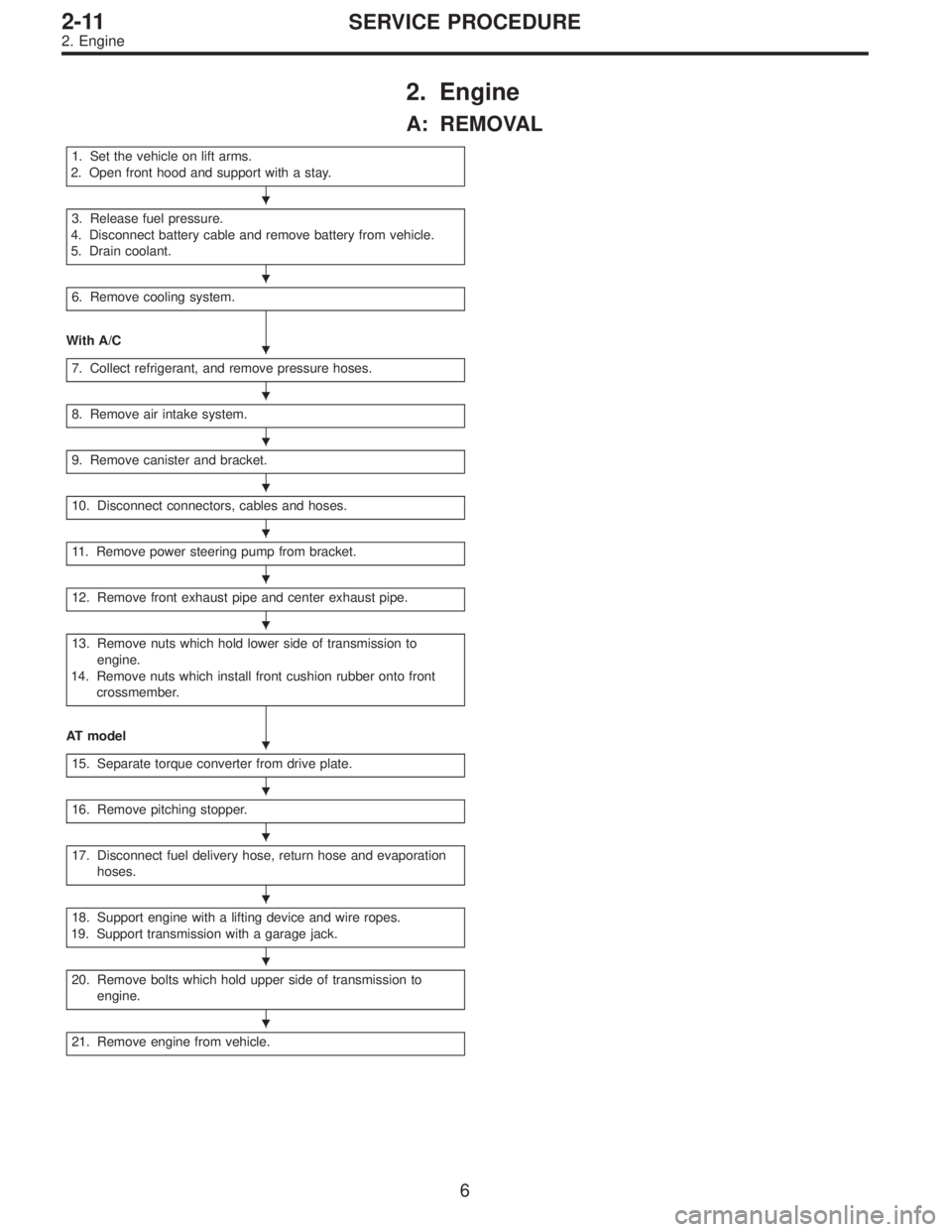
1. Set the vehicle on lift arms.
2. Open front hood and support with a stay.
3. Release fuel pressure.
4. Disconnect battery cable and remove battery from vehicle.
5. Drain coolant.
6. Remove cooling system.
With A/C
7. Collect refrigerant, and remove pressure hoses.
8. Remove air intake system.
9. Remove canister and bracket.
10. Disconnect connectors, cables and hoses.
11. Remove power steering pump from bracket.
12. Remove front exhaust pipe and center exhaust pipe.
13. Remove nuts which hold lower side of transmission to
engine.
14. Remove nuts which install front cushion rubber onto front
crossmember.
AT model
15. Separate torque converter from drive plate.
16. Remove pitching stopper.
17. Disconnect fuel delivery hose, return hose and evaporation
hoses.
18. Support engine with a lifting device and wire ropes.
19. Support transmission with a garage jack.
20. Remove bolts which hold upper side of transmission to
engine.
21. Remove engine from vehicle.
�
�
�
�
�
�
�
�
�
�
�
�
�
�
�
6
2-11SERVICE PROCEDURE
2. Engine
Page 1211 of 2248
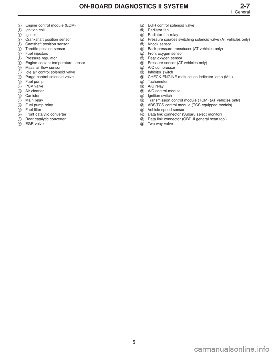
�1Engine control module (ECM)
�
2Ignition coil
�
3Ignitor
�
4Crankshaft position sensor
�
5Camshaft position sensor
�
6Throttle position sensor
�
7Fuel injectors
�
8Pressure regulator
�
9Engine coolant temperature sensor
�
10Mass air flow sensor
�
11Idle air control solenoid valve
�
12Purge control solenoid valve
�
13Fuel pump
�
14PCV valve
�
15Air cleaner
�
16Canister
�
17Main relay
�
18Fuel pump relay
�
19Fuel filter
�
20Front catalytic converter
�
21Rear catalytic converter
�
22EGR valve�
23EGR control solenoid valve
�
24Radiator fan
�
25Radiator fan relay
�
26Pressure sources switching solenoid valve (AT vehicles only)
�
27Knock sensor
�
28Back-pressure transducer (AT vehicles only)
�
29Front oxygen sensor
�
30Rear oxygen sensor
�
31Pressure sensor (AT vehicles only)
�
32A/C compressor
�
33Inhibitor switch
�
34CHECK ENGINE malfunction indicator lamp (MIL)
�
35Tachometer
�
36A/C relay
�
37A/C control module
�
38Ignition switch
�
39Transmission control module (TCM) (AT vehicles only)
�
40ABS/TCS control module (TCS equipped models)
�
41Vehicle speed sensor
�
42Data link connector (Subaru select monitor)
�
43Data link connector (OBD-II general scan tool)
�
44Two way valve
5
2-7ON-BOARD DIAGNOSTICS II SYSTEM
1. General
Page 1221 of 2248
OBD0003B
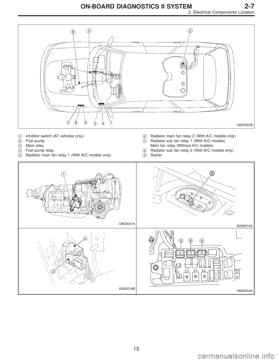
�1Inhibitor switch (AT vehicles only)
�
2Fuel pump
�
3Main relay
�
4Fuel pump relay
�
5Radiator main fan relay 1 (With A/C models only)�
6Radiator main fan relay 2 (With A/C models only)
�
7Radiator sub fan relay 1 (With A/C models)
Main fan relay (Without A/C models)
�
8Radiator sub fan relay 2 (With A/C models only)
�
9Starter
OBD0047AB2M0216A
B2M0218BOBD0034A
15
2-7ON-BOARD DIAGNOSTICS II SYSTEM
2. Electrical Components Location
Page 1225 of 2248
B2M0430B
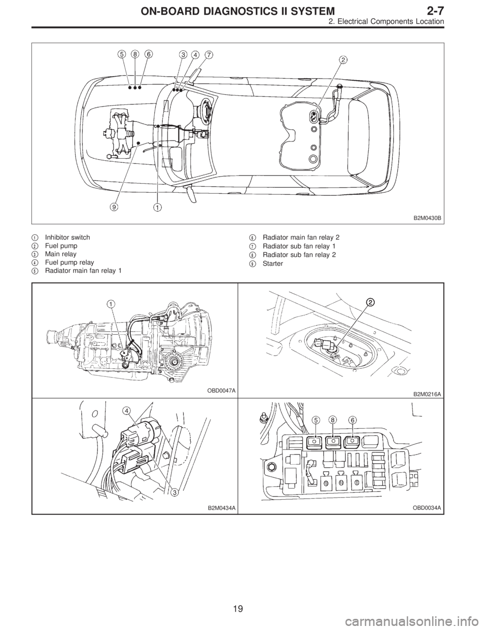
�1Inhibitor switch
�
2Fuel pump
�
3Main relay
�
4Fuel pump relay
�
5Radiator main fan relay 1�
6Radiator main fan relay 2
�
7Radiator sub fan relay 1
�
8Radiator sub fan relay 2
�
9Starter
OBD0047AB2M0216A
B2M0434AOBD0034A
19
2-7ON-BOARD DIAGNOSTICS II SYSTEM
2. Electrical Components Location
Page 1253 of 2248
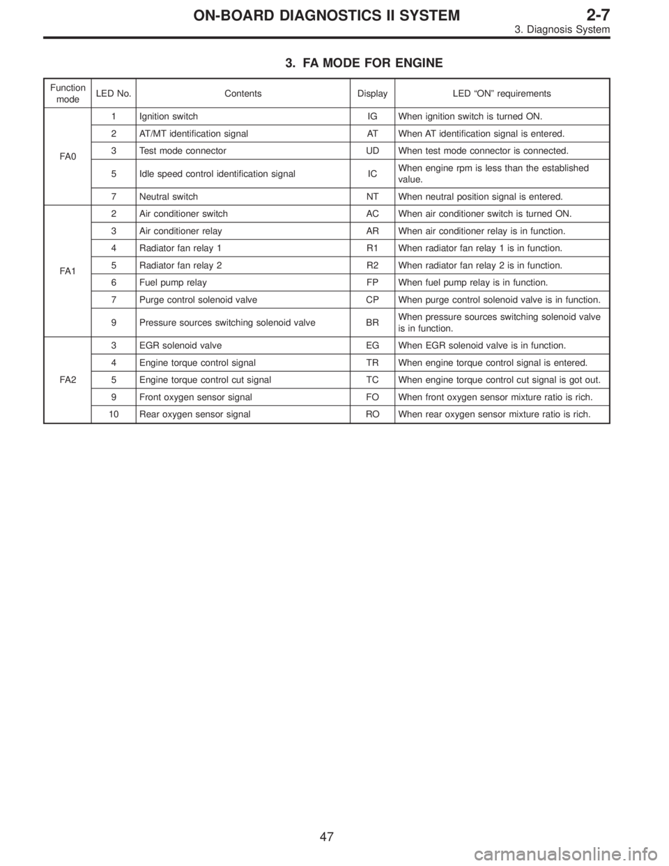
3. FA MODE FOR ENGINE
Function
modeLED No. Contents Display LED“ON”requirements
FA 01 Ignition switch IG When ignition switch is turned ON.
2 AT/MT identification signal AT When AT identification signal is entered.
3 Test mode connector UD When test mode connector is connected.
5 Idle speed control identification signal ICWhen engine rpm is less than the established
value.
7 Neutral switch NT When neutral position signal is entered.
FA 12 Air conditioner switch AC When air conditioner switch is turned ON.
3 Air conditioner relay AR When air conditioner relay is in function.
4 Radiator fan relay 1 R1 When radiator fan relay 1 is in function.
5 Radiator fan relay 2 R2 When radiator fan relay 2 is in function.
6 Fuel pump relay FP When fuel pump relay is in function.
7 Purge control solenoid valve CP When purge control solenoid valve is in function.
9 Pressure sources switching solenoid valve BRWhen pressure sources switching solenoid valve
is in function.
FA 23 EGR solenoid valve EG When EGR solenoid valve is in function.
4 Engine torque control signal TR When engine torque control signal is entered.
5 Engine torque control cut signal TC When engine torque control cut signal is got out.
9 Front oxygen sensor signal FO When front oxygen sensor mixture ratio is rich.
10 Rear oxygen sensor signal RO When rear oxygen sensor mixture ratio is rich.
47
2-7ON-BOARD DIAGNOSTICS II SYSTEM
3. Diagnosis System
Page 1254 of 2248
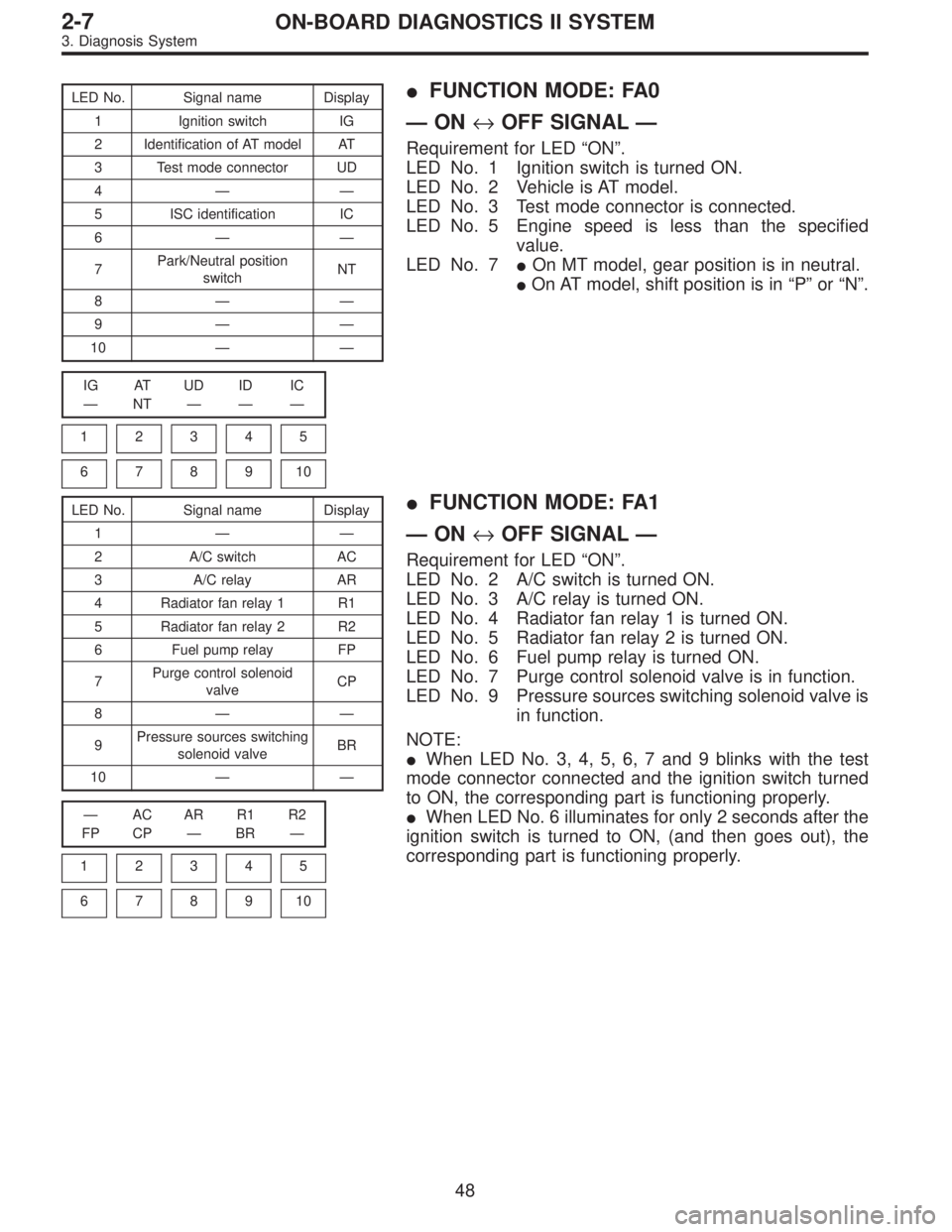
LED No. Signal name Display
1 Ignition switch IG
2 Identification of AT model AT
3 Test mode connector UD
4——
5 ISC identification IC
6——
7Park/Neutral position
switchNT
8——
9——
10——
IG AT UD ID IC
—NT———
1
2345
678910
�FUNCTION MODE: FA0
—ON↔OFF SIGNAL—
Requirement for LED“ON”.
LED No. 1 Ignition switch is turned ON.
LED No. 2 Vehicle is AT model.
LED No. 3 Test mode connector is connected.
LED No. 5 Engine speed is less than the specified
value.
LED No. 7�On MT model, gear position is in neutral.
�On AT model, shift position is in“P”or“N”.
LED No. Signal name Display
1——
2 A/C switch AC
3 A/C relay AR
4 Radiator fan relay 1 R1
5 Radiator fan relay 2 R2
6 Fuel pump relay FP
7Purge control solenoid
valveCP
8——
9Pressure sources switching
solenoid valveBR
10——
—AC AR R1 R2
FP CP—BR—
1
2345
678910
�FUNCTION MODE: FA1
—ON↔OFF SIGNAL—
Requirement for LED“ON”.
LED No. 2 A/C switch is turned ON.
LED No. 3 A/C relay is turned ON.
LED No. 4 Radiator fan relay 1 is turned ON.
LED No. 5 Radiator fan relay 2 is turned ON.
LED No. 6 Fuel pump relay is turned ON.
LED No. 7 Purge control solenoid valve is in function.
LED No. 9 Pressure sources switching solenoid valve is
in function.
NOTE:
�When LED No. 3, 4, 5, 6, 7 and 9 blinks with the test
mode connector connected and the ignition switch turned
to ON, the corresponding part is functioning properly.
�When LED No. 6 illuminates for only 2 seconds after the
ignition switch is turned to ON, (and then goes out), the
corresponding part is functioning properly.
48
2-7ON-BOARD DIAGNOSTICS II SYSTEM
3. Diagnosis System
Page 1271 of 2248
4. Cautions
A: SUPPLEMENTAL RESTRAINT SYSTEM
“AIRBAG”
Airbag system wiring harness is routed near the engine
control module (ECM), main relay and fuel pump relay.
CAUTION:
�All Airbag system wiring harness and connectors
are colored yellow. Do not use electrical test equip-
ment on these circuit.
�Be careful not to damage Airbag system wiring har-
ness when servicing the engine control module (ECM),
transmission control module (TCM), main relay and
fuel pump relay.
B: PRECAUTIONS
1) Never connect the battery in reverse polarity.
�The ECM will be destroyed instantly.
�The fuel injector and other part will be damaged in just
a few minutes more.
2) Do not disconnect the battery terminals while the
engine is running.
�A large counter electromotive force will be generated in
the alternator, and this voltage may damage electronic
parts such as ECM, etc.
3) Before disconnecting the connectors of each sensor
and the ECM, be sure to turn OFF the ignition switch.
4) Before removing ECM from the located position, dis-
connect two cables on battery.
�Otherwise, the ECM may be damaged.
5) The connectors to each sensor in the engine compart-
ment and the harness connectors on the engine side and
body side are all designed to be waterproof. However, it is
still necessary to take care not to allow water to get into the
connectors when washing the vehicle, or when servicing
the vehicle on a rainy day.
6) Every MFI-related part is a precision part. Do not drop
them.
7) Observe the following cautions when installing a radio
in MFI equipped models.
CAUTION:
�The antenna must be kept as far apart as possible
from the control unit.
(The ECM is located under the steering column, inside
of the instrument panel lower trim panel.)
�The antenna feeder must be placed as far apart as
possible from the ECM and MFI harness.
�Carefully adjust the antenna for correct matching.
65
2-7ON-BOARD DIAGNOSTICS II SYSTEM
4. Cautions