Page 62 of 976
09LUBRICANTS, FLUIDS AND CAPACITIES
6
INFORMATION RECOMMENDED FUEL
Petrol engines
- with catalytic converter unleaded only, 95 RON (USA 90 CLC or AKI)................................................
- non catalytic, 9.35:1 compression ratio leaded 97 RON/unleaded 95 RON.......................
- non catalytic, 8.13:1 compression ratio leaded 90 RON/unleaded 95 RON.......................
- Australia minimum 91 RON unleaded......................................................................
Diesel engines
300Tdi Diesel fuel oil,distillate,diesel fuel, automotive gas or...........................................................................
Derv to British standard 2869, Class A1 or A2
Using fuel with an octane rating lower than stated above could seriously impair vehicle performance.
CAUTION: Do not use oxygenated fuels such as blends of methanol/ gasoline or ethanol/gasoline
(e.g. 'Gasohol'). Take care not to spill fuel during refuelling.
Page 65 of 976

MAINTENANCE
3
MAINTENANCE VEHICLE EXTERIOR
CHECK/ADJUST HEADLAMP ALIGNMENT
Check/adjust headlamp and auxiliary alignment.
CHECK FRONT WHEEL ALIGNMENT
Use recognised wheel alignment equipment to
perform this check and adjustment.
See STEERING,
Adjustment, Front Wheel Alignment
REMOVE WHEELS, CHECK TYRES
Check tyres (including spare) for compliance with
manufacturers' specification.
Check visually for cuts, lumps, bulges, uneven tread
wear and tread depth. Check road wheels for
damage.
Check/adjust tyre pressures.
CHECK/TIGHTEN TOWING BRACKET FITTINGSINSPECT BRAKE PADS FOR WEAR, CALIPERS
FOR LEAKS AND CONDITION
Check thickness of brake pads, fit new pads if
minimum thickness is less than 3,0mm. Check brake
pads for oil contamination. If new brake pads required.
See BRAKES, Repair, Front Brake Pads
or.See BRAKES, Repair, Rear Brake Pads
WARNING: When renewing brake pads, it
is essential that only genuine components
with correct grade of lining are used.
Always fit new pads as complete axle sets, NEVER
individually or as a single wheel set. Serious
consequences could result from out of balance
braking due to mixing of linings.
Refit road wheels
Fit road wheels in original hub position. Secure in
position with wheel nuts, do not fully tighten wheel
nuts at this stage, lower vehicle and finally tighten
wheel nuts to correct torque.
Alloy wheels:
130 Nm.
Steel wheels:130 Nm.
LUBRICATE ALL HINGES, DOOR CHECK
MECHANISMS, BONNET [HOOD] CATCHES AND
FUEL FILLER FLAP
Page 66 of 976
![LAND ROVER DISCOVERY 1995 Service Repair Manual 10MAINTENANCE
4
MAINTENANCE UNDER BONNET [HOOD] MAINTENANCE
CHECK COOLING/HEATER SYSTEMS
Check cooling/heater systems for leaks and hoses for
security and condition.
Cooling system hoses should be cha LAND ROVER DISCOVERY 1995 Service Repair Manual 10MAINTENANCE
4
MAINTENANCE UNDER BONNET [HOOD] MAINTENANCE
CHECK COOLING/HEATER SYSTEMS
Check cooling/heater systems for leaks and hoses for
security and condition.
Cooling system hoses should be cha](/manual-img/64/57245/w960_57245-65.png)
10MAINTENANCE
4
MAINTENANCE UNDER BONNET [HOOD] MAINTENANCE
CHECK COOLING/HEATER SYSTEMS
Check cooling/heater systems for leaks and hoses for
security and condition.
Cooling system hoses should be changed at first
signs of deterioration.
CHECK CONDITION OF ENGINE MOUNTING
RUBBERS
CHECK BRAKE SERVO HOSE FOR SECURITY
AND CONDITION
CHECK FUEL EVAPORATIVE LOSS CONTROL
SYSTEM FOR LEAKS - V8i CATALYST, Mpi
CHECK FUEL FILLER CAP SEAL FOR LEAKS - V8i
- CATALYST, Mpi
CHECK CONDITION OF HEATER PLUG WIRING
FOR FRAYING, CHAFING AND DETERIORATION -
Tdi
CHECK IGNITION WIRING
Check ignition wiring and high tension leads for
fraying, chafing and deterioration.
CLEAN DISTRIBUTOR CAP - V8i
The electronic ignition employs a Lucas 35DLM8
distributor.
Internal operating parts of distributor are pre-set at
factory and do not normally require resetting.
Adjustments should only be made if unit is known to
be faulty or damaged. Distributor maintenance
consists of following items.
1.Clean outer surfaces of distributor cap to remove
dirt, grease etc.
2.Unclip cap, check cap for cracks.
3.Wipe inside cap with lint free cloth.
4.Check rotor arm, cap and flash shield tracking.
DO NOT DISTURB clear plastic insulating
cover (flash shield) which protects magnetic
pick-up module.
LUBRICATE DISTRIBUTOR ROTOR SPINDLE - V8i
Apply a spot of clean engine oil into rotor spindle after
rotor arm has been removed.
CLEAN/ADJUST SPARK PLUGS - V8i CATALYST
RENEW SPARK PLUGS V8i - V8i CATALYST
Clean, adjust and renew
1.Take great care when fitting spark plugs not to
cross-thread plug, otherwise costly damage to
cylinder head will result.
Page 69 of 976

MAINTENANCE
7
MAINTENANCE
CHECK/ADJUST VALVE CLEARANCES. - Tdi
Valve adjustment.See GENERAL SPECIFICATION
DATA, Information, 300 Tdi Engine
RENEW FUEL FILTER ELEMENT - Tdi
Drain off water and sediment
CAUTION: It is essential that any water
and sediment in fuel filter is drained off, as
water in fuel can result in damage to
injection pump.
1.Hold a small receptacle beneath drain cock.
Unscrew the drain cock half a turn.
2.Drain off water and sediment.
3.Tighten the drain cock immediately fuel starts to
flow from drain cock.
NOTE: Any delay in tightening drain cock
when fuel starts to flow could possibly
mean bleeding fuel system.
Renew fuel filter element
1.Clean area around filter, place a container
beneath.
2.Unscrew filter, a quantity of fuel will be released,
and discard filter.
3.Wet seal of new filter with fuel.
4.Screw new filter into position.
5.Ensure that drain cock is secure.
RENEW AIR CLEANER ELEMENT V8i CATALYST
Mpi - Tdi - V8i NON CATALYST
To renew air cleaner element - V8i, Mpi,Tdi
See FUEL SYSTEM, Repair, Air Cleaner
Page 78 of 976

10MAINTENANCE
16
MAINTENANCE
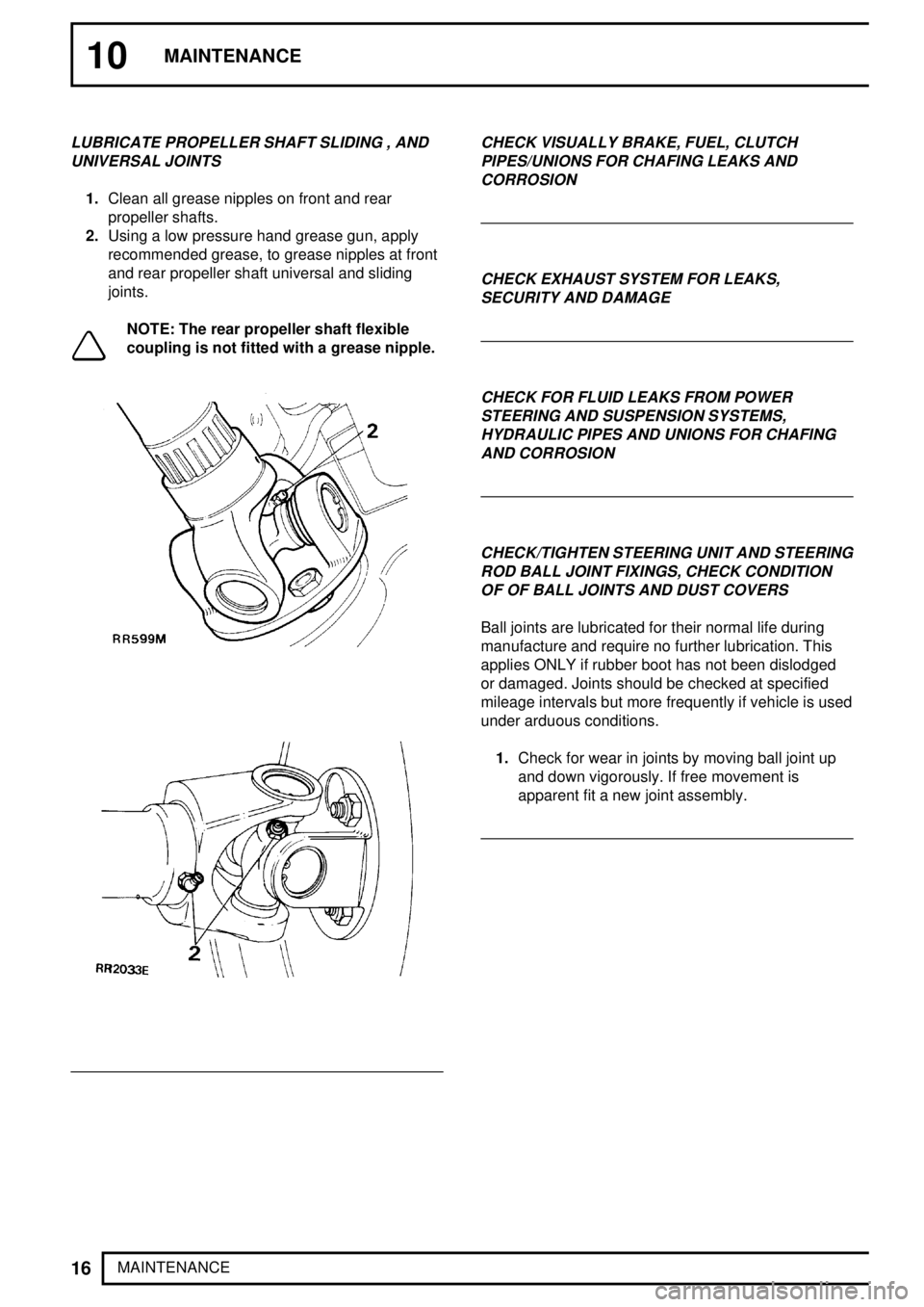
LUBRICATE PROPELLER SHAFT SLIDING , AND
UNIVERSAL JOINTS
1.Clean all grease nipples on front and rear
propeller shafts.
2.Using a low pressure hand grease gun, apply
recommended grease, to grease nipples at front
and rear propeller shaft universal and sliding
joints.
NOTE: The rear propeller shaft flexible
coupling is not fitted with a grease nipple.
CHECK VISUALLY BRAKE, FUEL, CLUTCH
PIPES/UNIONS FOR CHAFING LEAKS AND
CORROSION
CHECK EXHAUST SYSTEM FOR LEAKS,
SECURITY AND DAMAGE
CHECK FOR FLUID LEAKS FROM POWER
STEERING AND SUSPENSION SYSTEMS,
HYDRAULIC PIPES AND UNIONS FOR CHAFING
AND CORROSION
CHECK/TIGHTEN STEERING UNIT AND STEERING
ROD BALL JOINT FIXINGS, CHECK CONDITION
OF OF BALL JOINTS AND DUST COVERS
Ball joints are lubricated for their normal life during
manufacture and require no further lubrication. This
applies ONLY if rubber boot has not been dislodged
or damaged. Joints should be checked at specified
mileage intervals but more frequently if vehicle is used
under arduous conditions.
1.Check for wear in joints by moving ball joint up
and down vigorously. If free movement is
apparent fit a new joint assembly.
Page 79 of 976

MAINTENANCE
17
MAINTENANCE
CHECK/TIGHTEN FRONT AND REAR AXLE
SUSPENSION LINK FIXINGS, CHECK CONDITION
OF MOUNTING RUBBERS
DRAIN FUEL SEDIMENTER - Tdi
Fuel sedimenter
The sedimenter is attached to left-hand side of
chassis frame near fuel tank. It increases the working
life of the fuel filter by removing larger droplets of
water and larger particles of foreign matter from fuel.
Drain off water
1.Loosen drain plug, allow water to run out.
Tighten plug immediately pure diesel fuel starts
to flow.
RENEW FUEL FILTER
WARNING: Ensure that fuel handling
precautions given in Section 01 -
Introduction regarding fuel handling are
strictly adhered to when carrying out following
instructions.
See INTRODUCTION, Information,
Fuel Handling Precautions
WARNING: The spilling of fuel is
unavoidable during this operation. Ensure
that all necessary precautions are taken to
prevent fire and explosion.
1.Depressurise fuel system.
See FUEL SYSTEM,
Repair, Depressurising Fuel System
2.The fuel line filter is located on right hand
chassis side member forward of fuel tank filler
neck. Access to filter is gained through right
hand rear wheel arch.
3.Thoroughly clean area around hose connections
to prevent ingress of foreign matter into fuel
system.
4.Loosen two fuel unions and remove hoses from
filter canister.
5.Release securing bolt and bracket, remove filter
from chassis side member.
6.Fit a new filter observing direction of flow arrow
on canister.
7.Fit inlet and outlet hoses. Tighten to
30 Nm.
8.Refit fuel pump relay.
9.Reconnect battery negative lead.
10.Recode radio.
11.Start engine and inspect hose connections for
fuel leaks.
Page 85 of 976

12ENGINE
4
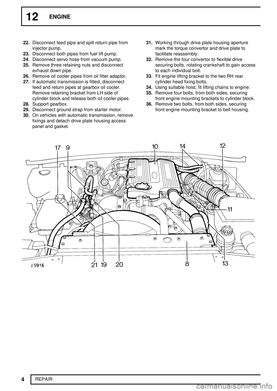
REPAIR 22.Disconnect feed pipe and spill return pipe from
injector pump.
23.Disconnect both pipes from fuel lift pump.
24.Disconnect servo hose from vacuum pump.
25.Remove three retaining nuts and disconnect
exhaust down pipe.
26.Remove oil cooler pipes from oil filter adaptor.
27.If automatic transmission is fitted, disconnect
feed and return pipes at gearbox oil cooler.
Remove retaining bracket from LH side of
cylinder block and release both oil cooler pipes.
28.Support gearbox.
29.Disconnect ground strap from starter motor.
30.On vehicles with automatic transmission, remove
fixings and detach drive plate housing access
panel and gasket.31.Working through drive plate housing aperture
mark the torque convertor and drive plate to
facilitate reassembly.
32.Remove the four convertor to flexible drive
securing bolts, rotating crankshaft to gain access
to each individual bolt.
33.Fit engine lifting bracket to the two RH rear
cylinder head fixing bolts.
34.Using suitable hoist, fit lifting chains to engine.
35.Remove four bolts, from both sides, securing
front engine mounting brackets to cylinder block.
36.Remove two bolts, from both sides, securing
front engine mounting bracket to bell housing.
Page 91 of 976
12ENGINE
10
REPAIR
21.With lip side leading, drive-in seal squarely using
special tool LRT-12-082.
22.Refit gear.
FUEL INJECTION PUMP GEAR
Service repair no - 19.30.06
Remove
23.Slacken the three bolts on front of gear.
CAUTION: It is important to ensure that
when the injection pump is locked no
attempt must be made to rotate it. Take
care not to allow the crankshaft to be turned.24.Remove special tool pin from gear.
25.Remove three bolts and withdraw plate and
gear.
Refit
26.Fit gear and plate and secure with three bolts.
27.Insert pin from special tool LRT-12-045 in
injection pump gear and through into pump
flange.