1995 LAND ROVER DISCOVERY fuel
[x] Cancel search: fuelPage 93 of 976
12ENGINE
12
REPAIR FRONT COVER/TIMING GEAR HOUSING GASKET
Service repair no - 12.65.10
Remove
1.Remove timing belt and gears.
See Camshaft
Drive Belt and Gears
2.Remove fuel injection pump.See FUEL
SYSTEM, Repair, Fuel Injection Pump and
Timing
3.Remove engine oil sump.See Oil Sump
4.Remove oil pick up strainer.See Oil Pick-Up
Strainer
5.Remove bolts securing timing gear housing to
block.
6.Withdraw timing gear housing complete with
gasket.
7.Clean all gasket material from mating faces.
Refit
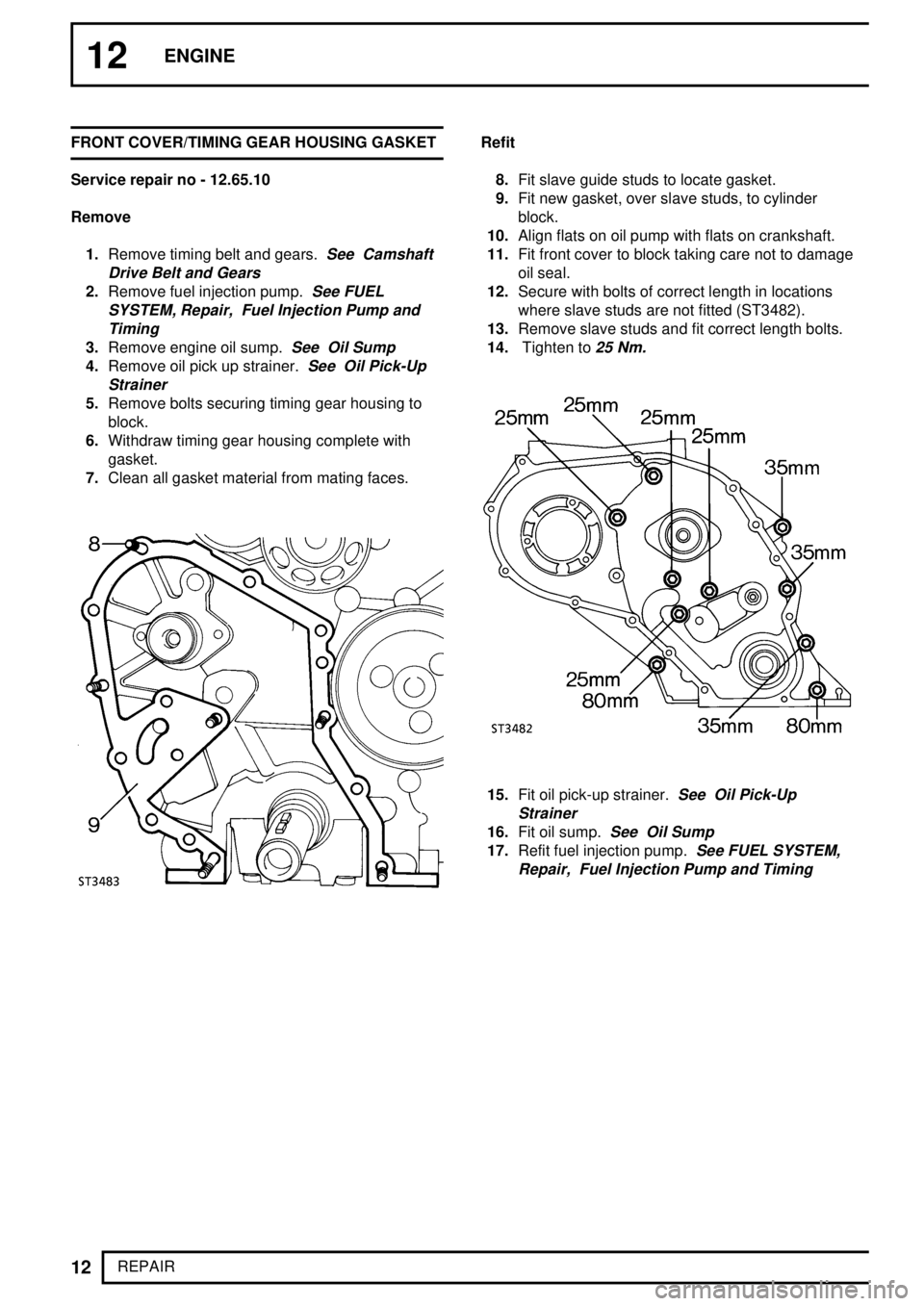
8.Fit slave guide studs to locate gasket.
9.Fit new gasket, over slave studs, to cylinder
block.
10.Align flats on oil pump with flats on crankshaft.
11.Fit front cover to block taking care not to damage
oil seal.
12.Secure with bolts of correct length in locations
where slave studs are not fitted (ST3482).
13.Remove slave studs and fit correct length bolts.
14.Tighten to
25 Nm.
15.Fit oil pick-up strainer.See Oil Pick-Up
Strainer
16.Fit oil sump.See Oil Sump
17.Refit fuel injection pump.See FUEL SYSTEM,
Repair, Fuel Injection Pump and Timing
Page 101 of 976
![LAND ROVER DISCOVERY 1995 Service Repair Manual 12ENGINE
20
REPAIR CYLINDER HEAD GASKET
Service repair no - 12.29.02
Remove
1.Disconnect battery negative lead.
2.Remove bonnet [Hood].
See CHASSIS AND
BODY, Repair, Bonnet [Hood]
3.Drain coolant.
4.R LAND ROVER DISCOVERY 1995 Service Repair Manual 12ENGINE
20
REPAIR CYLINDER HEAD GASKET
Service repair no - 12.29.02
Remove
1.Disconnect battery negative lead.
2.Remove bonnet [Hood].
See CHASSIS AND
BODY, Repair, Bonnet [Hood]
3.Drain coolant.
4.R](/manual-img/64/57245/w960_57245-100.png)
12ENGINE
20
REPAIR CYLINDER HEAD GASKET
Service repair no - 12.29.02
Remove
1.Disconnect battery negative lead.
2.Remove bonnet [Hood].
See CHASSIS AND
BODY, Repair, Bonnet [Hood]
3.Drain coolant.
4.Remove air cleaner assembly.
See FUEL
SYSTEM, Repair, Air Cleaner
5.Detach crankcase ventilation valve and side
breather hose from rocker cover and move to
one side.
6.Remove injection pipes.
7.Disconnect spill rail from fuel injectors.
8.Remove fuel injectors and sealing washers.
Identify each injector to the location from which it
is removed.
See FUEL SYSTEM, Repair,
Injectors
9.Remove inter-connecting harness from glow
plugs.
10.Remove glow plugs.
See FUEL SYSTEM,
Repair, Glow Plugs
11.Remove top hose, radiator to thermostat.
12.Disconnect by-pass hose from thermostat.
13.Disconnect hose, thermostat to water pump.
14.Disconnect water temperature sensor lead.
15.Remove hose inter-cooler to induction manifold.
16.Remove induction manifold.
See MANIFOLD
AND EXHAUST SYSTEM, Repair, Exhaust
Manifold - Tdi
17.Remove exhaust manifold and turbocharger
assembly.
See MANIFOLD AND EXHAUST
SYSTEM, Repair, Exhaust Manifold - Tdi
18.Disconnect heater hose from water pump and
move heater rail aside.
19.Disconnect heater hose from rear of cylinder
head.
20.Remove bolt securing air cleaner mounting
bracket to support strut.
21.Remove bolt securing harness bracket to
cylinder head.
22.Remove rear lifting bracket, this will also release
clips securing transmission and engine breather
pipes and multiplug. Note loose spacer under
clip securing engine breather pipe and multiplug.
Page 105 of 976
Tdi
1
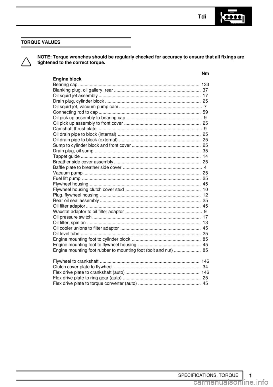
SPECIFICATIONS, TORQUE TORQUE VALUES
NOTE: Torque wrenches should be regularly checked for accuracy to ensure that all fixings are
tightened to the correct torque.
Nm
Engine block
Bearing cap 133...............................................................................................
Blanking plug, oil gallery, rear 37....................................................................
Oil squirt jet assembly 17................................................................................
Drain plug, cylinder block 25...........................................................................
Oil squirt jet, vacuum pump cam 7.................................................................
Connecting rod to cap 59................................................................................
Oil pick up assembly to bearing cap 9...........................................................
Oil pick up assembly to front cover 25............................................................
Camshaft thrust plate 9..................................................................................
Oil drain pipe to block (internal) 25.................................................................
Oil drain pipe to block (external) 25................................................................
Sump to cylinder block and front cover 25......................................................
Drain plug, oil sump 35...................................................................................
Tappet guide 14..............................................................................................
Breather side cover assembly 25....................................................................
Baffle plate to breather side cover 4..............................................................
Vacuum pump 25............................................................................................
Fuel lift pump 25.............................................................................................
Flywheel housing 45.......................................................................................
Flywheel housing clutch cover stud 10...........................................................
Plug, flywheel housing 12...............................................................................
Rear oil seal assembly 25...............................................................................
Oil filter adaptor 45..........................................................................................
Waxstat adaptor to oil filter adaptor 9............................................................
Oil pressure switch 17.....................................................................................
Oil filter, spin on 13.........................................................................................
Oil cooler unions to filter adaptor 45...............................................................
Oil level tube 25..............................................................................................
Engine mounting foot to cylinder block 85......................................................
Engine mounting foot to flywheel housing 45.................................................
Engine mounting foot rubber to mounting foot (bolt and nut) 85.....................
Flywheel to crankshaft 146..............................................................................
Clutch cover plate to flywheel 34....................................................................
Flex drive plate to crankshaft (auto) 146..........................................................
Flex drive plate to ring gear (auto) 25.............................................................
Flex drive plate to torque converter (auto) 45.................................................
Page 106 of 976
12ENGINE
2
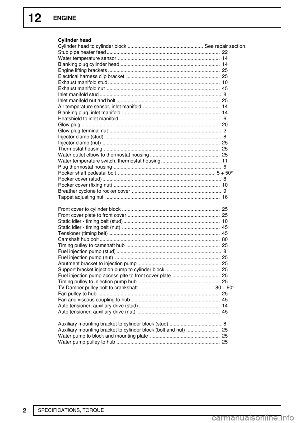
SPECIFICATIONS, TORQUECylinder head
Cylinder head to cylinder block See repair section......................................................
Stub pipe heater feed 22.................................................................................
Water temperature sensor 14.........................................................................
Blanking plug cylinder head 14.......................................................................
Engine lifting brackets 25................................................................................
Electrical harness clip bracket 25...................................................................
Exhaust manifold stud 10................................................................................
Exhaust manifold nut 45.................................................................................
Inlet manifold stud 8.......................................................................................
Inlet manifold nut and bolt 25..........................................................................
Air temperature sensor, inlet manifold 14.......................................................
Blanking plug, inlet manifold 14......................................................................
Heatshield to inlet manifold 6.........................................................................
Glow plug 20...................................................................................................
Glow plug terminal nut 2................................................................................
Injector clamp (stud) 8...................................................................................
Injector clamp (nut) 25....................................................................................
Thermostat housing 25...................................................................................
Water outlet elbow to thermostat housing 25..................................................
Water temperature switch, thermostat housing 11..........................................
Plug thermostat housing 6.............................................................................
Rocker shaft pedestal bolt 5 + 50° .....................................................................
Rocker cover (stud) 8.....................................................................................
Rocker cover (fixing nut) 10............................................................................
Breather cyclone to rocker cover 9................................................................
Tappet adjusting nut 16..................................................................................
Front cover to cylinder block 25......................................................................
Front cover plate to front cover 25..................................................................
Static idler - timing belt (stud) 10.....................................................................
Static idler - timing belt (nut) 45......................................................................
Tensioner (timing belt) 45...............................................................................
Camshaft hub bolt 80......................................................................................
Timing pulley to camshaft hub 25...................................................................
Fuel injection pump (stud) 8...........................................................................
Fuel injection pump (nut) 25...........................................................................
Abutment bracket to injection pump 25...........................................................
Support bracket injection pump to cylinder block 25.......................................
Fuel injection pump access plte to front cover plate 25..................................
Timing pulley to injection pump hub 25...........................................................
TV Damper pulley bolt to crankshaft 80 + 90° .....................................................
Fan pulley to hub 25.......................................................................................
Fan and viscous coupling to hub 45...............................................................
Auto tensioner, auxiliary drive (stud) 14..........................................................
Auto tensioner, auxiliary drive (nut) 45...........................................................
Auxiliary mounting bracket to cylinder block (stud) 8.....................................
Auxiliary mounting bracket to cylinder block (bolt and nut) 25........................
Water pump to block and mounting plate 25..................................................
Water pump pulley to hub 25..........................................................................
Page 107 of 976
Tdi
3
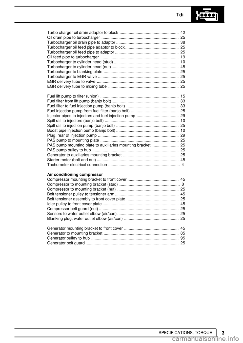
SPECIFICATIONS, TORQUE Turbo charger oil drain adaptor to block 42....................................................
Oil drain pipe to turbocharger 25....................................................................
Turbocharger oil drain pipe to adaptor 38.......................................................
Turbocharger oil feed pipe adaptor to block 25...............................................
Turbocharger oil feed pipe to adaptor 25........................................................
Oil feed pipe to turbocharger 19.....................................................................
Turbocharger to cylinder head (stud) 10.........................................................
Turbocharger to cylinder head (nut) 45...........................................................
Turbocharger to blanking plate 25..................................................................
Turbocharger to EGR valve 25.......................................................................
EGR delivery tube to valve 25........................................................................
EGR delivery tube to mixing tube 25..............................................................
Fuel lift pump to filter (union) 15.....................................................................
Fuel filter from lift pump (banjo bolt) 33...........................................................
Fuel filter to fuel injection pump (banjo bolt) 33..............................................
Fuel injection pump from fuel filter (banjo bolt) 25..........................................
Injector pipes to injectors and fuel injection pump 29.....................................
Spill rail to injectors (banjo bolt) 10.................................................................
Spill rail to injection pump (banjo bolt) 25.......................................................
Boost pipe injection pump (banjo bolt) 10.......................................................
Plug, rear of injection pump 29.......................................................................
PAS pump to mounting plate 25.....................................................................
PAS pump mounting plate to auxiliaries mounting bracket 25........................
PAS pump pulley to hub 25............................................................................
Generator to auxiliaries mounting bracket 25.................................................
Starter motor (bolt and nut) 45........................................................................
Tachometer electrical connection 4...............................................................
Air conditioning compressor
Compressor mounting bracket to front cover 45.............................................
Compressor to mounting bracket (stud) 8......................................................
Compressor to mounting bracket (nut) 25......................................................
Belt tensioner pulley to tensioner arm 45........................................................
Belt tensioner assembly to front cover plate 25..............................................
Idler pulley to front cover plate 45...................................................................
Compressor belt guard (nut) 25......................................................................
Sensors to water outlet elbow (air/con) 25......................................................
Blanking plug, water outlet elbow (air/con) 25................................................
Generator mounting bracket to front cover 45................................................
Generator to mounting bracket 85..................................................................
Generator pulley to hub 95.............................................................................
Generator belt guard 25..................................................................................
Page 109 of 976
V8i
1
DESCRIPTION AND OPERATION DESCRIPTION
The V8i engine has cast aluminium cylinder heads
and cylinder block. The two banks of steel cylinder
liners which are pressed down to stops in the block,
are set at 90°to one another. The three ringed
aluminium pistons transmit the power through the
connecting rods to a cast iron five bearing crankshaft,
which drives the centrally located camshaft via a
duplex type chain.
The electronic ignition distributor is driven by a gear
off the front of the camshaft and the lubrication oil
pump is driven by a gear off the front of the
crankshaft. The overhead inlet and exhaust valves are
operated by rocker shafts, pushrods and self adjusting
hydraulic tappets.
Multiport fuel injection ensures that engine
performance, economy and exhaust emissions are
automatically correct for the demands of highway and
off road operation.
Page 116 of 976
V8i
3
FAULT DIAGNOSIS ENGINE STARTING PROBLEMS
Engine fails to crank in park or neutral (Automatic
Transmission)
1.Is battery in good state of charge?
NO -
See INTRODUCTION, Information,
Jump Starting
YES - Continue.
2.Is automatic transmission inhibitor switch faulty
or gear selection linkage incorrectly adjusted?
YES -
See AUTOMATIC GEARBOX, Repair,
Inhibitor Switch
,
NO -
See Electrical Trouble Shooting
Manual.
If problem is not diagnosed repeat tests, starting
at 1.
Engine fails to crank (Manual Transmission)
1.Is battery in good state of charge?
NO -
See INTRODUCTION, Information,
Jump Starting
YES -See Electrical Trouble Shooting
Manual.
If problem is not diagnosed repeat tests, starting
at 1.
Engine cranks but fails to start
1.Is the cranking speed fast enough (120 rpm)?
NO -
See INTRODUCTION, Information,
Jump Starting
If necessary also.See Electrical Trouble
Shooting Manual.
YES - Continue.
2.Is there combustion in any cylinder?
NO -
See ELECTRICAL, Fault diagnosis,
Lucas Constant Energy Ignition
System - V8i See Electrical Trouble
Shooting Manual.
YES - Continue.
3.Are the fuel supply, tank, pump, ventilation and
emission control systems in correct working
order or the fuel contaminated?
NO -
See FUEL SYSTEM, Repair, Fuel
Filter See FUEL SYSTEM, Repair,
Fuel Tank See FUEL SYSTEM, Repair,
Fuel pump and Sender Unit See
EMISSION CONTROL, Description and
operation, Emission control
If problem is not diagnosed repeat tests, starting
at 2.ENGINE RUNNING PROBLEMS
Engine runs at high speed but will not idle (stops)
Engine idle speed erratic Engine starts but stops
immediately
Engine stalls Engine misfires/hesitation
1.Multiport fuel injection.
See Electrical Trouble
Shooting Manual. See ELECTRICAL, Fault
diagnosis, Lucas Constant Energy Ignition
System - V8i
Check brake vacuum connections.See
BRAKES, Description and operation, Brake
Servo Unit
Check heater/ventilation unit vacuum
connections.
See HEATING AND
VENTILATION, Description and operation,
Heating and Ventilation Unit
If problem is not diagnosed continue.
2.Are HT leads correctly routed and clipped?
NO -
See ELECTRICAL, Repair, Distributor
- V8i
YES - Continue.
3.Is fuel supply, tank, pump, ventilation and
emission control systems in correct working
order or the fuel contaminated?
NO -
See FUEL SYSTEM, Repair, Fuel
Filter See FUEL SYSTEM, Repair,
Fuel Tank See FUEL SYSTEM, Repair,
Fuel Pump and Sender Unit See
EMISSION CONTROL, Description and
operation, Emission Control
If problem is not diagnosed repeat tests, starting
at 1.
Engine lacks power/poor performance
1.Is throttle travel restricted or cable incorrectly
adjusted?
YES - Check thickness of carpets.
See FUEL
SYSTEM, Repair, Throttle Cable See
FUEL SYSTEM, Repair, Accelerator
Pedal
NO - Continue.
2.Are the Ignition and Multiport Fuel Injection
systems in order?
NO -
See Electrical Trouble Shooting
Manual.A1 See ELECTRICAL, Fault
diagnosis, Lucas Constant Energy
Ignition System - V8i See
ELECTRICAL, Repair, Distributor - V8i
YES - Continue.
Page 117 of 976
12ENGINE
4
FAULT DIAGNOSIS 3.Are fuel supply, tank, pump, ventilation and
emission control systems in correct working
order or the fuel contaminated?
NO -
See FUEL SYSTEM, Repair, Fuel
Filter See FUEL SYSTEM, Repair,
Fuel Tank See FUEL SYSTEM, Repair,
Fuel Pump and Sender Unit
YES - Suspect valves held open by hydraulic
tappets due to high oil pressure.
See
Engine Oil Pressure Test
4.Is oil pressure high?
YES - Remove oil filter and cooler adaptor and
check pressure relief valve strainer gauze
for blockage and that the relief valve is
not stuck closed.
See Description and
operation, Description
NO - Carry out cylinder compression tests to
determine condition of head gaskets and
valves.
See Cylinder Compression -
Test
5.Are cylinder compressions satisfactory?
NO -
See Repair, Cylinder Heads - Renew
YES - Check brake vacuum connections.See
BRAKES, Description and operation,
Brake Servo Unit
Check heater/ventilation unit vacuum connections.
See HEATING AND VENTILATION, Description and
operation, Heating and Ventilation Unit
If problem is not diagnosed: Continue.
6.Are the brakes binding?
YES - Investigate cause of binding.
NO - Continue.
7.Automatic Transmission only. Is the Torque
Converter and Transmission operating correctly?
Carry out Road test, Static tests and Stall tests
to determine condition of Automatic
transmission.
If problem is not diagnosed: repeat tests starting at 1.Engine backfires into exhaust system
1.Are there any leaking joints/connections or holes
in the exhaust system?
YES -
See MANIFOLD AND EXHAUST
SYSTEM, Repair, Exhaust System
Complete
NO - Continue.
2.Is distributor fitted correctly, HT leads in correct
firing order and routed correctly?
NO -
See ELECTRICAL, Repair, Distributor
- V8i
YES - Continue.
3.Is air fuel ratio correct?
NO - Check multiport fuel injection.
See
Electrical Trouble Shooting Manual.
Check brake vacuum connections.See
BRAKES, Description and operation, Brake
Servo Unit
Check heater/ventilation unit vacuum
connections.
See HEATING AND
VENTILATION, Description and operation,
Heating and Ventilation Unit
Check the crank case and fuel tank ventilation
system.
See EMISSION CONTROL,
Description and operation, Emission Control
YES - Continue.
4.Are cylinder compressions satisfactory?
NO - Carry out compression test to check for
leaking gaskets valves etc.
See
Cylinder Compression - Test
See Repair, Cylinder Heads - Renew
If problem is not diagnosed: repeat tests starting
at 1.