1995 LAND ROVER DISCOVERY torque
[x] Cancel search: torquePage 56 of 976

GENERAL FITTING REMINDERS
7
INFORMATION COTTER PINS
1.Fit new cotter pins throughout when replacing
any unit.
2.Always fit cotter pins where cotter pins were
originally used. Do not substitute spring
washers: there is always a good reason for the
use of a cotter pin.
3.All cotter pins should be fitted as shown unless
otherwise stated.
NUTS
1.When tightening a slotted or castellated nut
never loosen it back to insert cotter pin or locking
wire except in those recommended cases where
this forms part of an adjustment. If difficulty is
experienced, alternative washers or nuts should
be selected, or washer thickness reduced.
2.Where self-locking nuts have been removed it is
advisable to replace them with new ones of the
same type.
NOTE: Where bearing pre-load is involved
nuts should be tightened in accordance
with special instructions.
LOCKING WIRE
1.Fit new locking wire of the correct type for all
assemblies incorporating it.
2.Arrange wire so that its tension tends to tighten
the bolt heads, or nuts, to which it is fitted.SCREW THREADS
1.Both UNF and Metric threads to ISO standards
are used. See below for thread identification.
2.Damaged threads must always be discarded.
Cleaning up threads with a die or tap impairs the
strength and closeness of fit of the threads and
is not recommended.
3.Always ensure that replacement bolts are at
least equal in strength to those replaced.
4.Do not allow oil, grease or jointing compound to
enter blind threaded holes. The hydraulic action
on screwing in the bolt or stud could split the
housing.
5.Always tighten a nut or bolt to the recommended
torque value. Damaged or corroded threads can
affect the torque reading.
6.To check or re-tighten a bolt or screw to a
specified torque value first loosen a quarter of a
turn, then re-tighten to the correct value.
7.Oil thread lightly before tightening to ensure a
free running thread, except in the case of
threads treated with sealant/lubricant, and
self-locking nuts.
UNIFIED THREAD IDENTIFICATION
1. Bolts
A circular recess is stamped in the upper surface
of the bolt head.
2. Nuts
A continuous line of circles is indented on one of
the flats of the hexagon, parallel to the axis of
the nut.
3. Studs, Brake Rods, etc.
The component is reduced to the core diameter
for a short length at its extremity.
Page 60 of 976

09LUBRICANTS, FLUIDS AND CAPACITIES
4
INFORMATION CAPACITIES
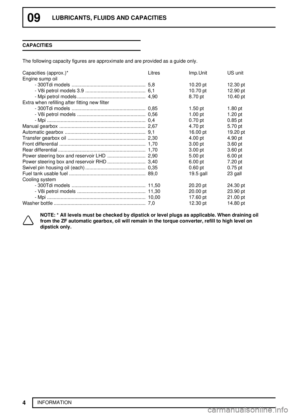
The following capacity figures are approximate and are provided as a guide only.
Capacities (approx.)* Litres Imp.Unit US unit
Engine sump oil
- 300Tdi models 5,8...................................................... 10.20 pt 12.30 pt
- V8i petrol models 3.9 6,1............................................ 10.70 pt 12.90 pt
- Mpi petrol models 4,90.................................................. 8.70 pt 10.40 pt
Extra when refilling after fitting new filter
- 300Tdi models 0,85...................................................... 1.50 pt 1.80 pt
- V8i petrol models 0,56.................................................. 1.00 pt 1.20 pt
- Mpi 0,4........................................................................ 0.70 pt 0.85 pt
Manual gearbox 2,67............................................................... 4.70 pt 5.70 pt
Automatic gearbox 9,1........................................................... 16.00 pt 19.20 pt
Transfer gearbox oil 2,30......................................................... 4.00 pt 4.90 pt
Front differential 1,70............................................................... 3.00 pt 3.60 pt
Rear differential 1,70................................................................ 3.00 pt 3.60 pt
Power steering box and reservoir LHD 2,90............................ 5.00 pt 6.00 pt
Power steering box and reservoir RHD 3,40............................ 6.00 pt 7.20 pt
Swivel pin housing oil (each) 0,35............................................ 0.60 pt 0.75 pt
Fuel tank usable fuel 89,0........................................................ 19.5 gall 23 gall
Cooling system
- 300Tdi models 11,50...................................................... 20.20 pt 24.30 pt
- V8i petrol models 11,30.................................................. 20.00 pt 23.90 pt
- Mpi 10,00........................................................................ 17.60 pt 21.00 pt
Washer bottle 7,0................................................................... 12.30 pt 14.80 pt
NOTE: * All levels must be checked by dipstick or level plugs as applicable. When draining oil
from the ZF automatic gearbox, oil will remain in the torque converter, refill to high level on
dipstick only.
Page 65 of 976

MAINTENANCE
3
MAINTENANCE VEHICLE EXTERIOR
CHECK/ADJUST HEADLAMP ALIGNMENT
Check/adjust headlamp and auxiliary alignment.
CHECK FRONT WHEEL ALIGNMENT
Use recognised wheel alignment equipment to
perform this check and adjustment.
See STEERING,
Adjustment, Front Wheel Alignment
REMOVE WHEELS, CHECK TYRES
Check tyres (including spare) for compliance with
manufacturers' specification.
Check visually for cuts, lumps, bulges, uneven tread
wear and tread depth. Check road wheels for
damage.
Check/adjust tyre pressures.
CHECK/TIGHTEN TOWING BRACKET FITTINGSINSPECT BRAKE PADS FOR WEAR, CALIPERS
FOR LEAKS AND CONDITION
Check thickness of brake pads, fit new pads if
minimum thickness is less than 3,0mm. Check brake
pads for oil contamination. If new brake pads required.
See BRAKES, Repair, Front Brake Pads
or.See BRAKES, Repair, Rear Brake Pads
WARNING: When renewing brake pads, it
is essential that only genuine components
with correct grade of lining are used.
Always fit new pads as complete axle sets, NEVER
individually or as a single wheel set. Serious
consequences could result from out of balance
braking due to mixing of linings.
Refit road wheels
Fit road wheels in original hub position. Secure in
position with wheel nuts, do not fully tighten wheel
nuts at this stage, lower vehicle and finally tighten
wheel nuts to correct torque.
Alloy wheels:
130 Nm.
Steel wheels:130 Nm.
LUBRICATE ALL HINGES, DOOR CHECK
MECHANISMS, BONNET [HOOD] CATCHES AND
FUEL FILLER FLAP
Page 83 of 976

12ENGINE
2
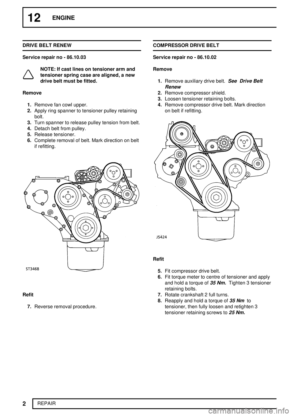
REPAIR DRIVE BELT RENEW
Service repair no - 86.10.03
NOTE: If cast lines on tensioner arm and
tensioner spring case are aligned, a new
drive belt must be fitted.
Remove
1.Remove fan cowl upper.
2.Apply ring spanner to tensioner pulley retaining
bolt.
3.Turn spanner to release pulley tension from belt.
4.Detach belt from pulley.
5.Release tensioner.
6.Complete removal of belt. Mark direction on belt
if refitting.
Refit
7.Reverse removal procedure.COMPRESSOR DRIVE BELT
Service repair no - 86.10.02
Remove
1.Remove auxiliary drive belt.
See Drive Belt
Renew
2.Remove compressor shield.
3.Loosen tensioner retaining bolts.
4.Remove compressor drive belt. Mark direction
on belt if refitting.
Refit
5.Fit compressor drive belt.
6.Fit torque meter to centre of tensioner and apply
and hold a torque of
35 Nm.Tighten 3 tensioner
retaining bolts.
7.Rotate crankshaft 2 full turns.
8.Reapply and hold a torque of
35 Nmto
tensioner, then fully loosen and retighten 3
tensioner retaining screws to
25 Nm.
Page 85 of 976

12ENGINE
4
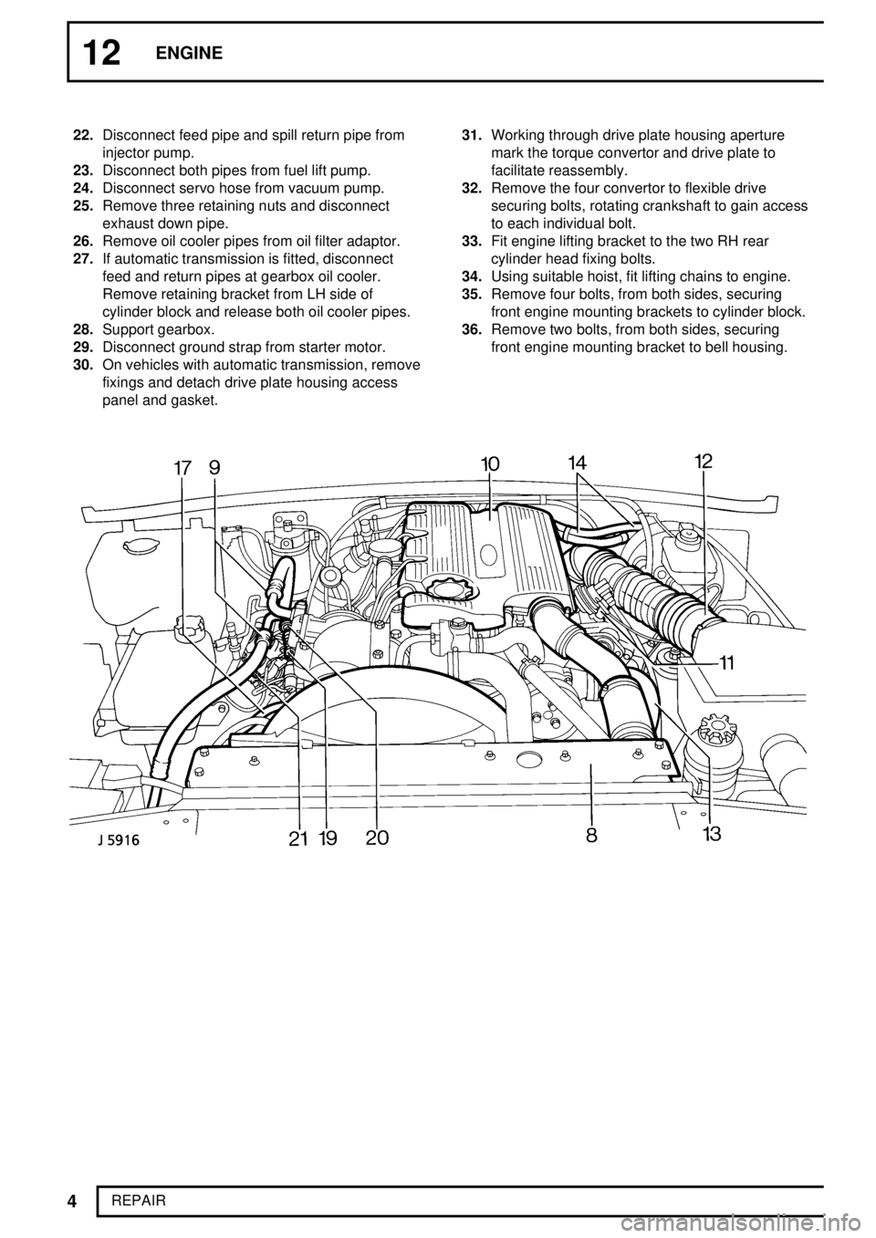
REPAIR 22.Disconnect feed pipe and spill return pipe from
injector pump.
23.Disconnect both pipes from fuel lift pump.
24.Disconnect servo hose from vacuum pump.
25.Remove three retaining nuts and disconnect
exhaust down pipe.
26.Remove oil cooler pipes from oil filter adaptor.
27.If automatic transmission is fitted, disconnect
feed and return pipes at gearbox oil cooler.
Remove retaining bracket from LH side of
cylinder block and release both oil cooler pipes.
28.Support gearbox.
29.Disconnect ground strap from starter motor.
30.On vehicles with automatic transmission, remove
fixings and detach drive plate housing access
panel and gasket.31.Working through drive plate housing aperture
mark the torque convertor and drive plate to
facilitate reassembly.
32.Remove the four convertor to flexible drive
securing bolts, rotating crankshaft to gain access
to each individual bolt.
33.Fit engine lifting bracket to the two RH rear
cylinder head fixing bolts.
34.Using suitable hoist, fit lifting chains to engine.
35.Remove four bolts, from both sides, securing
front engine mounting brackets to cylinder block.
36.Remove two bolts, from both sides, securing
front engine mounting bracket to bell housing.
Page 86 of 976

Tdi
5
REPAIR
37.Remove nuts and plain washers securing front
engine mountings to chassis,and lift both engine
mounting bracket assemblies from vehicle.
38.Remove engine to bell housing fixings. Leave
starter motor attached.
39.Raise engine to separate from transmission.
40.Check all connections to engine have been
disconnected.
41.Remove engine.Refit
42.Apply Hylomar to mating faces of bell housing.
Lubricate splines of gearbox primary pinion with
Rocol MV 3.
If automatic transmission, coat the four drive
plate to torque convertor bolts with Loctite 290.
Tighten to
39 Nm.
43.Lower engine and locate with transmission.
If manual transmission locate primary pinion into
clutch and engage bell housing dowels. Fit
engine to bell housing fixings. Tighten to
40 Nm.
If automatic transmission fixings. Tighten to46
Nm.
44.Raise engine, refit front engine mounting
brackets to cylinder block and bell housing.
45.Remove gearbox support and lower engine.
46.Tighten front engine mountings to chassis
fixings. Tighten to
45 Nm.
47.Reverse removal procedure. 1 to 37.
Page 92 of 976

Tdi
11
REPAIR Timing belt fitting and tensioning
NOTE: It is important that belt tensioning
is carried out carefully and accurately. The
following procedure involves tensioning
the belt twice to ensure that it is equally tensioned
between each gear. New and original belts are
tensioned to different figures.
28.Ensure timing marks are correctly aligned, pin
from special tool LRT-12-045 is correctly
inserted in injection pump gear and timing tool
LRT-12-044 (LRT-12-085 if EDC) is fitted to
flywheel housing with pin located in flywheel slot.
Or if automatic: Timing tool LRT-12-044 is fitted
to engine backplate and pin located in ring gear.
29.Fit belt observing rotational marks made during
removal. Feed belt over gears keeping it tight on
drive side.
30.Fit idler pulley.
31.Slacken injection pump gear retaining bolts.
32.Adjust belt to correctly sit in gears.
33.Slacken belt tensioner securing bolt to finger
tight.
34.Insert 13 mm square drive extension bar in
tensioner plate.
NOTE: Belt tensioning should be carried
out using a dial type torque meter having a
range not exceeding
60 Nm.The torque
meter should be used in the almost vertical
position.
35.Apply a tension of
14 to 16 Nmfor a new belt or
11 to 13 Nmfor an original belt. When tension
is correct tighten clamp bolt.
36.Tighten injection pump gear bolts.
37.Remove pin from injection pump gear.
38.Disengage timing pin from timing slot in flywheel
or ring gear.
39.Rotate crankshaft one and three quarter turns in
a clockwise direction; then continue rotation until
timing pin in timing tool can be engaged with slot
in flywheel or ring gear.
40.Disengage timing pin.
41.Insert pin from special tool LRT-12-045 in
injection pump gear and through into pump
flange.
42.Slacken injection pump gear retaining bolts.
43.Slacken tensioner and retension belt.
44.Tighten injection pump gear retaining bolts.
45.Remove pin from injection pump gear.
46.Remove timing tool and refit plug.
47.Fit front cover plate using new gaskets.
See
Front Cover Plate
Page 97 of 976

12ENGINE
16
REPAIR 8.Ensure housing seal is correctly seated in its
groove in new housing and seal assembly.
9.Fit new assembly, with former/guide in-situ, over
crankshaft flange, this action will eject
former/guide.
10.Secure assembly to cylinder block with five bolts
tightened to correct torque, removing slave studs
individually and inserting bolts.
11.Refit flywheel.
See Flywheel
12.Refit clutch.See CLUTCH, Repair, Clutch
Assembly
13.Refit gearbox.See MANUAL GEARBOX,
Repair, R380 Manual Gearbox
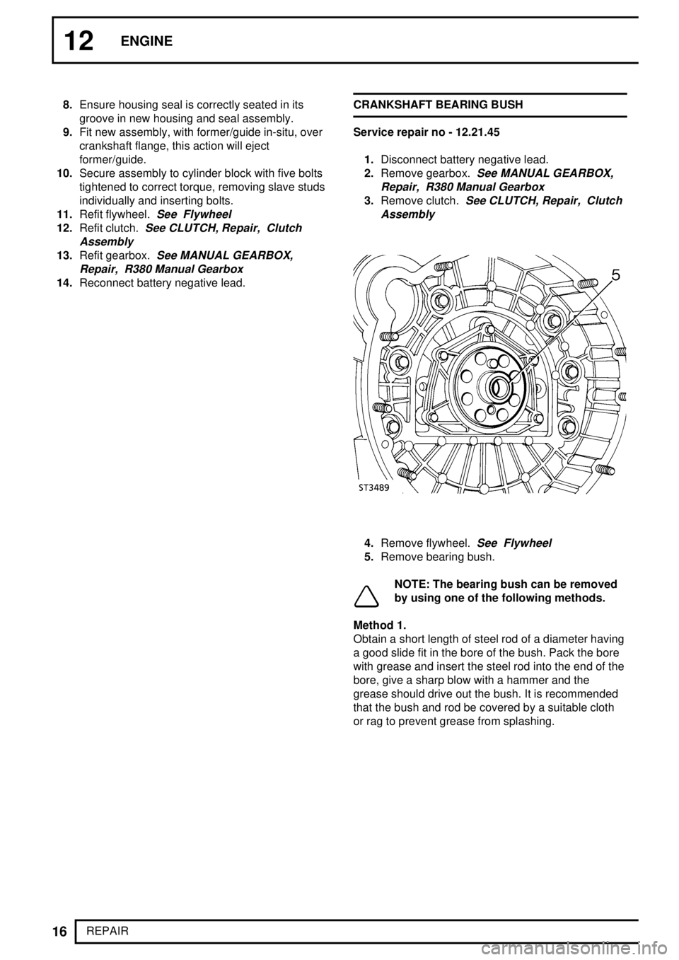
14.Reconnect battery negative lead.CRANKSHAFT BEARING BUSH
Service repair no - 12.21.45
1.Disconnect battery negative lead.
2.Remove gearbox.
See MANUAL GEARBOX,
Repair, R380 Manual Gearbox
3.Remove clutch.See CLUTCH, Repair, Clutch
Assembly
4.Remove flywheel.See Flywheel
5.Remove bearing bush.
NOTE: The bearing bush can be removed
by using one of the following methods.
Method 1.
Obtain a short length of steel rod of a diameter having
a good slide fit in the bore of the bush. Pack the bore
with grease and insert the steel rod into the end of the
bore, give a sharp blow with a hammer and the
grease should drive out the bush. It is recommended
that the bush and rod be covered by a suitable cloth
or rag to prevent grease from splashing.