1995 JEEP YJ wheel bolt torque
[x] Cancel search: wheel bolt torquePage 1567 of 2158
(21) Remove clutch release bearing, release fork
and retainer clip.
(22) Remove clutch housing from transmission.
TRANSMISSION INSTALLATION
(1) Install clutch housing on transmission. Tighten
housing bolts to 37 Nzm (27 ft. lbs.) torque.
(2) Lubricate contact surfaces of release fork pivot
ball stud and release fork with high temp grease.
Then install release bearing, fork and retainer clip.
(3) Mount transmission on transmission jack.
(4) Lightly lubricate pilot bearing and transmis-
sion input shaft splines with Mopar high temp
grease.
(5) Align transmission input shaft, release bearing,
and clutch disc splines. Then slide transmission into
place.
(6) Install and tighten clutch housing-to-engine
bolts to 38 Nzm (28 ft. lbs.) torque.Be sure the
housing is properly seated on engine block be-
fore tightening bolts.
(7) Lower transmission approximately 7-8 cm (3
in.) for access to shift tower. Be sure transmission is
in first or third gear.
(8) Reach up and around transmission and insert
shift lever in shift tower. Press lever retainer down-
ward and turn it clockwise to lock it in place. Then
install lever dust boot on shift tower.
(9) Install slave cylinder in clutch housing.
(10) Align and install transfer case on and trans-
mission. Tighten transfer case-to-transmission nuts
to 35 Nzm (26 ft. lbs.) torque.
(11) Connect transfer case vent hose and shift link-
age. Check and adjust linkage if necessary.
(12) Connect transfer case vent hose.
(13) Secure wire harnesses in clips/tie straps on
transmission and transfer case.
(14) Connect backup light switch wires.
(15) Connect vehicle speed sensor wires.
(16) Install and connect crankshaft position sensor.
(17) Install rear crossmember (Fig. 5). On XJ,
tighten crossmember-to-frame bolts to 41 Nzm (31 ft.
lbs.) torque. Then tighten transmission-to-rear sup-
port bolts/nuts to 45 Nzm (33 ft. lbs.) torque. On YJ,
tighten bolts/nuts to indicated torque (Fig. 5).
(18) Remove jack stand.
(19) Align and install front/rear propeller shafts.
Tighten shaft U-joint clamp bolts to 19 Nzm (170 in.
lbs.) torque.
(20) Install skid plate, if equipped. Tighten bolts to
42 Nzm (31 ft. lbs.) torque. Tighten stud nuts to 17
Nzm (150 in. lbs.) torque.
(21) Top off transmission and transfer case lubri-
cant levels.
(22) Lower vehicle.
TRANSMISSION DISASSEMBLY AND OVERHAUL
ADAPTER HOUSING AND FRONT BEARING
RETAINER REMOVAL
(1) Drain transmission lubricant.
(2) Remove release bearing and lever.
(3) Remove clutch housing bolts and remove hous-
ing.
(4) On 2-wheel drive models, remove vehicle speed
sensor, speedometer adapter and speedometer driven
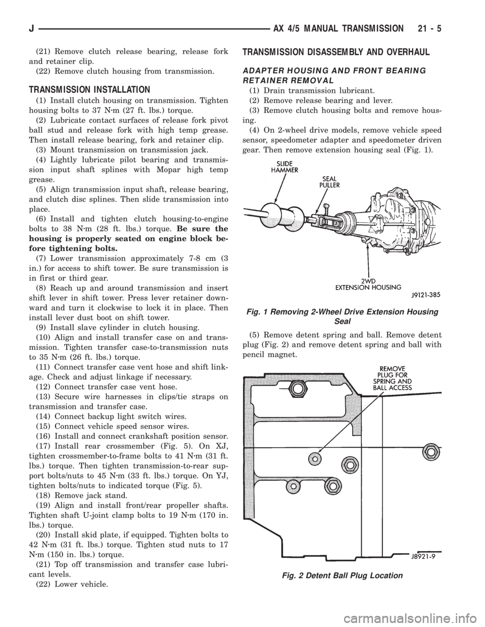
gear. Then remove extension housing seal (Fig. 1).
(5) Remove detent spring and ball. Remove detent
plug (Fig. 2) and remove detent spring and ball with
pencil magnet.
Fig. 1 Removing 2-Wheel Drive Extension Housing
Seal
Fig. 2 Detent Ball Plug Location
JAX 4/5 MANUAL TRANSMISSION 21 - 5
Page 1594 of 2158
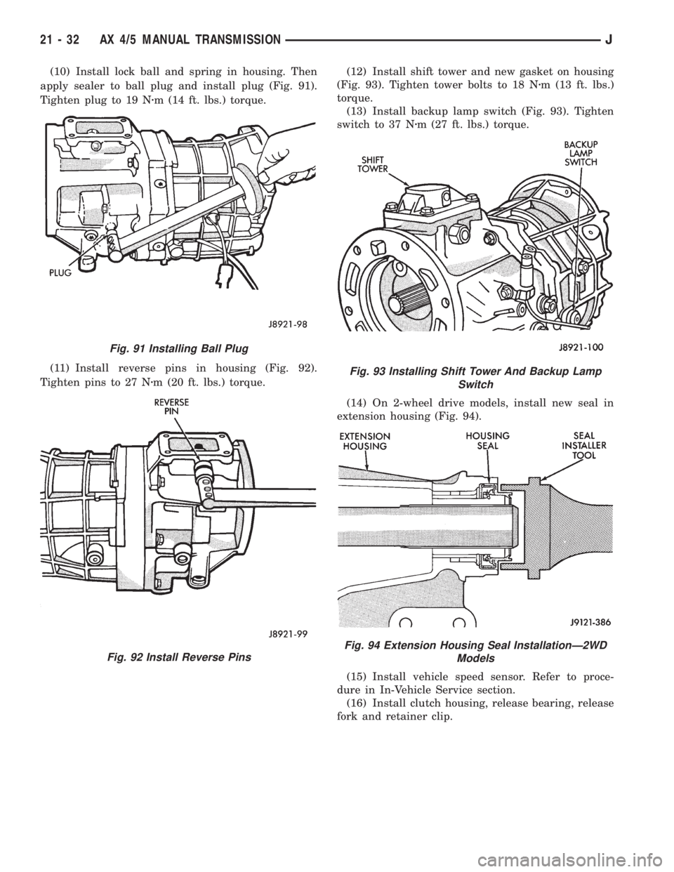
(10) Install lock ball and spring in housing. Then
apply sealer to ball plug and install plug (Fig. 91).
Tighten plug to 19 Nzm (14 ft. lbs.) torque.
(11) Install reverse pins in housing (Fig. 92).
Tighten pins to 27 Nzm (20 ft. lbs.) torque.(12) Install shift tower and new gasket on housing
(Fig. 93). Tighten tower bolts to 18 Nzm (13 ft. lbs.)
torque.
(13) Install backup lamp switch (Fig. 93). Tighten
switch to 37 Nzm (27 ft. lbs.) torque.
(14) On 2-wheel drive models, install new seal in
extension housing (Fig. 94).
(15) Install vehicle speed sensor. Refer to proce-
dure in In-Vehicle Service section.
(16) Install clutch housing, release bearing, release
fork and retainer clip.
Fig. 91 Installing Ball Plug
Fig. 92 Install Reverse Pins
Fig. 93 Installing Shift Tower And Backup Lamp
Switch
Fig. 94 Extension Housing Seal InstallationÐ2WD
Models
21 - 32 AX 4/5 MANUAL TRANSMISSIONJ
Page 1912 of 2158
WHEELS
GENERAL INFORMATION
Original equipment wheels are designed for the
specified Maximum Vehicle Capacity.
All models use steel or cast aluminum drop center
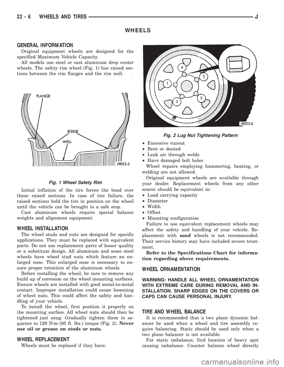
wheels. The safety rim wheel (Fig. 1) has raised sec-
tions between the rim flanges and the rim well.
Initial inflation of the tire forces the bead over
these raised sections. In case of tire failure, the
raised sections hold the tire in position on the wheel
until the vehicle can be brought to a safe stop.
Cast aluminum wheels require special balance
weights and alignment equipment.
WHEEL INSTALLATION
The wheel studs and nuts are designed for specific
applications. They must be replaced with equivalent
parts. Do not use replacement parts of lesser quality
or a substitute design. All aluminum and some steel
wheels have wheel stud nuts which feature an en-
larged nose. This enlarged nose is necessary to en-
sure proper retention of the aluminum wheels.
Before installing the wheel, be sure to remove any
build up of corrosion on the wheel mounting surfaces.
Ensure wheels are installed with good metal-to-metal
contact. Improper installation could cause loosening
of wheel nuts. This could affect the safety and han-
dling of your vehicle.
To install the wheel, first position it properly on
the mounting surface. All wheel nuts should then be
tightened just snug. Gradually tighten them in se-
quence to 129 Nzm (95 ft. lbs.) torque (Fig. 2).Never
use oil or grease on studs or nuts.
WHEEL REPLACEMENT
Wheels must be replaced if they have:²Excessive runout
²Bent or dented
²Leak air through welds
²Have damaged bolt holes
Wheel repairs employing hammering, heating, or
welding are not allowed.
Original equipment wheels are available through
your dealer. Replacement wheels from any other
source should be equivalent in:
²Load carrying capacity
²Diameter
²Width
²Offset
²Mounting configuration
Failure to use equivalent replacement wheels may
affect the safety and handling of your vehicle. Re-
placement withusedwheels is not recommended.
Their service history may have included severe treat-
ment.
Refer to the Specifications Chart for informa-
tion regarding above requirements.
WHEEL ORNAMENTATION
WARNING: HANDLE ALL WHEEL ORNAMENTATION
WITH EXTREME CARE DURING REMOVAL AND IN-
STALLATION. SHARP EDGES ON THE COVERS OR
CAPS CAN CAUSE PERSONAL INJURY.
TIRE AND WHEEL BALANCE
It is recommended that a two plane dynamic bal-
ancer be used when a wheel and tire assembly re-
quire balancing. Static should be used only when a
two plane balancer is not available.
For static imbalance, find location of heavy spot
causing imbalance. Counter balance wheel directly
Fig. 1 Wheel Safety Rim
Fig. 2 Lug Nut Tightening Pattern
22 - 6 WHEELS AND TIRESJ
Page 2001 of 2158
INSTALLATION
(1) Position the replacement cover on the cushion.
(2) Compress the cover and attach the retaining
clips to the front and rear wire retainers.
(3) Install the serrated retainers at the ends of the
cover.
(4) Install the seat cushion in the vehicle. If neces-
sary, refer to the installation procedure.
REAR SEATBACKÐXJ
REMOVAL
(1) Disengage the seat cushion at the rear by pull-
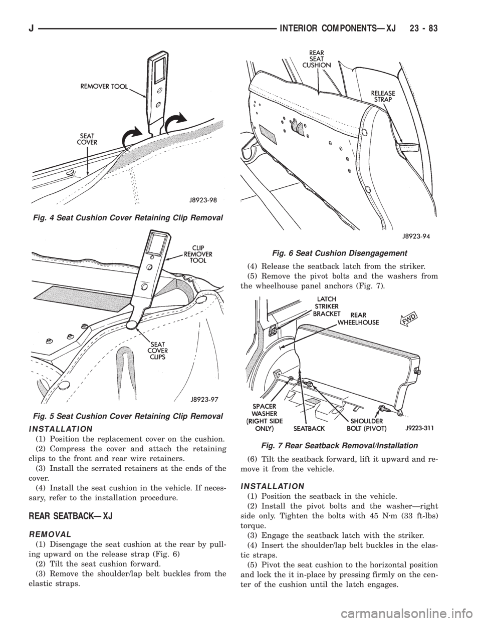
ing upward on the release strap (Fig. 6)
(2) Tilt the seat cushion forward.
(3) Remove the shoulder/lap belt buckles from the
elastic straps.(4) Release the seatback latch from the striker.
(5) Remove the pivot bolts and the washers from
the wheelhouse panel anchors (Fig. 7).
(6) Tilt the seatback forward, lift it upward and re-
move it from the vehicle.
INSTALLATION
(1) Position the seatback in the vehicle.
(2) Install the pivot bolts and the washerÐright
side only. Tighten the bolts with 45 Nzm (33 ft-lbs)
torque.
(3) Engage the seatback latch with the striker.
(4) Insert the shoulder/lap belt buckles in the elas-
tic straps.
(5) Pivot the seat cushion to the horizontal position
and lock the it in-place by pressing firmly on the cen-
ter of the cushion until the latch engages.
Fig. 4 Seat Cushion Cover Retaining Clip Removal
Fig. 5 Seat Cushion Cover Retaining Clip Removal
Fig. 6 Seat Cushion Disengagement
Fig. 7 Rear Seatback Removal/Installation
JINTERIOR COMPONENTSÐXJ 23 - 83
Page 2016 of 2158
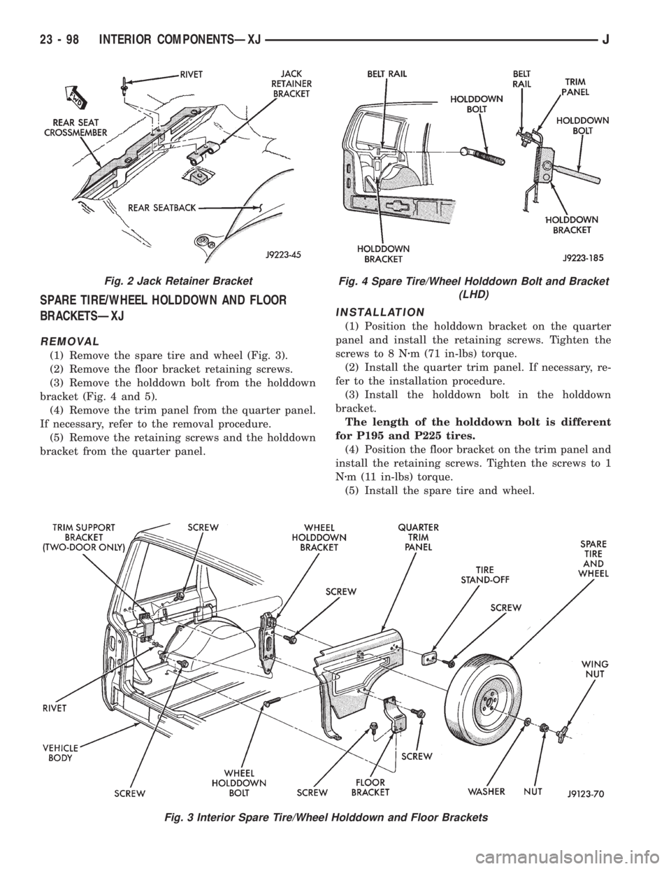
SPARE TIRE/WHEEL HOLDDOWN AND FLOOR
BRACKETSÐXJ
REMOVAL
(1) Remove the spare tire and wheel (Fig. 3).
(2) Remove the floor bracket retaining screws.
(3) Remove the holddown bolt from the holddown
bracket (Fig. 4 and 5).
(4) Remove the trim panel from the quarter panel.
If necessary, refer to the removal procedure.
(5) Remove the retaining screws and the holddown
bracket from the quarter panel.
INSTALLATION
(1) Position the holddown bracket on the quarter
panel and install the retaining screws. Tighten the
screws to 8 Nzm (71 in-lbs) torque.
(2) Install the quarter trim panel. If necessary, re-
fer to the installation procedure.
(3) Install the holddown bolt in the holddown
bracket.
The length of the holddown bolt is different
for P195 and P225 tires.
(4) Position the floor bracket on the trim panel and
install the retaining screws. Tighten the screws to 1
Nzm (11 in-lbs) torque.
(5) Install the spare tire and wheel.
Fig. 3 Interior Spare Tire/Wheel Holddown and Floor Brackets
Fig. 2 Jack Retainer BracketFig. 4 Spare Tire/Wheel Holddown Bolt and Bracket
(LHD)
23 - 98 INTERIOR COMPONENTSÐXJJ
Page 2033 of 2158
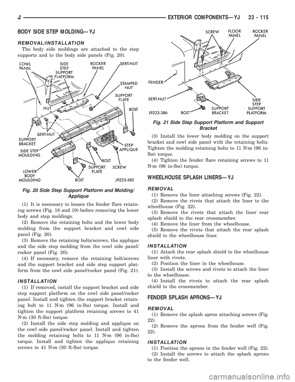
BODY SIDE STEP MOLDINGÐYJ
REMOVAL/INSTALLATION
The body side moldings are attached to the step
supports and to the body side panels (Fig. 20).
(1) It is necessary to loosen the fender flare retain-
ing screws (Fig. 18 and 19) before removing the lower
body and step moldings.
(2) Remove the retaining bolts and the lower body
molding from the support bracket and cowl side
panel (Fig. 20).
(3) Remove the retaining bolts/screws, the applique
and the side step molding from the cowl side panel/
rocker panel (Fig. 20).
(4) If necessary, remove the retaining bolt/screws
and the support bracket and side step support plat-
form from the cowl side panel/rocker panel (Fig. 21).
INSTALLATION
(1) If removed, install the support bracket and side
step support platform on the cowl side panel/rocker
panel. Install and tighten the support bracket retain-
ing bolt to 11 Nzm (96 in-lbs) torque. Install and
tighten the support platform retaining screws to 41
Nzm (30 ft-lbs) torque.
(2) Install the side step molding and applique on
the cowl side panel/rocker panel. Install and tighten
the molding retaining bolts to 11 Nzm (96 in-lbs)
torque. Install and tighten the applique retaining
screws to 41 Nzm (30 ft-lbs) torque.(3) Install the lower body molding on the support
bracket and cowl side panel with the retaining bolts.
Tighten the molding retaining bolts to 11 Nzm (96 in-
lbs) torque.
(4) Tighten the fender flare retaining screws to 11
Nzm (96 in-lbs) torque.
WHEELHOUSE SPLASH LINERSÐYJ
REMOVAL
(1) Remove the liner attaching screws (Fig. 22).
(2) Remove the rivets that attach the liner to the
wheelhouse (Fig. 22).
(3) Remove the rivets that attach the liner rear
splash shield to the rear crossmember.
(4) Remove the liner from the wheelhouse.
(5) Remove the rivets that attach the rear splash
shield to the wheelhouse liner.
INSTALLATION
(1) Attach the rear splash shield to the wheelhouse
liner with rivets.
(2) Position the liner in the wheelhouse.
(3) Install the screws and rivets to attach the liner
to the wheelhouse.
(4) Install the rivets to attach the rear splash
shield to the crossmember.
FENDER SPLASH APRONSÐYJ
REMOVAL
(1) Remove the splash apron attaching screws (Fig.
22).
(2) Remove the aprons from the fender well (Fig.
22).
INSTALLATION
(1) Position the aprons in the fender well (Fig. 22).
(2) Install the screws to attach the splash aprons
to the fender well.
Fig. 20 Side Step Support Platform and Molding/
Applique
Fig. 21 Side Step Support Platform and Support
Bracket
JEXTERIOR COMPONENTSÐYJ 23 - 115
Page 2050 of 2158
channel. Close the rear window curtain zippers and
attach the side snap-on retainers.
(16) Attach all the top cover snap-on retainers to
the upper side retainers located above both doors. As
necessary, slide the mating half of the snap-on re-
tainers so that they will align with the snap-on re-
tainers on the top cover. Tuck the edge of the top
cover inside the side retainer.
(17) Install the door windows by inserting the re-
tainers into the door grommets. Attach the snap-on
retainers located along the bottom edge of the win-
dow to the door retainer.
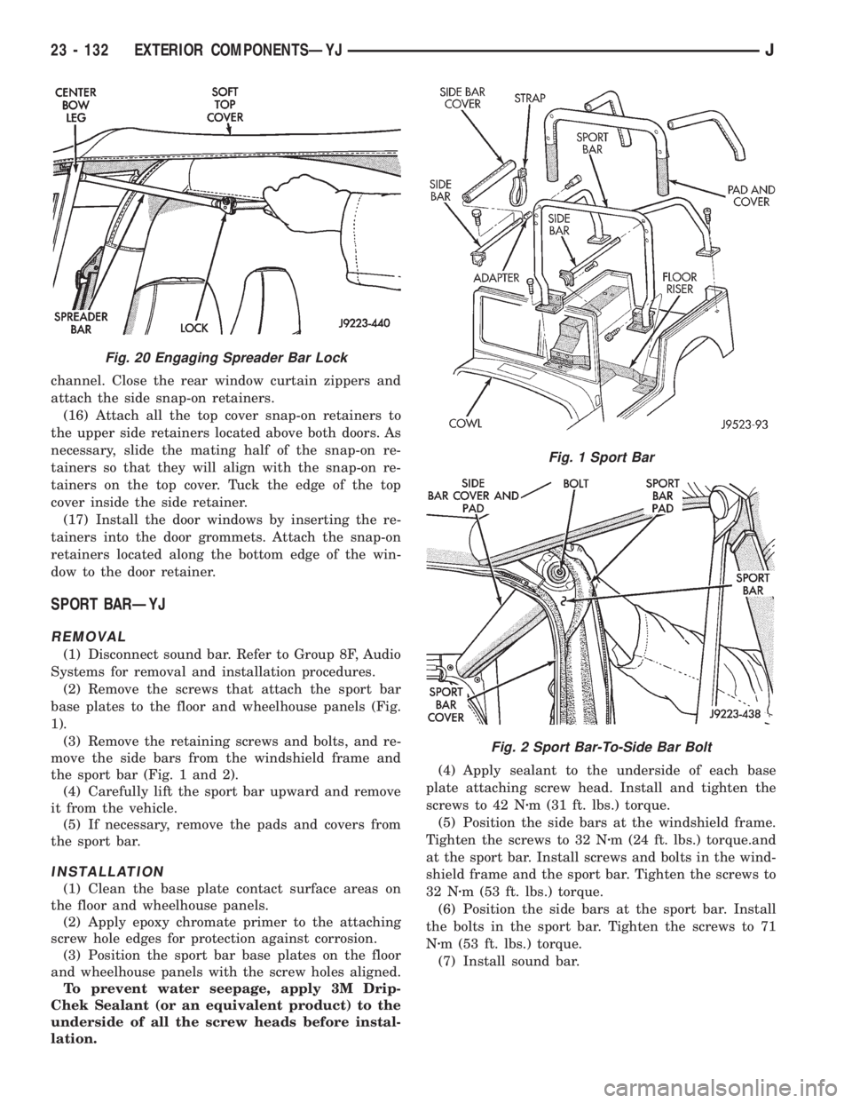
SPORT BARÐYJ
REMOVAL
(1) Disconnect sound bar. Refer to Group 8F, Audio
Systems for removal and installation procedures.
(2) Remove the screws that attach the sport bar
base plates to the floor and wheelhouse panels (Fig.
1).
(3) Remove the retaining screws and bolts, and re-
move the side bars from the windshield frame and
the sport bar (Fig. 1 and 2).
(4) Carefully lift the sport bar upward and remove
it from the vehicle.
(5) If necessary, remove the pads and covers from
the sport bar.
INSTALLATION
(1) Clean the base plate contact surface areas on
the floor and wheelhouse panels.
(2) Apply epoxy chromate primer to the attaching
screw hole edges for protection against corrosion.
(3) Position the sport bar base plates on the floor
and wheelhouse panels with the screw holes aligned.
To prevent water seepage, apply 3M Drip-
Chek Sealant (or an equivalent product) to the
underside of all the screw heads before instal-
lation.(4) Apply sealant to the underside of each base
plate attaching screw head. Install and tighten the
screws to 42 Nzm (31 ft. lbs.) torque.
(5) Position the side bars at the windshield frame.
Tighten the screws to 32 Nzm (24 ft. lbs.) torque.and
at the sport bar. Install screws and bolts in the wind-
shield frame and the sport bar. Tighten the screws to
32 Nzm (53 ft. lbs.) torque.
(6) Position the side bars at the sport bar. Install
the bolts in the sport bar. Tighten the screws to 71
Nzm (53 ft. lbs.) torque.
(7) Install sound bar.
Fig. 20 Engaging Spreader Bar Lock
Fig. 1 Sport Bar
Fig. 2 Sport Bar-To-Side Bar Bolt
23 - 132 EXTERIOR COMPONENTSÐYJJ
Page 2127 of 2158
BELT TENSIONERÐXJ MODELS WITH
RIGHT HAND DRIVE, AUTOMATIC........7-42
BELT TENSIONÐEXCEPT RIGHT HAND
DRIVE (RHD).........................7-38
BELT TENSIONÐEXCEPT RIGHT HAND
DRIVE (RHD) MODELS.................7-45
BELT TENSIONÐRIGHT HAND DRIVE
(RHD)..............................7-38
BELT/BUCKLEÐXJ, FRONT SHOULDER . . . 23-90
BELT/BUCKLEÐXJ, REAR SHOULDER/
LAP ...............................23-91
BELTLINE SEALÐYJ.................23-142
BELTS, ENGINE ACCESSORY DRIVE.......7-38
BELTSÐYJ, FRONT SHOULDER........23-154
BELTSÐYJ, REAR SHOULDER.........23-154
BENCH BLEEDING, MASTER CYLINDER....5-21
BENCH, GEAR ADJUSTMENTS ON.......19-44
BENCH SEATÐYJ, REAR..............23-153
BEZELÐXJ, INSTRUMENT CLUSTER.....23-80
BEZELÐYJ, INSTRUMENT CLUSTER....23-151
BIN REMOVE/INSTALL, SUNGLASSES
STORAGE...........................8C-7
BLADE REMOVE/INSTALL, WINDSHIELD
WIPER.............................8K-17
BLEEDING, MASTER CYLINDER BENCH....5-21
BLEEDING RECOMMENDATIONS, BRAKE . . . 5-10
BLEEDING (WITH ABS BRAKES), BRAKE . . . 5-11
BLEEDING (WITH STANDARD BRAKES),
BRAKE..............................5-11
BLEEDINGÐBRAKELINES AND HOSES,
BRAKE FLUIDÐBRAKE.................5-10
BLOCK, CYLINDER................9-49,9-91
BLOCK HEATER, ENGINE................7-44
BLOCKSÐTWO-DOOR VEHICLES, FRONT
DOOR SPACER......................23-53
BLOWER MOTOR; AIR CONDITIONING/
HEATER (XJ)......................8W-42-1
BLOWER MOTOR; AIR CONDITIONING/
HEATER (XJ-RHD)..................8W-42-1
BLOWER MOTOR; HEATING AND AIR
CONDITIONING......................24-17
BLOWER MOTOR, A/C.................24-35
BLOWER MOTOR, A/C-HEATER; AIR
CONDITIONING/HEATER (YJ).........8W-42-2
BLOWER MOTOR (HEATING)...........24-33
BLOWER MOTOR RESISTORS
REPLACEMENT......................24-31
BLOWER MOTOR SWITCH.............24-16
BLOWER MOTOR/AIR DOOR MOTOR
SWITCH REPLACEMENT...............24-32
BLOWER MOTOR/FAN REPLACEMENT....24-24
BODY ASSEMBLY AND ADJUSTMENT,
VALVE ............................21-153
BODY CHECK BALL DIMENSIONS, AW-4
VALVE ............................21-341
BODY CODE LETTERS, JEEP..............5-2
BODY LUBRICANT SPECIFICATIONS.......0-33
BODY OVERHAUL, TRANSMISSION
VALVE ............................21-250
BODY REMOVAL, TRANSMISSION VALVE . 21-186
BODY REMOVAL, VALVE..............21-104
BODY SERVICE INFORMATION, GENERAL . . 23-1
BODY SERVICE, VALVE...............21-104
BODY SIDE MOLDING/CLADDINGÐXJ....23-20
BODY SIDE STEP MOLDINGÐYJ.......23-115
BODY SOLENOIDS, TRANSMISSION
VALVE ............................21-184
BODY STRIPES/DECALSÐXJ...........23-21
BODY STRIPES/DECALSÐYJ..........23-116
BODY, THROTTLE...............14-33,14-64
BOLT IDENTIFICATION..............Intro.-14
BOLT STRENGTH..................Intro.-15
BOOSTER CHECK VALVE TEST, POWER.....5-9
BOOSTER INSTALLATION (XJ WITH
ABS), POWER BRAKE..................5-27
BOOSTER INSTALLATION (XJ WITHOUT
ABS), POWER BRAKE..................5-30
BOOSTER INSTALLATION (YJ), POWER
BRAKE..............................5-30
BOOSTER, MASTER CYLINDER/POWER
BRAKE
..............................5-34
BOOSTER OPERATION, POWER BRAKE
....5-23
BOOSTER REMOVAL (XJ WITH ABS),
POWER BRAKE
.......................5-24
BOOSTER REMOVAL (XJ WITHOUT ABS),
POWER BRAKE
.......................5-29
BOOSTER REMOVAL (YJ), POWER
BRAKE
..............................5-30BOOSTER TEST, MASTER CYLINDER/
POWER..............................5-8
BOOSTER VACUUM TEST, POWER.........5-9
BOOSTERÐBRAKE PEDALÐ
BRAKELIGHT SWITCH, POWER BRAKE....5-22
BORES, HONING CYLINDER..............9-2
BOX LAMP, GLOVE; INTERIOR LIGHTING
(XJ).............................8W-44-1
BOX LAMP, GLOVE; INTERIOR LIGHTING
(XJ-RHD).........................8W-44-1
BOXÐYJ, GLOVE...................23-152
BRACKET REPLACEMENTÐXJ, INTERIOR
REARVIEW MIRROR SUPPORT..........23-68
BRACKETÐYJ, REARVIEW MIRROR
RETAINING........................23-144
BRACKETSÐXJ, SPARE TIRE/WHEEL
HOLDDOWN AND FLOOR..............23-98
BRAKE ADJUSTMENT, DRUM............5-57
BRAKE BLEEDING RECOMMENDATIONS....5-10
BRAKE BLEEDING (WITH ABS BRAKES)....5-11
BRAKE BLEEDING (WITH STANDARD
BRAKES)............................5-11
BRAKE BOOSTER INSTALLATION (XJ
WITH ABS), POWER...................5-27
BRAKE BOOSTER INSTALLATION (XJ
WITHOUT ABS), POWER................5-30
BRAKE BOOSTER INSTALLATION (YJ),
POWER.............................5-30
BRAKE BOOSTER, MASTER CYLINDER/
POWER.............................5-34
BRAKE BOOSTER OPERATION, POWER....5-23
BRAKE BOOSTER REMOVAL (XJ WITH
ABS), POWER........................5-24
BRAKE BOOSTER REMOVAL (XJ
WITHOUT ABS), POWER................5-29
BRAKE BOOSTER REMOVAL (YJ),
POWER.............................5-30
BRAKE BOOSTERÐBRAKE PEDALÐ
BRAKELIGHT SWITCH, POWER...........5-22
BRAKE CABLE TENSIONER ADJUSTMENT
(XJ/YJ), PARKING.....................5-69
BRAKE CABLE TENSIONER
REPLACEMENT (XJ), PARKING...........5-66
BRAKE CHECK, PRELIMINARY............5-4
BRAKE COMPONENTS...................5-1
BRAKE DIAGNOSIS, ABS.................5-3
BRAKE DIAGNOSIS, SERVICE.............5-4
BRAKE DRUM REFINISHING.............5-58
BRAKE FLUID CONTAMINATION.......5-10,5-7
BRAKE FLUID LEVEL...................5-10
BRAKE FLUID, RECOMMENDED..........5-10
BRAKE FLUID/LUBRICANTS/CLEANING
SOLVENTS............................5-2
BRAKE FLUIDÐBRAKE BLEEDINGÐ
BRAKELINES AND HOSES...............5-10
BRAKE FRONT CABLE REPLACEMENT
(YJ), PARKING........................5-67
BRAKE HANDLE COVERÐXJ, PARKING . . . 23-94
BRAKE LEVER INSTALLATION (XJ WITH
FULL CONSOLE), PARKING..............5-64
BRAKE LEVER INSTALLATION (XJ WITH
MINI CONSOLE), PARKING..............5-63
BRAKE LEVER INSTALLATION (XJ
WITHOUT CONSOLE), PARKING..........5-65
BRAKE LEVER REMOVAL (XJ WITH FULL
CONSOLE), PARKING..................5-63
BRAKE LEVER REMOVAL (XJ WITH MINI
CONSOLE), PARKING..................5-62
BRAKE LEVER REMOVAL (XJ WITHOUT
CONSOLE), PARKING
..................5-64
BRAKE MALFUNCTIONS, DIAGNOSING
PARKING
.............................5-8
BRAKE NOISE
.........................5-7
BRAKE OPERATION, PARKING
...........5-60
BRAKE OVERHAUL, SECOND
..........21-241
BRAKE PACK REQUIREMENTS, AW-4
CLUTCH
...........................21-341
BRAKE PEDAL BUSHINGS, CLUTCH
.......0-22
BRAKE PEDAL INSTALLATION
............5-31
BRAKE PEDAL INSTALLATION (YJ),
PARKING
............................5-66
BRAKE PEDAL REMOVAL
...............5-31
BRAKE PEDAL REMOVAL (YJ), PARKING
. . . 5-66
BRAKE PEDAL TRAVEL SENSOR;
ANTI-LOCK BRAKES (YJ)
............8W-32-1
BRAKE PISTON AND TRANSMISSION
CASE OVERHAUL, FIRST-REVERSE
......21-247BRAKE REAR CABLE REPLACEMENT
(XJ), PARKING........................5-67
BRAKE REAR CABLE REPLACEMENT
(YJ), PARKING........................5-68
BRAKE ROTOR REFINISHING, DISC.......5-53
BRAKE ROTOR RUNOUT, DISC...........5-52
BRAKE ROTOR THICKNESS, DISC........5-52
BRAKE SAFETY PRECAUTIONS............5-2
BRAKE SWITCH......................14-59
BRAKE SWITCH INPUT; ANTI-LOCK
BRAKES (XJ)......................8W-32-2
BRAKE SWITCH INPUT; ANTI-LOCK
BRAKES (XJ-RHD).................8W-32-2
BRAKE SWITCH INPUT; ANTI-LOCK
BRAKES (YJ)......................8W-32-2
BRAKE SWITCH INPUT; FUEL/IGNITION
(XJ).............................8W-30-5
BRAKE SWITCH INPUT; FUEL/IGNITION
(YJ).............................8W-30-5
BRAKE SWITCH INPUT; FUEL/IGNITION
(XJ-RHD).........................8W-30-5
BRAKE SWITCH, PARKING..............5-68
BRAKE SWITCHÐPCM INPUT..........14-22
BRAKE SYSTEM, POWER...............0-30
BRAKE TORQUE SPECIFICATIONS.........5-70
BRAKE WARNING LAMP; INSTRUMENT
CLUSTER (XJ).....................8W-40-2
BRAKE WARNING LAMP; INSTRUMENT
CLUSTER (XJ-RHD)................8W-40-2
BRAKE WARNING LAMP; INSTRUMENT
CLUSTER (YJ)......................8W-40-2
BRAKE WARNING LIGHTS................5-1
BRAKELIGHT SWITCH ADJUSTMENT......5-32
BRAKELIGHT SWITCH INSTALLATION......5-32
BRAKELIGHT SWITCH REMOVAL.........5-32
BRAKELINE CHARTS...................5-12
BRAKELINES AND HOSES...............5-12
BRAKELINING, CONTAMINATED...........5-7
BRAKELINING MATERIAL................5-1
BRAKES (ABS), ANTILOCK...............5-1
BRAKES, DISC........................5-45
BRAKES DO NOT HOLD AFTER DRIVING
THROUGH DEEP WATER PUDDLES........5-7
BRAKES, DRUM......................5-55
BRAKES, PARKING....................5-60
BRAKESHOE INSTALLATION, DISC........5-47
BRAKESHOE INSTALLATION, DRUM.......5-55
BRAKESHOE REMOVAL, DISC............5-46
BRAKESHOE REMOVAL, DRUM...........5-55
BRAKING MODE, ABS OPERATION IN
ANTILOCK...........................5-36
BRAKING MODE, ABS OPERATION IN
NORMAL............................5-35
BREAK-IN, ENGINE....................0-15
BRUSH GUARDÐXJ...................23-3
BUCKET SEAT CUSHION AND COVERÐ
XJ ................................23-81
BUCKET SEAT PLATFORMÐXJ..........23-82
BUCKET SEATBACK COVER AND
FRAMEÐXJ.........................23-81
BUCKET SEATSÐXJ, FRONT............23-81
BUCKET SEATSÐYJ.................23-153
BULB APPLICATIONÐXJ VEHICLES......8L-18
BULB APPLICATIONÐYJ VEHICLES......8L-32
BULB REMOVE/INSTALL, READING/
COURTESY LAMP.....................8C-8
BULB REPLACEMENTÐXJ, BACK-UP/
REAR TURN SIGNAL/TAIL LAMP.........8L-12
BULB REPLACEMENTÐXJ, FRONT
PARK/TURN SIGNAL LAMP..............8L-9
BULB REPLACEMENTÐXJ, HEADLAMP....8L-7
BULB REPLACEMENTÐXJ, SIDE
MARKER LAMP......................8L-10
BULB REPLACEMENTÐXJ, UNDERHOOD
LAMP..............................8L-13
BULB REPLACEMENTÐYJ, BACK-UP/
REAR TURN SIGNAL/TAIL LAMP.........8L-28
BULB REPLACEMENTÐYJ, FRONT
PARK/TURN SIGNAL LAMP.............8L-25
BULB REPLACEMENTÐYJ, HEADLAMP . . . 8L-23
BULB REPLACEMENTÐYJ, SIDE
MARKER LAMP
......................8L-25
BULB REPLACEMENTÐYJ, UNDERHOOD
LAMP
..............................8L-29
BULB REPLACEMENTÐYJ VEHICLES,
HARDTOP DOME/CARGO LAMP
.........8L-31
BUMPER, FRONT
.................13-16,13-5
BUMPER, REAR
..................13-16,13-8
JINDEX 3
Description Group-Page Description Group-Page Description Group-Page