1995 JEEP YJ oil level
[x] Cancel search: oil levelPage 1360 of 2158
OIL PUMP
A gear-type oil pump is mounted at the underside
of the cylinder block opposite the No.4 main bearing.
The pump incorporates a nonadjustable pressure
relief valve to limit maximum pressure to 517 kPa
(75 psi). In the relief position, the valve permits oil to
bypass through a passage in the pump body to the
inlet side of the pump.
Oil pump removal or replacement will not affect
the distributor timing because the distributor drive
gear remains in mesh with the camshaft gear.
REMOVAL
(1) Drain the engine oil.
(2) Remove the oil pan.
(3) Remove the pump-to-cylinder block attaching
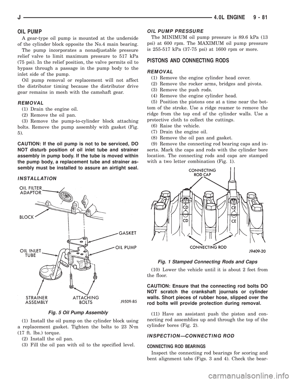
bolts. Remove the pump assembly with gasket (Fig.
5).
CAUTION: If the oil pump is not to be serviced, DO
NOT disturb position of oil inlet tube and strainer
assembly in pump body. If the tube is moved within
the pump body, a replacement tube and strainer as-
sembly must be installed to assure an airtight seal.
INSTALLATION
(1) Install the oil pump on the cylinder block using
a replacement gasket. Tighten the bolts to 23 Nzm
(17 ft. lbs.) torque.
(2) Install the oil pan.
(3) Fill the oil pan with oil to the specified level.
OIL PUMP PRESSURE
The MINIMUM oil pump pressure is 89.6 kPa (13
psi) at 600 rpm. The MAXIMUM oil pump pressure
is 255-517 kPa (37-75 psi) at 1600 rpm or more.
PISTONS AND CONNECTING RODS
REMOVAL
(1) Remove the engine cylinder head cover.
(2) Remove the rocker arms, bridges and pivots.
(3) Remove the push rods.
(4) Remove the engine cylinder head.
(5) Position the pistons one at a time near the bot-
tom of the stroke. Use a ridge reamer to remove the
ridge from the top end of the cylinder walls. Use a
protective cloth to collect the cuttings.
(6) Raise the vehicle.
(7) Drain the engine oil.
(8) Remove the oil pan and gasket.
(9) Remove the connecting rod bearing caps and in-
serts. Mark the caps and rods with the cylinder bore
location. The connecting rods and caps are stamped
with a two letter combination (Fig. 1).
(10) Lower the vehicle until it is about 2 feet from
the floor.
CAUTION: Ensure that the connecting rod bolts DO
NOT scratch the crankshaft journals or cylinder
walls. Short pieces of rubber hose, slipped over the
rod bolts will provide protection during removal.
(11) Have an assistant push the piston and con-
necting rod assemblies up and through the top of the
cylinder bores (Fig. 2).
INSPECTIONÐCONNECTING ROD
CONNECTING ROD BEARINGS
Inspect the connecting rod bearings for scoring and
bent alignment tabs (Figs. 3 and 4). Check the bear-
Fig. 5 Oil Pump Assembly
Fig. 1 Stamped Connecting Rods and Caps
J4.0L ENGINE 9 - 81
Page 1368 of 2158
If the clearance exceeds specification using a pair
of 0.051 mm (0.002 inch) undersize bearing inserts,
measure crankshaft journal diameter with a mi-
crometer. If the journal diameter is correct, the
crankshaft bore in the cylinder block may be mis-
aligned, which requires cylinder block replacement or
machining to true bore.
Replace the crankshaft or grind to accept the ap-
propriate undersize bearing inserts if:
²Journal diameters 1 through 6 are less than
63.4517 mm (2.4981 inches)
²Journal 7 diameter is less than 63.4365 mm
(2.4975 inches).
Once the proper clearances have been obtained,
proceed to Crankshaft Main BearingÐInstallation.
MAIN BEARING JOURNAL DIAMETER (CRANKSHAFT
REMOVED)
Remove the crankshaft from the cylinder block (re-
fer to Cylinder Block - Disassemble).
Clean the oil off the main bearing journal.
Determine the maximum diameter of the journal
with a micrometer. Measure at two locations 90É
apart at each end of the journal.
The maximum allowable taper and out of round is
0.013 mm (0.0005 inch). Compare the measured di-
ameter with the journal diameter specification (Main
Bearing Fitting Chart). Select inserts required to ob-
tain the specified bearing-to-journal clearance.
Install the crankshaft into the cylinder block (refer
to Cylinder Block - Assemble and Crankshaft Main
Bearings - Installation).
INSTALLATION
(1) Lubricate the bearing surface of each insert
with engine oil.
(2) Loosen all the main bearing caps. Install the
main bearing upper inserts.
(3) Install the lower bearing inserts into the main
bearing caps.
(4) Install the main bearing cap(s) and lower in-
sert(s).
(5) Tighten the bolts of caps 1, 2, 4, 5, 6, and 7 to
54 Nzm (40 ft. lbs.) torque. Now tighten these bolts to
95 Nzm (70 ft. lbs.) torque. Finally, tighten these
bolts to 108 Nzm (80 ft. lbs.) torque.
(6) Push the crankshaft forward and backward.
Load the crankshaft front or rear and tighten cap
bolt No.3 to 54 Nzm (40 ft. lbs.) torque. Then tighten
to 95 Nzm (70 ft. lbs.) torque and finally tighten to
108 Nzm (80 ft. lbs.) torque.
(7) Rotate the crankshaft after tightening each
main bearing cap to ensure the crankshaft rotates
freely.
(8) Check crankshaft end play. Crankshaft end
play is controlled by the thrust bearing which is
flange and installed at the No.2 main bearing posi-
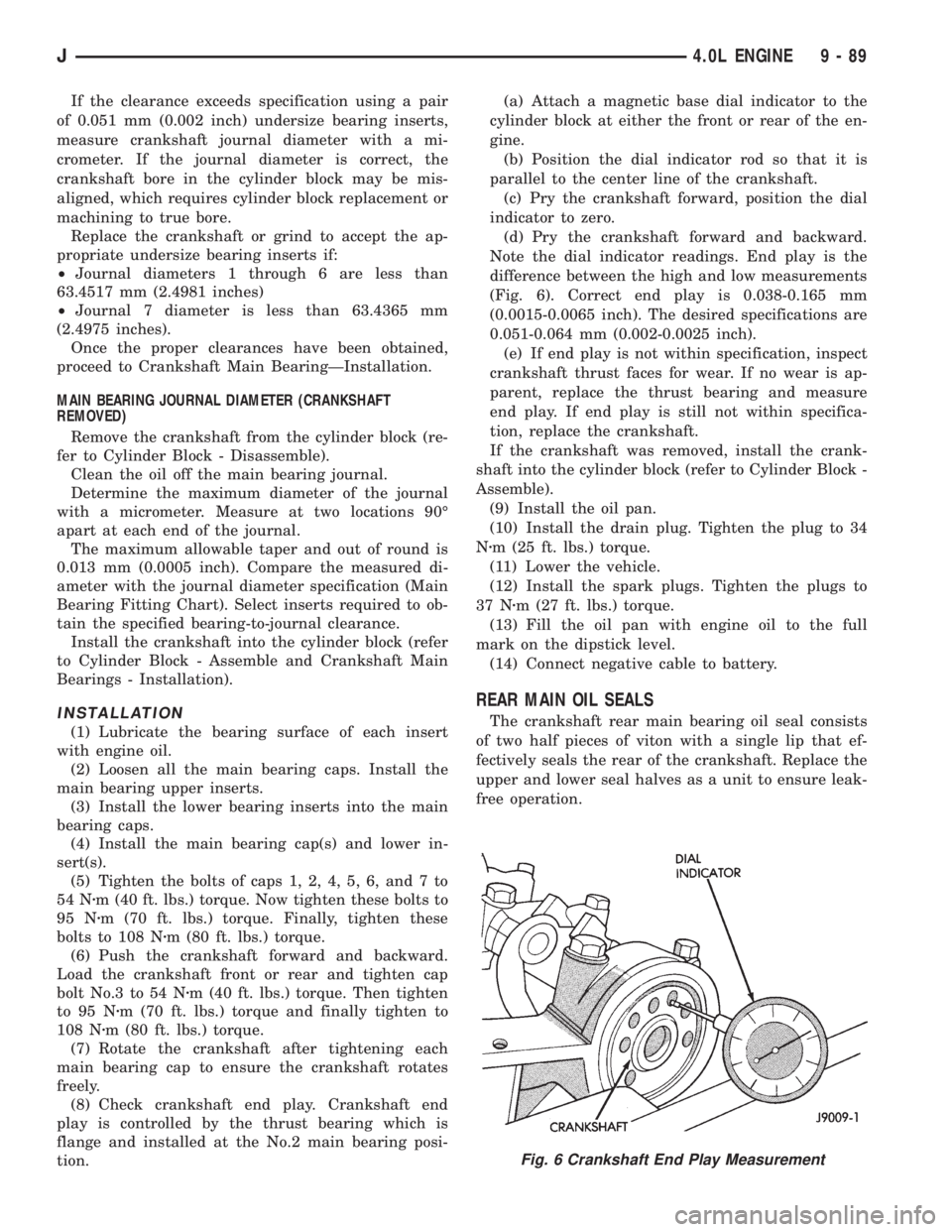
tion.(a) Attach a magnetic base dial indicator to the
cylinder block at either the front or rear of the en-
gine.
(b) Position the dial indicator rod so that it is
parallel to the center line of the crankshaft.
(c) Pry the crankshaft forward, position the dial
indicator to zero.
(d) Pry the crankshaft forward and backward.
Note the dial indicator readings. End play is the
difference between the high and low measurements
(Fig. 6). Correct end play is 0.038-0.165 mm
(0.0015-0.0065 inch). The desired specifications are
0.051-0.064 mm (0.002-0.0025 inch).
(e) If end play is not within specification, inspect
crankshaft thrust faces for wear. If no wear is ap-
parent, replace the thrust bearing and measure
end play. If end play is still not within specifica-
tion, replace the crankshaft.
If the crankshaft was removed, install the crank-
shaft into the cylinder block (refer to Cylinder Block -
Assemble).
(9) Install the oil pan.
(10) Install the drain plug. Tighten the plug to 34
Nzm (25 ft. lbs.) torque.
(11) Lower the vehicle.
(12) Install the spark plugs. Tighten the plugs to
37 Nzm (27 ft. lbs.) torque.
(13) Fill the oil pan with engine oil to the full
mark on the dipstick level.
(14) Connect negative cable to battery.
REAR MAIN OIL SEALS
The crankshaft rear main bearing oil seal consists
of two half pieces of viton with a single lip that ef-
fectively seals the rear of the crankshaft. Replace the
upper and lower seal halves as a unit to ensure leak-
free operation.
Fig. 6 Crankshaft End Play Measurement
J4.0L ENGINE 9 - 89
Page 1371 of 2158
²The front and rear oil galley holes.
²The feed holes for the crankshaft main bearings.
Once the block has been completely cleaned, apply
Loctite PST pipe sealant with Teflon 592 to the
threads of the front and rear oil galley plugs. Tighten
the plugs to 41 Nzm (30 ft. lbs.) torque.
INSPECTIONÐCYLINDER BORE
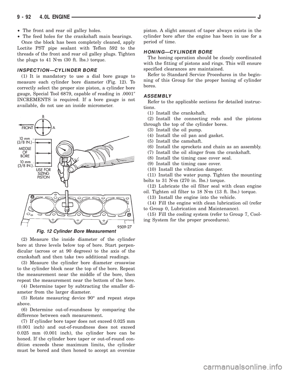
(1) It is mandatory to use a dial bore gauge to
measure each cylinder bore diameter (Fig. 12). To
correctly select the proper size piston, a cylinder bore
gauge, Special Tool 6879, capable of reading in .00019
INCREMENTS is required. If a bore gauge is not
available, do not use an inside micrometer.
(2) Measure the inside diameter of the cylinder
bore at three levels below top of bore. Start perpen-
dicular (across or at 90 degrees) to the axis of the
crankshaft and then take two additional readings.
(3) Measure the cylinder bore diameter crosswise
to the cylinder block near the top of the bore. Repeat
the measurement near the middle of the bore, then
repeat the measurement near the bottom of the bore.
(4) Determine taper by subtracting the smaller di-
ameter from the larger diameter.
(5) Rotate measuring device 90É and repeat steps
above.
(6) Determine out-of-roundness by comparing the
difference between each measurement.
(7) If cylinder bore taper does not exceed 0.025 mm
(0.001 inch) and out-of-roundness does not exceed
0.025 mm (0.001 inch), the cylinder bore can be
honed. If the cylinder bore taper or out-of-round con-
dition exceeds these maximum limits, the cylinder
must be bored and then honed to accept an oversizepiston. A slight amount of taper always exists in the
cylinder bore after the engine has been in use for a
period of time.
HONINGÐCYLINDER BORE
The honing operation should be closely coordinated
with the fitting of pistons and rings. This will ensure
specified clearances are maintained.
Refer to Standard Service Procedures in the begin-
ning of this Group for the proper honing of cylinder
bores.
ASSEMBLY
Refer to the applicable sections for detailed instruc-
tions.
(1) Install the crankshaft.
(2) Install the connecting rods and the pistons
through the top of the cylinder bores.
(3) Install the oil pump.
(4) Install the oil pan and gasket.
(5) Install the camshaft.
(6) Install the sprockets and chain as an assembly.
(7) Install the oil slinger from the crankshaft.
(8) Install the timing case cover seal.
(9) Install the timing case cover.
(10) Install the vibration damper.
(11) Install the water pump. Tighten the mounting
bolts to 31 Nzm (270 in. lbs.) torque.
(12) Lubricate the oil filter seal with clean engine
oil. Tighten oil filter to 18 Nzm (13 ft. lbs.) torque.
(13) Install the engine into the vehicle.
(14) Fill the engine with clean lubrication oil (refer
to Group 0, Lubrication and Maintenance).
(15) Fill the cooling system (refer to Group 7, Cool-
ing System for the proper procedures).
Fig. 12 Cylinder Bore Measurement
9 - 92 4.0L ENGINEJ
Page 1423 of 2158
²Signal ground
Powertrain Control Module (PCM) Outputs:
²A/C clutch relay
²Idle air control (IAC) motor
²Auto shutdown (ASD) relay
²Generator field
²Malfunction indicator lamp (Check Engine Lamp)
²Fuel injectors
²Fuel pump relay
²Ignition coil
²SCI transmit (DRB scan tool connection)
²Shift indicator lamp (manual transmission only)
²Speed control vacuum solenoid
²Speed control vent solenoid
²Tachometer (on instrument panel, if equipped)
²Torque converter clutch relay (3-speed auto. trans.
only)
The PCM contains a voltage convertor. This con-
verts battery voltage to a regulated 8.0 volts. It is
used to power the crankshaft position sensor, cam-
shaft position sensor and vehicle speed sensor. The
PCM also provides a five (5) volt supply for the Man-
ifold Absolute Pressure (MAP) sensor and Throttle
Position Sensor (TPS).
AIR CONDITIONING (A/C) CONTROLSÐPCM INPUT
The A/C control system information applies to fac-
tory installed air conditioning units only.
A/C SELECT SIGNAL:When the A/C switch is in
the ON position and the A/C low-pressure switch is
closed, an input signal is sent to the powertrain con-
trol module (PCM). The signal informs the PCM that
the A/C has been selected. The PCM adjusts idle
speed to a pre-programmed rpm through the idle air
control (IAC) motor to compensate for increased en-
gine load.
A/C REQUEST SIGNAL:Once A/C has been se-
lected, the PCM receives the A/C request signal from
the evaporator switch. The input indicates that the
evaporator temperature is in the proper range for
A/C application. The PCM uses this input to cycle the
A/C compressor clutch (through the A/C relay). It will
also determine the correct engine idle speed through
the IAC motor position.
If the A/C low-pressure switch opens (indicating a
low refrigerant level), the PCM will not receive an
A/C select signal. The PCM will then remove the
ground from the A/C relay. This will deactivate the
A/C compressor clutch.
If the evaporator switch opens, (indicating that
evaporator is not in proper temperature range), the
PCM will not receive the A/C request signal. The
PCM will then remove the ground from the A/C relay,
deactivating the A/C compressor clutch.
AUTOMATIC SHUTDOWN (ASD) SENSEÐPCM
INPUT
A 12 volt signal at this input indicates to the PCM
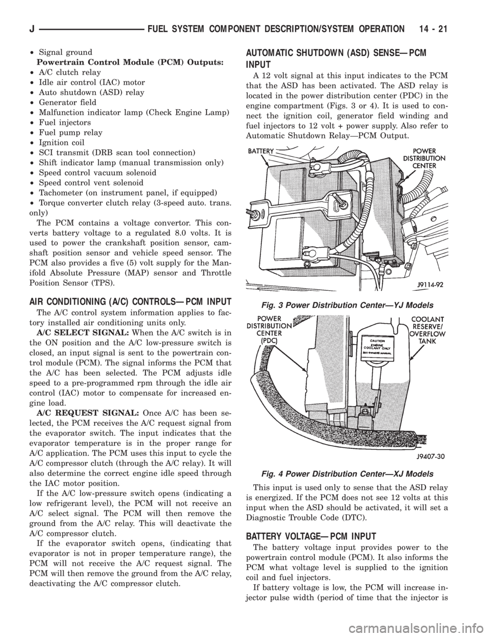
that the ASD has been activated. The ASD relay is
located in the power distribution center (PDC) in the
engine compartment (Figs. 3 or 4). It is used to con-
nect the ignition coil, generator field winding and
fuel injectors to 12 volt + power supply. Also refer to
Automatic Shutdown RelayÐPCM Output.
This input is used only to sense that the ASD relay
is energized. If the PCM does not see 12 volts at this
input when the ASD should be activated, it will set a
Diagnostic Trouble Code (DTC).
BATTERY VOLTAGEÐPCM INPUT
The battery voltage input provides power to the
powertrain control module (PCM). It also informs the
PCM what voltage level is supplied to the ignition
coil and fuel injectors.
If battery voltage is low, the PCM will increase in-
jector pulse width (period of time that the injector is
Fig. 3 Power Distribution CenterÐYJ Models
Fig. 4 Power Distribution CenterÐXJ Models
JFUEL SYSTEM COMPONENT DESCRIPTION/SYSTEM OPERATION 14 - 21
Page 1564 of 2158
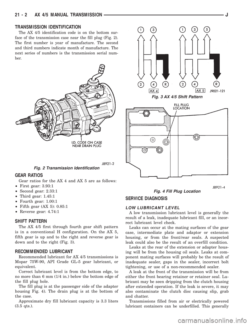
TRANSMISSION IDENTIFICATION
The AX 4/5 identification code is on the bottom sur-
face of the transmission case near the fill plug (Fig. 2).
The first number is year of manufacture. The second
and third numbers indicate month of manufacture. The
next series of numbers is the transmission serial num-
ber.
GEAR RATIOS
Gear ratios for the AX 4 and AX 5 are as follows:
²First gear: 3.93:1
²Second gear: 2.33:1
²Third gear: 1.45:1
²Fourth gear: 1.00:1
²Fifth gear (AX 5): 0.85:1
²Reverse gear: 4.74:1
SHIFT PATTERN
The AX 4/5 first through fourth gear shift pattern
is in a conventional H configuration. On the AX 5,
fifth gear is up and to the right and reverse gear is
down and to the right (Fig. 3).
RECOMMENDED LUBRICANT
Recommended lubricant for AX 4/5 transmissions is
Mopar 75W-90, API Grade GL-5 gear lubricant, or
equivalent.
Correct lubricant level is from the bottom edge, to
no more than 6 mm (1/4 in.) below the bottom edge of
the fill plug hole.
The fill plug is at the passenger side of the adapter
housing Fig. 4). The drain plug is at the bottom of
the case.
Approximate dry fill lubricant capacity is 3.3 liters
(3.5 qts.).
SERVICE DIAGNOSIS
LOW LUBRICANT LEVEL
A low transmission lubricant level is generally the
result of a leak, inadequate lubricant fill, or an incor-
rect lubricant level check.
Leaks can occur at the mating surfaces of the gear
case, intermediate plate and adaptor or extension
housing, or from the front/rear seals. A suspected
leak could also be the result of an overfill condition.
Leaks at the rear of the extension or adapter hous-
ing will be from the housing oil seals. Leaks at com-
ponent mating surfaces will probably be the result of
inadequate sealer, gaps in the sealer, incorrect bolt
tightening, or use of a non-recommended sealer.
A leak at the front of the transmission will be from
either the front bearing retainer or retainer seal. Lu-
bricant may be seen dripping from the clutch housing
after extended operation. If the leak is severe, it may
also contaminate the clutch disc causing slip, grab
and chatter.
Transmissions filled from air or electrically powered
lubricant containers can be underfilled. This generally
Fig. 2 Transmission Identification
Fig. 3 AX 4/5 Shift Pattern
Fig. 4 Fill Plug Location
21 - 2 AX 4/5 MANUAL TRANSMISSIONJ
Page 1565 of 2158

happens when the container delivery mechanism is im-
properly calibrated. Always check the lubricant level af-
ter filling to avoid an under fill condition.
A correct lubricant level check can only be made
when the vehicle is level; use a drive-on hoist to en-
sure this. Also allow the lubricant to settle for a
minute or so before checking. These recommenda-
tions will ensure an accurate check and avoid an un-
der-or-overfill condition.
HARD SHIFTING
Hard shifting is usually caused by a low lubricant
level, improper or contaminated lubricants, compo-
nent damage, incorrect clutch adjustment, or by a
damaged clutch pressure plate or disc.
Substantial lubricant leaks can result in gear, shift
rail, synchro and bearing damage. If a leak goes un-
detected for an extended period, the first indications
of a problem are usually hard shifting and noise.
Incorrect or contaminated lubricants can also con-
tribute to hard shifting. The consequence of using
non-recommended lubricants is noise, excessive wear,
internal bind and hard shifting.
Improper clutch release is a frequent cause of hard
shifting. Incorrect adjustment or a worn, damaged
pressure plate or disc can cause incorrect release. If
the clutch problem is advanced, gear clash during
shifts can result.
Worn or damaged synchro rings can cause gear clash
when shifting into any forward gear. In some new or re-
built transmissions, new synchro rings may tend to
stick slightly causing hard or noisy shifts. In most
cases, this condition will decline as the rings wear-in.
TRANSMISSION NOISE
Most manual transmissions make some noise dur-
ing normal operation. Rotating gears generate a mild
whine that is audible but only at extreme speeds.
Severe, highly audible transmission noise is gener-
ally the result of a lubricant problem. Insufficient,
improper, or contaminated lubricant will promote
rapid wear of gears, synchros, shift rails, forks and
bearings. The overheating caused by a lubricant
problem, can also lead to gear breakage.
TRANSMISSION REMOVAL
(1) Shift transmission into first or third gear. Then
raise vehicle on hoist.
(2) Support engine with adjustable jack stand. Po-
sition wood block between jack and oil pan to avoid
damaging pan.
(3) Disconnect necessary exhaust system components.
(4) Remove skid plate.
(5) Disconnect rear cushion and bracket from
transmission (Fig. 5).
(6) Remove rear crossmember.
Fig. 5 Rear Mount Components (YJ Shown)
JAX 4/5 MANUAL TRANSMISSION 21 - 3
Page 1596 of 2158
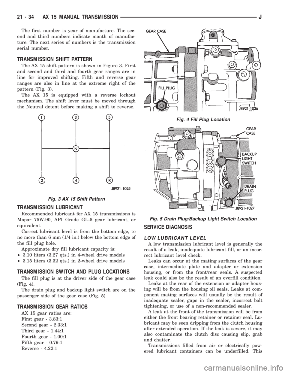
The first number is year of manufacture. The sec-
ond and third numbers indicate month of manufac-
ture. The next series of numbers is the transmission
serial number.
TRANSMISSION SHIFT PATTERN
The AX 15 shift pattern is shown in Figure 3. First
and second and third and fourth gear ranges are in
line for improved shifting. Fifth and reverse gear
ranges are also in line at the extreme right of the
pattern (Fig. 3).
The AX 15 is equipped with a reverse lockout
mechanism. The shift lever must be moved through
the Neutral detent before making a shift to reverse.
TRANSMISSION LUBRICANT
Recommended lubricant for AX 15 transmissions is
Mopar 75W-90, API Grade GL-5 gear lubricant, or
equivalent.
Correct lubricant level is from the bottom edge, to
no more than 6 mm (1/4 in.) below the bottom edge of
the fill plug hole.
Approximate dry fill lubricant capacity is:
²3.10 liters (3.27 qts.) in 4-wheel drive models
²3.15 liters (3.32 qts.) in 2-wheel drive models
TRANSMISSION SWITCH AND PLUG LOCATIONS
The fill plug is at the driver side of the gear case
(Fig. 4).
The drain plug and backup light switch are on the
passenger side of the gear case (Fig. 5).
TRANSMISSION GEAR RATIOS
AX 15 gear ratios are:
First gear - 3.83:1
Second gear - 2.33:1
Third gear - 1.44:1
Fourth gear - 1.00:1
Fifth gear - 0.79:1
Reverse - 4.22:1
SERVICE DIAGNOSIS
LOW LUBRICANT LEVEL
A low transmission lubricant level is generally the
result of a leak, inadequate lubricant fill, or an incor-
rect lubricant level check.
Leaks can occur at the mating surfaces of the gear
case, intermediate plate and adapter or extension
housing, or from the front/rear seals. A suspected
leak could also be the result of an overfill condition.
Leaks at the rear of the extension or adapter hous-
ing will be from the housing oil seals. Leaks at com-
ponent mating surfaces will usually be the result of
inadequate sealer, gaps in the sealer, incorrect bolt
tightening, or use of a non-recommended sealer.
A leak at the front of the transmission will be from
either the front bearing retainer or retainer seal. Lu-
bricant may be seen dripping from the clutch housing
after extended operation. If the leak is severe, it may
also contaminate the clutch disc causing slip, grab
and chatter.
Transmissions filled from air or electrically pow-
ered lubricant containers can be underfilled. This
Fig. 3 AX 15 Shift Pattern
Fig. 4 Fill Plug Location
Fig. 5 Drain Plug/Backup Light Switch Location
21 - 34 AX 15 MANUAL TRANSMISSIONJ
Page 1632 of 2158
30RH/32RH TRANSMISSION DIAGNOSIS
INDEX
page page
Air Pressure Test......................... 74
Analyzing the Road Test.................... 71
Converter Housing Leak Diagnosis............ 75
Converter Stall Test........................ 74
Diagnosis Guides and Charts................ 77
Effects of Incorrect Fluid Level............... 71
Fluid Level Check......................... 70Gearshift Cable/Linkage Adjustment........... 71
General Information....................... 70
Hydraulic Pressure Test.................... 72
Preliminary Diagnosis...................... 70
Road Test............................... 71
Transmission Throttle Valve Cable Adjustment.... 71
GENERAL INFORMATION
Automatic transmission problems are generally a
result of:
²poor engine performance
²incorrect fluid level
²incorrect throttle valve cable adjustment
²incorrect band adjustment
²incorrect hydraulic control pressure adjustments
²hydraulic component malfunctions
²mechanical component malfunctions.
Begin diagnosis by checking the easily accessible
items such as fluid level, fluid condition and control
linkage adjustment. A road test will determine if fur-
ther diagnosis is necessary.
Procedures outlined in this section should be per-
formed in the following sequence to realize the most
accurate results:
²Preliminary diagnosis
²Check fluid level and condition
²Check control linkage Adjustment
²Road test
²Stall test
²Hydraulic pressure test
²Air pressure tests
²Leak test
²Analyze test results and consult diagnosis charts
PRELIMINARY DIAGNOSIS
Two basic procedures are required. One procedure
for vehicles that are driveable and an alternate pro-
cedure for disabled vehicles (will not back up or move
forward).
Vehicle Is Driveable
(1) Check fluid level and condition.
(2) Adjust throttle cable and gearshift linkage if
complaint was based on delayed, erratic, or harsh
shifts.
(3) Road test vehicle and note transmission operat-
ing characteristics.(4) Perform stall test if complaint is based on slug-
gish, low speed acceleration or abnormal throttle
opening needed to maintain normal speeds with
properly tuned engine.
(5) Perform hydraulic pressure tests.
(6) Perform air pressure test to check clutch-band
operation.
Vehicle Is Disabled
(1) Check fluid level and condition.
(2) Check for broken, disconnected throttle linkage.
(3) Check for cracked, leaking cooler lines, or loose,
missing pressure port plugs.
(4) Raise vehicle, start engine, shift transmission
into gear and note following:
(a) If propeller shafts turn but wheels do not,
problem is with differential or axle shafts.
(b) If propeller shafts do not turn and transmis-
sion is noisy, stop engine. Remove oil pan, and
check for debris. If pan is clear, remove transmis-
sion and check for damaged drive plate, converter,
oil pump or input shaft.
(c) If propeller shafts do not turn and transmis-
sion is not noisy, perform hydraulic pressure test to
determine if problem is a hydraulic or mechanical.
FLUID LEVEL CHECK
Transmission fluid level should be checked monthly
under normal operation. If the vehicle is used for
trailer towing or similar heavy load hauling, check
fluid level and condition weekly.
Fluid level is checked with the engine running at
curb idle speed, the transmission in Neutral and the
transmission fluid at normal operating temperature.
FLUID LEVEL CHECK PROCEDURE
(1) Transmission fluid must be at normal operating
temperature for accurate fluid level check. Drive ve-
hicle if necessary to bring fluid temperature up to
normal hot operating temperature of 82ÉC (180ÉF).
(2) Position vehicle on level surface. This is ex-
tremely important for accurate fluid level check.
(3) Start and run engine at curb idle speed.
21 - 70 30RH/32RH TRANSMISSION DIAGNOSISJ