1995 JEEP YJ manual transmission
[x] Cancel search: manual transmissionPage 1433 of 2158
²The powertrain control module (PCM) pre-posi-
tions the idle air control (IAC) motor.
²The PCM determines atmospheric air pressure
from the MAP sensor input to determine basic fuel
strategy.
²The PCM monitors the engine coolant temperature
sensor input. The PCM modifies fuel strategy based
on this input.
²Intake manifold air temperature sensor input is
monitored
²Throttle position sensor (TPS) is monitored
²The auto shutdown (ASD) relay is energized by the
PCM for approximately three seconds.
²The fuel pump is energized through the fuel pump
relay by the PCM. The fuel pump will operate for ap-
proximately three seconds unless the engine is oper-
ating or the starter motor is engaged
²The O2S sensor heater element is energized
through the fuel pump relay. The O2S sensor input is
not used by the PCM to calibrate air-fuel ratio dur-
ing this mode of operation.
²The up-shift indicator lamp is illuminated (manual
transmission only).
ENGINE START-UP MODE
This is an Open Loop mode. The following actions
occur when the starter motor is engaged.
The powertrain control module (PCM) receives in-
puts from:
²Battery voltage
²Engine coolant temperature sensor
²Crankshaft position sensor
²Intake manifold air temperature sensor
²Manifold absolute pressure (MAP) sensor
²Throttle position sensor (TPS)
²Starter motor relay
²Camshaft position sensor signal
The PCM monitors the crankshaft position sensor.
If the PCM does not receive a crankshaft position
sensor signal within 3 seconds of cranking the en-
gine, it will shut down the fuel injection system.
The fuel pump is activated by the PCM through
the fuel pump relay.
Voltage is applied to the fuel injectors with the
PCM. The PCM will then control the injection se-
quence and injector pulse width by turning the
ground circuit to each individual injector on and off.
The PCM determines the proper ignition timing ac-
cording to input received from the crankshaft posi-
tion sensor.
ENGINE WARM-UP MODE
This is an Open Loop mode. During engine warm-
up, the powertrain control module (PCM) receives in-
puts from:
²Battery voltage
²Crankshaft position sensor
²Engine coolant temperature sensor²Intake manifold air temperature sensor
²Manifold absolute pressure (MAP) sensor
²Throttle position sensor (TPS)
²Camshaft position sensor signal (in the distribu-
tor)
²Park/neutral switch (gear indicator signalÐauto.
trans. only)
²Air conditioning select signal (if equipped)
²Air conditioning request signal (if equipped)
Based on these inputs the following occurs:
²Voltage is applied to the fuel injectors with the
powertrain control module (PCM). The PCM will
then control the injection sequence and injector pulse
width by turning the ground circuit to each individ-
ual injector on and off.
²The PCM adjusts engine idle speed through the
idle air control (IAC) motor and adjusts ignition tim-
ing.
²The PCM operates the A/C compressor clutch
through the clutch relay. This is done if A/C has been
selected by the vehicle operator and requested by the
A/C thermostat.
²If the vehicle has a manual transmission, the up-
shift lamp is operated by the PCM.
²When engine has reached operating temperature,
the PCM will begin monitoring O2S sensor input.
The system will then leave the warm-up mode and go
into closed loop operation.
IDLE MODE
When the engine is at operating temperature, this
is a Closed Loop mode. At idle speed, the powertrain
control module (PCM) receives inputs from:
²Air conditioning select signal (if equipped)
²Air conditioning request signal (if equipped)
²Battery voltage
²Crankshaft position sensor
²Engine coolant temperature sensor
²Intake manifold air temperature sensor
²Manifold absolute pressure (MAP) sensor
²Throttle position sensor (TPS)
²Camshaft position sensor signal (in the distribu-
tor)
²Battery voltage
²Park/neutral switch (gear indicator signalÐauto.
trans. only)
²Oxygen sensor
Based on these inputs, the following occurs:
²Voltage is applied to the fuel injectors with the
powertrain control module (PCM). The PCM will
then control injection sequence and injector pulse
width by turning the ground circuit to each individ-
ual injector on and off.
²The PCM monitors the O2S sensor input and ad-
justs air-fuel ratio by varying injector pulse width. It
also adjusts engine idle speed through the idle air
control (IAC) motor.
JFUEL SYSTEM COMPONENT DESCRIPTION/SYSTEM OPERATION 14 - 31
Page 1435 of 2158
²The PCM opens the ground circuit to the A/C
clutch relay to disengage the A/C compressor clutch.
This will be done for approximately 15 seconds (if the
air conditioning system is operating).
If the vehicle has a manual transmission, the up-
shift lamp is operated by the PCM.
IGNITION SWITCH OFF MODE
When ignition switch is turned to OFF position,
the PCM stops operating the injectors, ignition coil,
ASD relay and fuel pump relay.
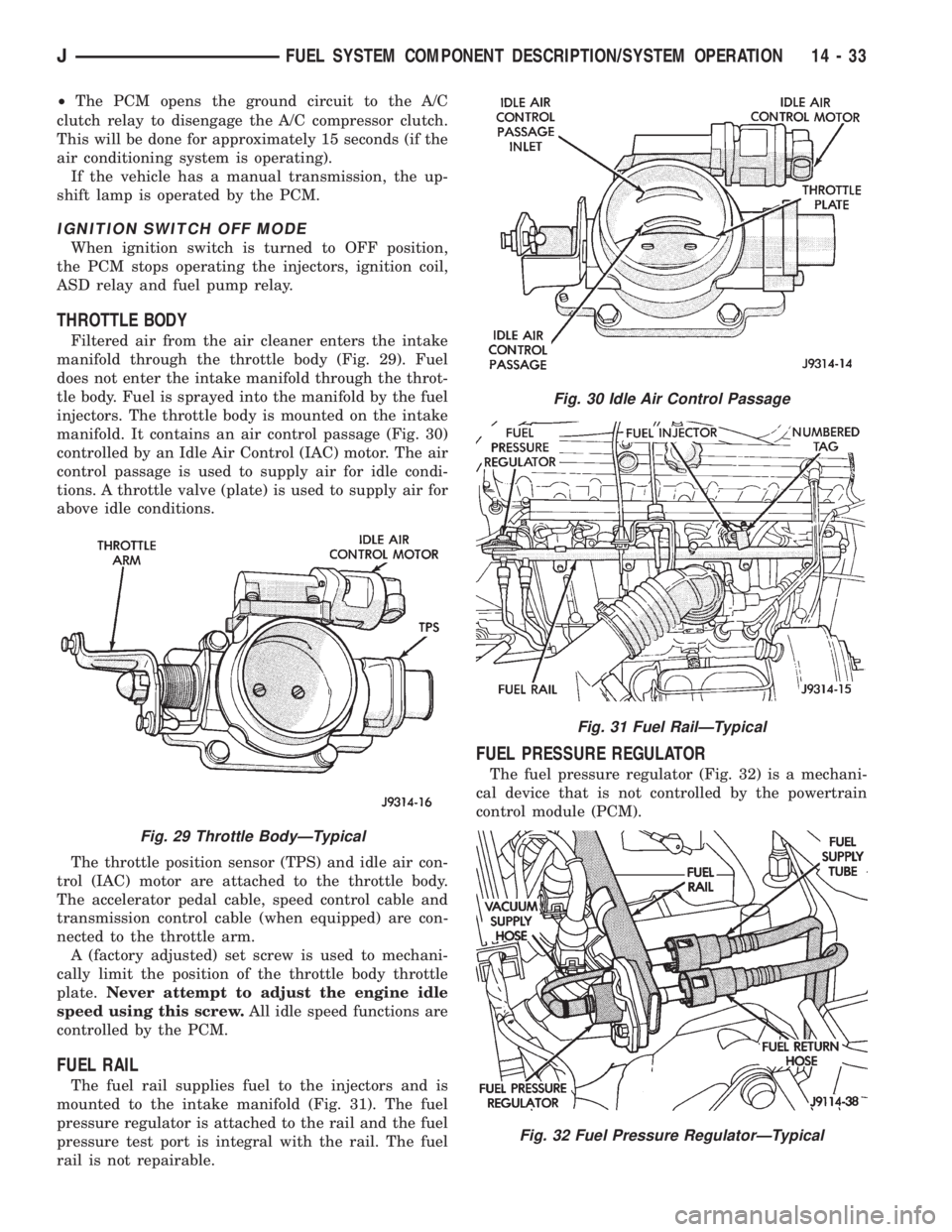
THROTTLE BODY
Filtered air from the air cleaner enters the intake
manifold through the throttle body (Fig. 29). Fuel
does not enter the intake manifold through the throt-
tle body. Fuel is sprayed into the manifold by the fuel
injectors. The throttle body is mounted on the intake
manifold. It contains an air control passage (Fig. 30)
controlled by an Idle Air Control (IAC) motor. The air
control passage is used to supply air for idle condi-
tions. A throttle valve (plate) is used to supply air for
above idle conditions.
The throttle position sensor (TPS) and idle air con-
trol (IAC) motor are attached to the throttle body.
The accelerator pedal cable, speed control cable and
transmission control cable (when equipped) are con-
nected to the throttle arm.
A (factory adjusted) set screw is used to mechani-
cally limit the position of the throttle body throttle
plate.Never attempt to adjust the engine idle
speed using this screw.All idle speed functions are
controlled by the PCM.
FUEL RAIL
The fuel rail supplies fuel to the injectors and is
mounted to the intake manifold (Fig. 31). The fuel
pressure regulator is attached to the rail and the fuel
pressure test port is integral with the rail. The fuel
rail is not repairable.
FUEL PRESSURE REGULATOR
The fuel pressure regulator (Fig. 32) is a mechani-
cal device that is not controlled by the powertrain
control module (PCM).
Fig. 29 Throttle BodyÐTypical
Fig. 30 Idle Air Control Passage
Fig. 31 Fuel RailÐTypical
Fig. 32 Fuel Pressure RegulatorÐTypical
JFUEL SYSTEM COMPONENT DESCRIPTION/SYSTEM OPERATION 14 - 33
Page 1442 of 2158
plugged catalytic convertor.
(27) If equipped with automatic transmission, ver-
ify that electrical harness is firmly connected to park/
neutral safety switch. Refer to Automatic
Transmission section of Group 21.
(28) Verify that the harness connector is firmly
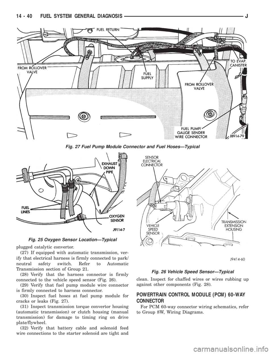
connected to the vehicle speed sensor (Fig. 26).
(29) Verify that fuel pump module wire connector
is firmly connected to harness connector.
(30) Inspect fuel hoses at fuel pump module for
cracks or leaks (Fig. 27).
(31) Inspect transmission torque convertor housing
(automatic transmission) or clutch housing (manual
transmission) for damage to timing ring on drive
plate/flywheel.
(32) Verify that battery cable and solenoid feed
wire connections to the starter solenoid are tight andclean. Inspect for chaffed wires or wires rubbing up
against other components (Fig. 28).
POWERTRAIN CONTROL MODULE (PCM) 60-WAY
CONNECTOR
For PCM 60-way connector wiring schematics, refer
to Group 8W, Wiring Diagrams.
Fig. 27 Fuel Pump Module Connector and Fuel HosesÐTypical
Fig. 25 Oxygen Sensor LocationÐTypical
Fig. 26 Vehicle Speed SensorÐTypical
14 - 40 FUEL SYSTEM GENERAL DIAGNOSISJ
Page 1467 of 2158
INSTALLATION
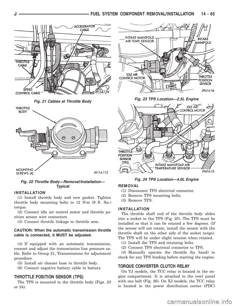
(1) Install throttle body and new gasket. Tighten
throttle body mounting bolts to 12 Nzm (9 ft. lbs.)
torque.
(2) Connect idle air control motor and throttle po-
sition sensor wire connectors.
(3) Connect throttle linkage to throttle arm.
CAUTION: When the automatic transmission throttle
cable is connected, it MUST be adjusted.
(4) If equipped with an automatic transmission,
connect and adjust the transmission line pressure ca-
ble. Refer to Group 21, Transmissions for adjustment
procedure.
(5) Install air cleaner hose to throttle body.
(6) Connect negative battery cable to battery.
THROTTLE POSITION SENSOR (TPS)
The TPS is mounted to the throttle body (Figs. 23
or 24).
REMOVAL
(1) Disconnect TPS electrical connector.
(2) Remove TPS mounting bolts.
(3) Remove TPS.
INSTALLATION
The throttle shaft end of the throttle body slides
into a socket in the TPS (Fig. 25). The TPS must be
installed so that it can be rotated a few degrees. (If
the sensor will not rotate, install the sensor with the
throttle shaft on the other side of the socket tangs).
The TPS will be under slight tension when rotated.
(1) Install the TPS and retaining bolts.
(2) Connect TPS electrical connector to TPS.
(3) Manually operate the throttle (by hand) to
check for any TPS binding before starting the engine.
TORQUE CONVERTER CLUTCH RELAY
On YJ models, the TCC relay is located in the en-
gine compartment. It is attached to the cowl panel
with one bolt (Fig. 26). On XJ models, the TCC relay
is located in the power distribution center (PDC)
Fig. 21 Cables at Throttle Body
Fig. 22 Throttle BodyÐRemoval/InstallationÐ
Typical
Fig. 23 TPS LocationÐ2.5L Engine
Fig. 24 TPS LocationÐ4.0L Engine
JFUEL SYSTEM COMPONENT REMOVAL/INSTALLATION 14 - 65
Page 1563 of 2158
TRANSMISSION AND TRANSFER CASE
CONTENTS
page page
30RH/32RH AUTOMATIC TRANSMISSION.... 67
AW 4 AUTOMATIC TRANSMISSION........ 165
AX 15 MANUAL TRANSMISSION........... 33
AX 4/5 MANUAL TRANSMISSION............ 1NP231 TRANSFER CASE................. 283
NP242 TRANSFER CASE................. 306
TRANSMISSION/TRANSFER CASE
SPECIFICATIONS..................... 333
AX 4/5 MANUAL TRANSMISSION
INDEX
page page
Cleaning and Inspection.................... 13
Gear Ratios.............................. 2
General Information........................ 1
Recommended Lubricant.................... 2
Service Diagnosis.......................... 2
Shift Pattern.............................. 2Transmission Assembly and Adjustment......... 16
Transmission Disassembly and Overhaul......... 5
Transmission Identification................... 2
Transmission Installation..................... 5
Transmission Removal...................... 3
GENERAL INFORMATION
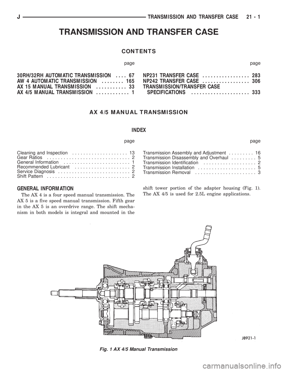
The AX 4 is a four speed manual transmission. The
AX 5 is a five speed manual transmission. Fifth gear
in the AX 5 is an overdrive range. The shift mecha-
nism in both models is integral and mounted in theshift tower portion of the adapter housing (Fig. 1).
The AX 4/5 is used for 2.5L engine applications.
Fig. 1 AX 4/5 Manual Transmission
JTRANSMISSION AND TRANSFER CASE 21 - 1
Page 1564 of 2158
TRANSMISSION IDENTIFICATION
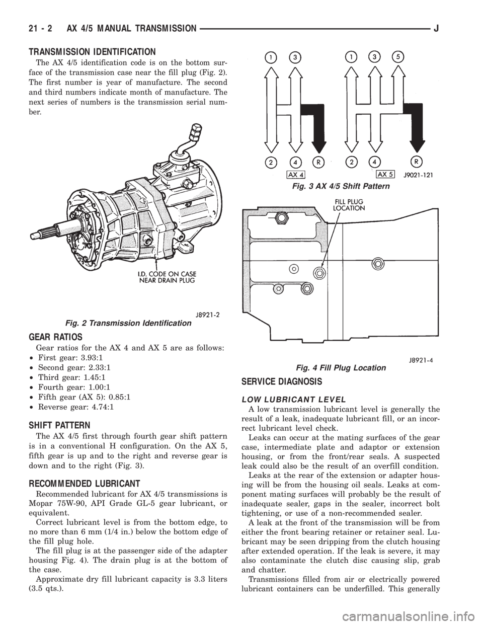
The AX 4/5 identification code is on the bottom sur-
face of the transmission case near the fill plug (Fig. 2).
The first number is year of manufacture. The second
and third numbers indicate month of manufacture. The
next series of numbers is the transmission serial num-
ber.
GEAR RATIOS
Gear ratios for the AX 4 and AX 5 are as follows:
²First gear: 3.93:1
²Second gear: 2.33:1
²Third gear: 1.45:1
²Fourth gear: 1.00:1
²Fifth gear (AX 5): 0.85:1
²Reverse gear: 4.74:1
SHIFT PATTERN
The AX 4/5 first through fourth gear shift pattern
is in a conventional H configuration. On the AX 5,
fifth gear is up and to the right and reverse gear is
down and to the right (Fig. 3).
RECOMMENDED LUBRICANT
Recommended lubricant for AX 4/5 transmissions is
Mopar 75W-90, API Grade GL-5 gear lubricant, or
equivalent.
Correct lubricant level is from the bottom edge, to
no more than 6 mm (1/4 in.) below the bottom edge of
the fill plug hole.
The fill plug is at the passenger side of the adapter
housing Fig. 4). The drain plug is at the bottom of
the case.
Approximate dry fill lubricant capacity is 3.3 liters
(3.5 qts.).
SERVICE DIAGNOSIS
LOW LUBRICANT LEVEL
A low transmission lubricant level is generally the
result of a leak, inadequate lubricant fill, or an incor-
rect lubricant level check.
Leaks can occur at the mating surfaces of the gear
case, intermediate plate and adaptor or extension
housing, or from the front/rear seals. A suspected
leak could also be the result of an overfill condition.
Leaks at the rear of the extension or adapter hous-
ing will be from the housing oil seals. Leaks at com-
ponent mating surfaces will probably be the result of
inadequate sealer, gaps in the sealer, incorrect bolt
tightening, or use of a non-recommended sealer.
A leak at the front of the transmission will be from
either the front bearing retainer or retainer seal. Lu-
bricant may be seen dripping from the clutch housing
after extended operation. If the leak is severe, it may
also contaminate the clutch disc causing slip, grab
and chatter.
Transmissions filled from air or electrically powered
lubricant containers can be underfilled. This generally
Fig. 2 Transmission Identification
Fig. 3 AX 4/5 Shift Pattern
Fig. 4 Fill Plug Location
21 - 2 AX 4/5 MANUAL TRANSMISSIONJ
Page 1565 of 2158

happens when the container delivery mechanism is im-
properly calibrated. Always check the lubricant level af-
ter filling to avoid an under fill condition.
A correct lubricant level check can only be made
when the vehicle is level; use a drive-on hoist to en-
sure this. Also allow the lubricant to settle for a
minute or so before checking. These recommenda-
tions will ensure an accurate check and avoid an un-
der-or-overfill condition.
HARD SHIFTING
Hard shifting is usually caused by a low lubricant
level, improper or contaminated lubricants, compo-
nent damage, incorrect clutch adjustment, or by a
damaged clutch pressure plate or disc.
Substantial lubricant leaks can result in gear, shift
rail, synchro and bearing damage. If a leak goes un-
detected for an extended period, the first indications
of a problem are usually hard shifting and noise.
Incorrect or contaminated lubricants can also con-
tribute to hard shifting. The consequence of using
non-recommended lubricants is noise, excessive wear,
internal bind and hard shifting.
Improper clutch release is a frequent cause of hard
shifting. Incorrect adjustment or a worn, damaged
pressure plate or disc can cause incorrect release. If
the clutch problem is advanced, gear clash during
shifts can result.
Worn or damaged synchro rings can cause gear clash
when shifting into any forward gear. In some new or re-
built transmissions, new synchro rings may tend to
stick slightly causing hard or noisy shifts. In most
cases, this condition will decline as the rings wear-in.
TRANSMISSION NOISE
Most manual transmissions make some noise dur-
ing normal operation. Rotating gears generate a mild
whine that is audible but only at extreme speeds.
Severe, highly audible transmission noise is gener-
ally the result of a lubricant problem. Insufficient,
improper, or contaminated lubricant will promote
rapid wear of gears, synchros, shift rails, forks and
bearings. The overheating caused by a lubricant
problem, can also lead to gear breakage.
TRANSMISSION REMOVAL
(1) Shift transmission into first or third gear. Then
raise vehicle on hoist.
(2) Support engine with adjustable jack stand. Po-
sition wood block between jack and oil pan to avoid
damaging pan.
(3) Disconnect necessary exhaust system components.
(4) Remove skid plate.
(5) Disconnect rear cushion and bracket from
transmission (Fig. 5).
(6) Remove rear crossmember.
Fig. 5 Rear Mount Components (YJ Shown)
JAX 4/5 MANUAL TRANSMISSION 21 - 3
Page 1566 of 2158
(7) Disconnect transfer case shift linkage at trans-
fer case.
(8) Disconnect vehicle speed sensor wires and
transfer case vent hose.
(9) Remove slave cylinder from clutch housing.
(10) Disconnect transmission shift lever as follows:
(a) Lower transmission-transfer case assembly
approximately 7-8 cm (3 in.) for access to shift le-
ver.
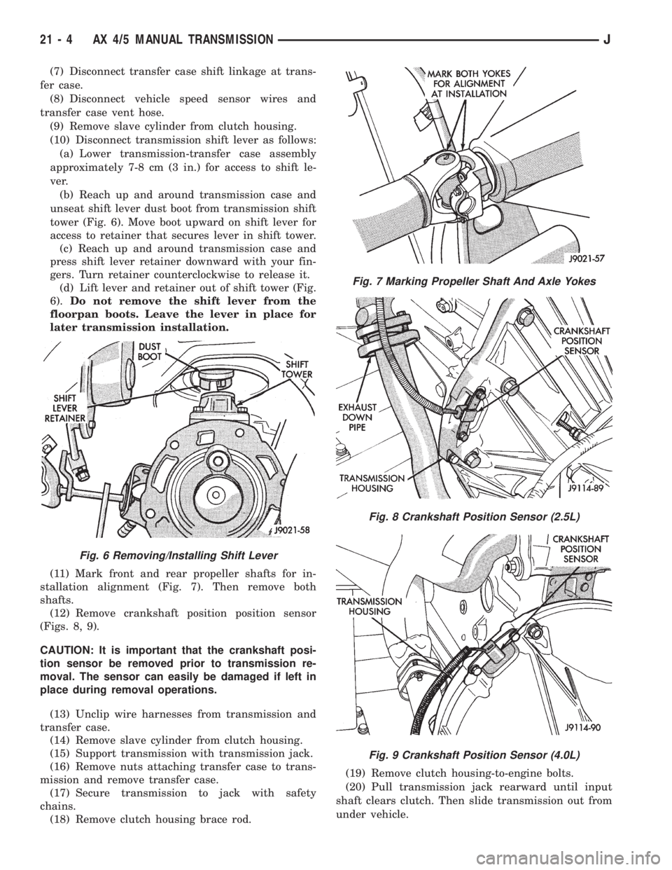
(b) Reach up and around transmission case and
unseat shift lever dust boot from transmission shift
tower (Fig. 6). Move boot upward on shift lever for
access to retainer that secures lever in shift tower.
(c) Reach up and around transmission case and
press shift lever retainer downward with your fin-
gers. Turn retainer counterclockwise to release it.
(d) Lift lever and retainer out of shift tower (Fig.
6).Do not remove the shift lever from the
floorpan boots. Leave the lever in place for
later transmission installation.
(11) Mark front and rear propeller shafts for in-
stallation alignment (Fig. 7). Then remove both
shafts.
(12) Remove crankshaft position position sensor
(Figs. 8, 9).
CAUTION: It is important that the crankshaft posi-
tion sensor be removed prior to transmission re-
moval. The sensor can easily be damaged if left in
place during removal operations.
(13) Unclip wire harnesses from transmission and
transfer case.
(14) Remove slave cylinder from clutch housing.
(15) Support transmission with transmission jack.
(16) Remove nuts attaching transfer case to trans-
mission and remove transfer case.
(17) Secure transmission to jack with safety
chains.
(18) Remove clutch housing brace rod.(19) Remove clutch housing-to-engine bolts.
(20) Pull transmission jack rearward until input
shaft clears clutch. Then slide transmission out from
under vehicle.
Fig. 6 Removing/Installing Shift Lever
Fig. 7 Marking Propeller Shaft And Axle Yokes
Fig. 8 Crankshaft Position Sensor (2.5L)
Fig. 9 Crankshaft Position Sensor (4.0L)
21 - 4 AX 4/5 MANUAL TRANSMISSIONJ