1995 JEEP YJ front brakes
[x] Cancel search: front brakesPage 1661 of 2158
30RH/32RH IN-VEHICLE SERVICE
INDEX
page page
Converter Drainback Check Valve Service...... 113
Fluid and Filter Replacement................. 99
Fluid Level Check......................... 99
Front Band Adjustment.................... 102
Governor and Park Gear Service............. 105
Oil Filter Replacement..................... 103
Park Interlock Cable Adjustment (XJ).......... 101
Park Lock Component Replacement.......... 108
Park/Neutral Position Switch Service.......... 109
Rear Band Adjustment.................... 103
Recommended Fluid....................... 99Refilling After Overhaul or Fluid/Filter Change . . . 100
Shift Cable Adjustment (XJ)................. 100
Shift Linkage Adjustment (YJ)............... 100
Speedometer Service..................... 109
Throttle Valve Cable Adjustment (XJ/YJ)....... 101
Transmission Cooler Flow Testing............ 113
Transmission Cooler Line and Fitting Service.... 111
Transmission Cooler Reverse Flushing......... 114
Valve Body Installation.................... 104
Valve Body Removal...................... 104
Valve Body Service....................... 104
RECOMMENDED FLUID
Recommended (and preferred) fluid for 30RH/32RH
transmissions is Mopar ATF Plus, type 7176.
Dexron II is not really recommended and should
only be used when ATF Plus is not available.
FLUID LEVEL CHECK
Transmission fluid level should be checked monthly
under normal operation. If the vehicle is used for
trailer towing or similar heavy load hauling, check
fluid level and condition weekly.
Fluid level is checked with the engine running at
curb idle speed, the transmission in Neutral and the
transmission fluid at normal operating temperature.
FLUID LEVEL CHECK PROCEDURE
(1) Transmission fluid must be at normal operating
temperature for accurate fluid level check. Drive ve-
hicle if necessary to bring fluid temperature up to
normal hot operating temperature of 82ÉC (180ÉF).
(2) Position vehicle on level surface. This is ex-
tremely important for accurate fluid level check.
(3) Start and run engine at curb idle speed.
(4) Apply parking brakes.
(5) Shift transmission momentarily into all gear
ranges. Then shift transmission back to Neutral.
(6) Clean top of filler tube and dipstick to keep dirt
from entering tube.
(7) Remove dipstick and check fluid level as fol-
lows:
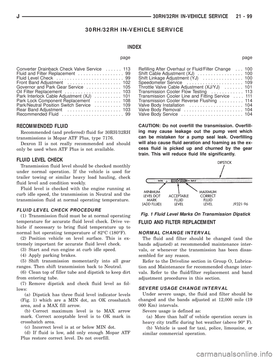
(a) Dipstick has three fluid level indicator levels
(Fig. 1) which are a MIN dot, an OK crosshatch
area, and a MAX fill arrow.
(b) Correct maximum level is to MAX arrow
mark. Correct acceptable level is to OK mark in
crosshatch area.
(c) Incorrect level is at or below MIN dot.
(d) If fluid is low, add only enough Mopar ATF
Plus restore correct level. Do not overfill.CAUTION: Do not overfill the transmission. Overfill-
ing may cause leakage out the pump vent which
can be mistaken for a pump seal leak. Overfilling
will also cause fluid aeration and foaming as the ex-
cess fluid is picked up and churned by the gear
train. This will reduce fluid life significantly.
FLUID AND FILTER REPLACEMENT
NORMAL CHANGE INTERVAL
The fluid and filter should be changed (and the
bands adjusted) at recommended maintenance inter-
vals, or whenever the transmission has been disas-
sembled for any reason.
Refer to the Driveline section in Group O, Lubrica-
tion and Maintenance for recommended change inter-
vals. Refer to the fluid/filter replacement and band
adjustment procedures in this section.
SEVERE USAGE CHANGE INTERVAL
Under severe usage, the fluid and filter should be
changed and the bands adjusted at 12,000 mile (19
000 Km) intervals.
Severe usage is defined as:
(a) More than half of vehicle operation occurs in
heavy city traffic during hot weather (above 90É F).
(b) Vehicle is used for taxi, police, limousine, or
similar commercial operation.
Fig. 1 Fluid Level Marks On Transmission Dipstick
J30RH/32RH IN-VEHICLE SERVICE 21 - 99
Page 1662 of 2158
(c) Vehicle is used for trailer towing or heavy
load hauling.
FLUID/FILTER REPLACEMENT PROCEDURE
(1) Raise vehicle.
(2) Remove oil pan and drain fluid.
(3) Clean oil pan and pan magnet. Then clean re-
maining gasket material from gasket surface of
transmission case.
(4) Remove fluid filter screws and remove filter.
(5) Position new filter on valve body and install fil-
ter screws. Tighten screws to 4 Nzm (35 in. lbs.)
torque.
(6) Adjust rear band at this time if required.
(7) Position new gasket on oil pan and install pan
on transmission. Tighten pan bolts to 150 in. lbs. (17
Nzm) torque.
(8) Adjust front band at this time if required.
(9) Lower vehicle and refill transmission with Mo-
par ATF Plus, type 7176 fluid.
REFILLING AFTER OVERHAUL OR FLUID/FILTER
CHANGE
The most effective way to avoid overfilling after a
fluid change or overhaul is as follows:
(1) Remove dipstick and insert clean funnel in
transmission fill tube.
(2) Add following initial quantity of Mopar ATF
Plus to transmission:
(a) If only fluid and filter were changed, add3
pints (1-1/2 quarts)of ATF Plus to transmission.
(b) If transmission was completely overhauled
and torque converter was replaced or drained, add
10 pints (5 quarts)of ATF Plus to transmission.
(3) Apply parking brakes.
(4) Start and run engine at normal curb idle speed.
(5) Apply service brakes, shift transmission
through all gear ranges then back to Neutral, and
leave engine running at curb idle speed.
(6) Remove funnel, insert dipstick and check fluid
level. Add only enough fluid to bring level toMIN
dot mark on dipstick.
(7) Drive vehicle until transmission fluid is at nor-
mal operating temperature. Then recheck fluid level
as described in next step.
(8) Leave engine running at curb idle speed, shift
into Neutral, and check fluid level again. This time,
add just enough fluid to bring level up toMAX ar-
row mark but do not overfill.
(9) When fluid level is correct, shut engine off, re-
lease park brake, remove funnel, and reseat dipstick
in fill tube.
SHIFT LINKAGE ADJUSTMENT (YJ)
(1) Check linkage adjustment by starting engine in
Park and Neutral.(2) Adjustment is OK if engine starts only in park
and Neutral. Adjustment is incorrect if engine starts
in one but not both positions.
(3) If engine starts in any position other than Park
or Neutral, or if engine will not start at all, park/
neutral position switch may be faulty.
(4) Shift transmission into Park.
(5) Raise vehicle.
(6) Check condition of shift rods, bellcrank,
bellcrank brackets and linkage bushings/grommets
(Fig. 2). Tighten, repair, replace worn, damaged
parts. Do not attempt adjustment if linkage compo-
nents are worn or damaged.
(7) Loosen shift rod trunnion lock bolt or nut. Be
sure upper shift rod slides freely in trunnion (Fig. 2).
Also be sure shift rods and bellcrank rotate freely
and do not bind at any point.
(8) Verify that manual lever is in Park detent (Fig.
2). Move lever all the way rearward to be sure it is in
Park.
(9) Check for positive engagement of park lock by
attempting to rotate propeller shaft. Shaft will not
turn when park pawl is engaged.
(10) Adjust shift rod trunnion to a obtain free pin
fit in bellcrank arm and tighten trunnion lock bolt or
nut. Prevent shift rod from turning while tightening
bolt or nut. Gearshift linkage lash must be elimi-
nated to obtain proper adjustment. Eliminate lash by
pulling downward on shift rod and pressing upward
on bellcrank.
(11) Confirm proper adjustment by starting engine
in Park and Neutral. Engine should start in these
positions only.If engine starts in any position
other than Park or Neutral, adjustment is in-
correct or neutral switch is faulty.
(12) Lower vehicle and verify that steering lock op-
erates correctly.
SHIFT CABLE ADJUSTMENT (XJ)
(1) Shift transmission into Park.
(2) Raise vehicle.
(3) Release cable adjuster clamp to unlock cable
(Figs. 3 and 4). Clamp is at transmission end of ca-
ble.
(4) Unsnap cable from transmission cable bracket.
(5) Move transmission shift lever fully rearward to
Park detent. Lever is on manual valve shaft at driver
side of case.
(6) Verify positive engagement of park lock by at-
tempting to rotate propeller shaft. Shaft will not ro-
tate when park lock is engaged.
(7) Snap cable into cable bracket.
(8) Lock shift cable by pressing cable adjuster
clamp down until it snaps into place.
(9) Check engine starting. Engine should start only
in Park and Neutral.
(10) Lower vehicle.
21 - 100 30RH/32RH IN-VEHICLE SERVICEJ
Page 1729 of 2158
The transmission speed sensor consists of a rotor
and magnet on the transmission output shaft and a
switch in the extension housing or adapter. The sen-
sor switch is activated each time the rotor and mag-
net complete one revolution. Sensor signals are sent
to the transmission control module.
The park/neutral position switch is mounted on the
valve body manual shaft. The switch signals shift
linkage and manual valve position to the transmis-
sion control module through an interconnecting har-
ness. The switch prevents engine starting in all gears
other than Park or Neutral.
The brake switch is in circuit with the torque con-
verter clutch solenoid. The switch disengages the
converter clutch whenever the brakes are applied.
The switch is mounted on the brake pedal bracket
and signals the transmission control module when
the pedal is pressed or released.
TORQUE CONVERTER
A three element torque converter is used for all ap-
plications. The converter contains an impeller, stator,
and turbine.
The AW-4 converters are all equipped with a con-
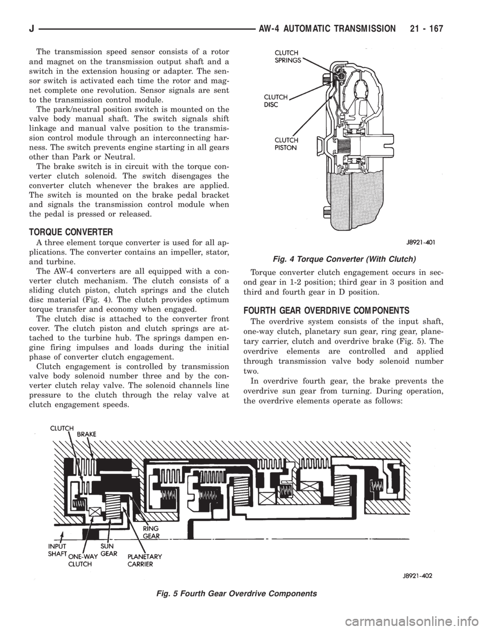
verter clutch mechanism. The clutch consists of a
sliding clutch piston, clutch springs and the clutch
disc material (Fig. 4). The clutch provides optimum
torque transfer and economy when engaged.
The clutch disc is attached to the converter front
cover. The clutch piston and clutch springs are at-
tached to the turbine hub. The springs dampen en-
gine firing impulses and loads during the initial
phase of converter clutch engagement.
Clutch engagement is controlled by transmission
valve body solenoid number three and by the con-
verter clutch relay valve. The solenoid channels line
pressure to the clutch through the relay valve at
clutch engagement speeds.Torque converter clutch engagement occurs in sec-
ond gear in 1-2 position; third gear in 3 position and
third and fourth gear in D position.
FOURTH GEAR OVERDRIVE COMPONENTS
The overdrive system consists of the input shaft,
one-way clutch, planetary sun gear, ring gear, plane-
tary carrier, clutch and overdrive brake (Fig. 5). The
overdrive elements are controlled and applied
through transmission valve body solenoid number
two.
In overdrive fourth gear, the brake prevents the
overdrive sun gear from turning. During operation,
the overdrive elements operate as follows:
Fig. 4 Torque Converter (With Clutch)
Fig. 5 Fourth Gear Overdrive Components
JAW-4 AUTOMATIC TRANSMISSION 21 - 167
Page 1731 of 2158
The rear planetary ring gear is splined to the out-
put shaft. The front planetary carrier and rear car-
rier ring gear are meshed and rotate as a unit with
the output shaft.
GEARTRAIN OPERATION AND APPLICATION
CHARTS
Operation and application of the first through
fourth and reverse gear elements are outlined in the
function and application charts.
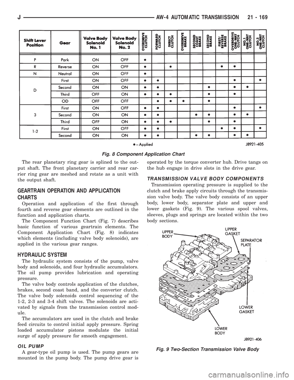
The Component Function Chart (Fig. 7) describes
basic function of various geartrain elements. The
Component Application Chart (Fig. 8) indicates
which elements (including valve body solenoids), are
applied in the various gear ranges.
HYDRAULIC SYSTEM
The hydraulic system consists of the pump, valve
body and solenoids, and four hydraulic accumulators.
The oil pump provides lubrication and operating
pressure.
The valve body controls application of the clutches,
brakes, second coast band, and the converter clutch.
The valve body solenoids control sequencing of the
1-2, 2-3 and 3-4 shift valves. The solenoids are acti-
vated by signals from the transmission control mod-
ule.
The accumulators are used in the clutch and brake
feed circuits to control initial apply pressure. Spring
loaded accumulator pistons modulate the initial
surge of apply pressure for smooth engagement.
OIL PUMP
A gear-type oil pump is used. The pump gears are
mounted in the pump body. The pump drive gear isoperated by the torque converter hub. Drive tangs on
the hub engage in drive slots in the drive gear.
TRANSMISSION VALVE BODY COMPONENTS
Transmission operating pressure is supplied to the
clutch and brake apply circuits through the transmis-
sion valve body. The valve body consists of an upper
body, lower body, separator plate and upper and
lower gaskets (Fig. 9). The various spool valves,
sleeves, plugs and springs are located within the two
body sections.
Fig. 8 Component Application Chart
Fig. 9 Two-Section Transmission Valve Body
JAW-4 AUTOMATIC TRANSMISSION 21 - 169
Page 1739 of 2158
(2) Verify transmission throttle cable operation.
Repair or replace cable if necessary.
(3) Check engine throttle operation. Operate accel-
erator pedal and observe injector throttle plate move-
ment. Adjust linkage if throttle plate does not reach
wide open position.
(4) Check transmission fluid level when fluid is at
normal operating temperature. Start engine. Shift
transmission through all gear ranges then back to
Neutral. Correct level is to Full or Add mark on dip-
stick with engine at curb idle speed.
(5) Check and adjust park/neutral position switch
if necessary.
(6) Check throttle position sensor adjustment and
operation. Adjust the sensor if necessary.
MANUAL SHIFTING TEST
(1) This test determines if problem is related to
mechanical or electrical component.
(2) Stop engine and disconnect transmission con-
trol module or module fuse.
(3) Road test vehicle. Shift transmission into each
gear range. Transmission should operate as follows:
²lock in Park
²back up in Reverse
²not move in Neutral
²provide first gear only with shift lever in 1-2 posi-
tion
²operate in third gear only with shift lever in 3 po-
sition
²operate in overdrive fourth gear in D position
(4) If transmission operates as described, proceed
to next step. However, if forward gear ranges were
difficult to distinguish (all feel the same), or vehicle
would not back up, refer to diagnosis charts. Do not
perform stall or time lag tests.
CAUTION: Do not overspeed the engine during the
next test step. Ease off the throttle and allow the
vehicle to slow before downshifting.
(5) Continue road test. Manually downshift trans-
mission from D to 3, and from 3 to 1-2 position. Then
manually upshift transmission through forward
ranges again.
(6) If transmission operation is OK, perform stall,
time lag and pressure tests. If transmission shifting
problem is encountered, refer to diagnosis charts.
(7) If a problem still exists, continue testing with
DRB scan tool.
HYDRAULIC PRESSURE TEST
PRESSURE TEST PROCEDURE
(1) Connect pressure test gauge to test port on pas-
senger side of transmission. Use Adapter 7554 to con-
nect gauge. Be sure test gauge has minimum
capacity of 300 psi (2100 kPa).(2) Be sure transmission fluid is at normal operat-
ing temperature.
(3) Apply parking brakes and block wheels.
WARNING: DO NOT ALLOW ANYONE TO STAND
AT THE FRONT OR REAR OF THE VEHICLE WHILE
PERFORMING THE FOLLOWING STEPS IN THE
PRESSURE TEST.
(4) Check and adjust engine curb idle speed.
(5) Apply (and hold) service brakes.
(6) Shift transmission into D range and note line
pressure with engine at curb idle speed. Pressure
should be 61-to-70 psi (421-to-481 kPa).
(7) Press accelerator pedal to wide open throttle
position and note line pressure. Pressure should be
173-to-209 psi (1196-to-1442 kPa).
CAUTION: Do not hold wide open throttle for more
than 3-4 seconds at a time.
(8) Shift transmission into Reverse and note line
pressure with engine at curb idle speed. Pressure
should be 75-to-90 psi (519-to-618 kPa).
(9) Press accelerator to wide open throttle position
and note line pressure in Reverse. Pressure should
be 213-to-263 psi (1471-to-1814 kPa).
CAUTION: Do not hold wide open throttle for more
than 4 seconds.
(10) If line pressure is not within specifications,
adjust transmission throttle cable and repeat pres-
sure test.
Fig. 27 Pressure Test Gauge Connection
JAW-4 TRANSMISSION DIAGNOSIS 21 - 177
Page 1740 of 2158
PRESSURE TEST ANALYSIS
If pressures in D and Reverse are higher than
specified in test, check for the following:
²throttle cable loose, worn, binding or out of adjust-
ment
²throttle valve, downshift plug, throttle cam, or pri-
mary regulator valve are sticking, worn or damaged
If pressures in D and Reverse are lower than spec-
ified in test, check for following:
²throttle cable loose, worn, binding or out of adjust-
ment
²throttle valve, downshift plug, or throttle cam
sticking, worn or damaged
²primary regulator valve sticking, worn, or dam-
aged
²oil pump gears or housing worn, or damaged
²overdrive clutch worn, or damaged
If pressures are low in D range only, check for fol-
lowing:
²forward clutch worn or damaged
²fluid leakage in D range circuit (component seal
and O-rings)
If pressures are low in Reverse only, check for fol-
lowing:
²shift cable and manual valve out of adjustment
²fluid leakage in reverse circuit (component seal
and O-rings)
²direct clutch worn or damaged
²first/reverse brake worn or damaged
TORQUE CONVERTER STALL TEST
Stall testing checks the holding ability of the trans-
mission clutches and brakes and of the torque con-
verter stator overrunning clutch.Stall speeds are
checked in both Drive and Reverse ranges with
the AW-4 transmission.
(1) Before starting test, be sure fluid level is cor-
rect and fluid is at normal operating temperature.
(2) Connect tachometer to engine. Position tachom-
eter so it can be viewed from drivers seat.
(3) Apply parking brakes and block wheels.
(4) Apply and hold service brakes.
(5) Shift transfer case into 2H position.
(6) Start engine.
WARNING: DO NOT ALLOW ANYONE TO STAND AT
THE FRONT OR REAR OF THE VEHICLE DURING
THE TEST.
(7) Shift transmission into D range.
(8) Open throttle completely and record maximum
engine rpm registered on tachometer. It takes any-
where from 4 to 10 seconds to reach maximum rpm.
However, once maximum rpm has been achieved,do
not hold wide open throttle for more than 3-4
seconds.CAUTION: Stalling the converter causes a rapid in-
crease in fluid temperature. To avoid fluid overheat-
ing, hold wide open throttle for no more than 4
seconds after reaching peak rpm. In addition, if
more than one stall test is required, run the engine
at 1000 rpm with the transmission in Neutral for at
least 20 seconds to cool the fluid.
(9) Stall speed should be in 2100-2400 rpm range
in Drive.
(10) Release throttle, shift transmission into Neu-
tral, and run engine for 20-30 seconds to cool fluid.
(11) Shift transmission into Reverse.
(12) Repeat stall test described in step (8).
(13) Stall speed in Reverse should also be in 2100-
2400 rpm range.
(14) Release accelerator pedal, shift transmission
into Neutral, and run engine for 20-30 seconds to
cool fluid.
STALL SPEED TEST ANALYSIS
If engine rpm is lower than specified in D and Re-
verse, check for the following:
²engine output/performance insufficient
²stator overrunning clutch in torque converter not
holding if engine speed was 1500 rpm or less.
If stall speed in D range is higher than specified,
check for the following:
²line pressure low
²forward clutch slipping
²No. 2 one-way clutch not holding
²overdrive one-way clutch not holding
If stall speed in Reverse was higher than specified,
check for the following:
²line pressure low
²direct clutch slipping
²first/ reverse brake slipping
²overdrive one-way clutch not holding
If stall speeds were higher than specified in both D
and Reverse, check for the following:
²low fluid level
²line pressure low
²overdrive one-way clutch not holding
TIME LAG TEST
This test checks general condition of the overdrive
clutch, forward clutch, rear clutch and first/reverse
brake. Condition is indicated by the amount of time
required for clutch/brake engagement with the en-
gine at curb idle speed. Engagement time is mea-
sured for D and Reverse positions. A stop watch is
recommended for test accuracy.
TEST PROCEDURE
(1) Check and adjust transmission fluid level if
necessary.
(2) Bring transmission to normal operating tem-
perature.
21 - 178 AW-4 TRANSMISSION DIAGNOSISJ
Page 1907 of 2158
WHEELS AND TIRES
CONTENTS
page page
SPECIFICATIONS........................ 12
TIRES.................................. 1VEHICLE VIBRATION..................... 10
WHEELS................................ 6
TIRES
INDEX
page page
Cleaning of Tires.......................... 2
General Information........................ 1
Pressure Gauges.......................... 2
Repairing Leaks........................... 3
Replacement Tires......................... 2Rotation................................. 3
Tire Inflation Pressures...................... 2
Tire Noise or Vibration...................... 4
Tire Wear Patterns......................... 4
Tread Wear Indicators....................... 3
GENERAL INFORMATION
Tires are designed for each specific vehicle. They
provide the best overall performance for normal oper-
ation. The ride and handling characteristics match
the vehicle's requirements. With proper care they
will give excellent reliability, traction, skid resis-
tance, and tread life. These tires have specific load
carrying capacities. When correctly inflated, they will
operate properly.
Tires used in cool climates, and with light loads
will have a longer life than tires used in hot climates
with heavy loads. Abrasive road surfaces will acceler-
ate tire wear.
Driving habits have more effect on tire life than
any other factor. Careful drivers will obtain much
greater mileage than careless drivers.
Driving habits that shorten the life of any tire;
²Rapid acceleration and deceleration
²Severe application of brakes
²High-speed driving
²Taking turns at excessive speeds
²Striking curbs and other obstacles
It is very important to follow the tire rotation in-
terval
IDENTIFICATION
Tire type, size, aspect ratio and speed rating are
encoded in the letters and numbers imprinted on the
side wall of the tire. Refer to the chart to decipher
the tire identification code (Fig. 1).Performance tires will have a speed rating letter
after the aspect ratio number. The speed rating is not
always printed on the tire sidewall. The letterSin-
dicates that the tire is speed rated up to 112 mph.
²Qup to 100 mph
²Tup to 118 mph
²Uup to 124 mph
²Hup to 130 mph
²Vup to 149 mph
²Zmore than 149 mph (consult the tire manufac-
turer for the specific speed rating)
An All Season type tire will have eitherM+S,M
&SorMÐS(indicating mud and snow traction) im-
printed on the side wall.
RADIAL-PLY TIRES
Radial-ply tires improve handling, tread life, ride
quality and decrease rolling resistance.
Radial-ply tires must always be used in sets of
four. Under no circumstances should they be used on
the front only. They may be mixed with temporary
spare tires when necessary, but reduced speeds are
recommended.
Radial-ply tires have the same load-carrying capac-
ity as other types of tires of the same size. They use
the same recommended inflation pressures.
SPARE TIRE (TEMPORARY)
The compact spare tire is designed for emergency
use only. The original tire should be repaired and re-
installed at the first opportunity. Refer to Owner's
Manual for complete details.
JWHEELS AND TIRES 22 - 1
Page 2125 of 2158
- XJ, ANTENNA REMOVE/INSTALL........8F-8
- XJ, GENERAL INFORMATION...........8K-1
- XJ, MULTI-FUNCTION SWITCH..........8J-4
- XJ, MULTI-FUNCTION SWITCH
REMOVE/INSTALL.....................8J-5
- XJ, RADIO REMOVE/INSTALL...........8F-6
- XJ, SOUND BAR REMOVE/INSTALL......8F-8
- XJ, SPEAKERS REMOVE/INSTALL........8F-6
- XJ, TURN SIGNAL/HAZARD WARNING
SYSTEM.............................8J-3
- YJ, ANTENNA REMOVE/INSTALL.......8F-10
- YJ, BUZZER MODULE SCHEMATIC......8U-4
- YJ, GENERAL INFORMATION..........8K-10
- YJ, HAZARD WARNING SYSTEM........8J-4
- YJ, RADIO REMOVE/INSTALL...........8F-9
- YJ, SERVICE PROCEDURES...........8K-17
- YJ, SOUND BAR REMOVE/INSTALL.....8F-10
- YJ, SPEAKERS REMOVE/INSTALL........8F-9
- YJ, TURN SIGNAL SYSTEM............8J-3
- YJ, TURN SIGNAL/HAZARD WARNING
SWITCH REMOVE/INSTALL..............8J-5
30RH/32RH AUTOMATIC TRANSMISSION . . 21-67
30RH/32RH GENERAL SPECIFICATIONS . . 21-335
30RH/32RH IN-VEHICLE SERVICE........21-99
30RH/32RH PRESSURE TEST
SPECIFICATIONS....................21-336
30RH/32RH TORQUE SPECIFICATIONS . . . 21-336
30RH/32RH TRANSMISSION DIAGNOSIS . . 21-70
30RH/32RH TRANSMISSION OVERHAUL . 21-119
30RH/32RH TRANSMISSION REMOVAL
AND INSTALLATION..................21-115
4-CYLINDER ENGINE, ENGINE FIRING
ORDERÐ2.5L.......................8D-32
60-WAY CONNECTOR, POWERTRAIN
CONTROL MODULE (PCM).............14-40
6-CYLINDER ENGINE, AUXILIARY
ELECTRIC COOLING FANÐXJ MODELS
WITH 4.0L...........................7-35
6-CYLINDER ENGINE, ENGINE FIRING
ORDERÐ4.0L.......................8D-32
ABS BRAKE DIAGNOSIS.................5-3
ABS COMPONENT SERVICEABILITY.......5-37
ABS DIAGNOSTIC CONNECTOR.......5-35,5-3
ABS OPERATION AND SERVICE..........5-33
ABS POWER RELAY; ANTI-LOCK BRAKES
(XJ).............................8W-32-1
ABS POWER RELAY; ANTI-LOCK BRAKES
(XJ-RHD).........................8W-32-1
ABS POWER RELAY; ANTI-LOCK BRAKES
(YJ).............................8W-32-1
ABS PUMP MOTOR RELAY; ANTI-LOCK
BRAKES (XJ)......................8W-32-1
ABS PUMP MOTOR RELAY; ANTI-LOCK
BRAKES (XJ-RHD).................8W-32-1
ABS PUMP MOTOR RELAY; ANTI-LOCK
BRAKES (YJ)......................8W-32-1
ABS SYSTEM POWER-UP AND
INITIALIZATION.......................5-35
ABS WARNING LAMP; ANTI-LOCK
BRAKES (XJ)......................8W-32-2
ABS WARNING LAMP; ANTI-LOCK
BRAKES (XJ-RHD).................8W-32-2
ABS WARNING LAMP; ANTI-LOCK
BRAKES (YJ)
......................8W-32-2
ABS WARNING LAMP; INSTRUMENT
CLUSTER (XJ)
.....................8W-40-2
ABS WARNING LAMP; INSTRUMENT
CLUSTER (XJ-RHD)
................8W-40-2
ABS WARNING LAMP; INSTRUMENT
CLUSTER (YJ)
.....................8W-40-2
ABS WARNING LIGHT DISPLAY
...........5-3
ABSOLUTE PRESSURE (MAP) SENSOR,
MANIFOLD; FUEL SYSTEM
.............14-63
ABSOLUTE PRESSURE (MAP) SENSOR,
MANIFOLD; FUEL/IGNITION (YJ)
......8W-30-4
ABSOLUTE PRESSURE (MAP) SENSOR,
MANIFOLD; IGNITION SYSTEMS
....8D-23,8D-5
ABSOLUTE PRESSURE (MAP) SENSOR
TEST, MANIFOLD; FUEL SYSTEM
........14-47
ABSOLUTE PRESSURE (MAP) SENSOR
TEST, MANIFOLD; IGNITION SYSTEMS
....8D-11
ABSOLUTE PRESSURE (MAP)
SENSORÐPCM INPUT, MANIFOLD
.......14-23
ABSOLUTE PRESSURE SENSOR,
MANIFOLD; FUEL/IGNITION (XJ)
......8W-30-4
ABSOLUTE PRESSURE SENSOR,
MANIFOLD; FUEL/IGNITION (XJ-RHD)
. . 8W-30-4ABSORBER, SHOCK; FRONT
SUSPENSION AND AXLE............2-13,2-16
ABSORBER, SHOCK; REAR SUSPENSION
AND AXLES........................3-4,3-7
A/C BLOWER MOTOR.................24-35
A/C COMPONENTS....................24-4
A/C COMPRESSOR; AIR CONDITIONING/
HEATER (YJ)......................8W-42-2
A/C COMPRESSOR CLUTCH............24-15
A/C COMPRESSOR CLUTCH RELAY . 24-15,24-16
A/C CONDENSER.....................24-34
A/C CONTROL REPLACEMENT, HEATER . . . 24-23
A/C OPERATION, HEATER...............24-1
A/C RECIRCULATING DOOR VACUUM
MOTOR REPLACEMENT...............24-27
ACCELERATION SWITCH; ANTI-LOCK
BRAKES (XJ)......................8W-32-1
ACCELERATION SWITCH; ANTI-LOCK
BRAKES (XJ-RHD).................8W-32-1
ACCELERATION SWITCH; ANTI-LOCK
BRAKES (YJ)......................8W-32-1
ACCELERATION SWITCH; BRAKES........5-35
ACCELERATION SWITCH INSTALLATION....5-39
ACCELERATION SWITCH OPERATION......5-37
ACCELERATION SWITCH REMOVAL.......5-39
ACCELERATOR PEDAL.................14-17
ACCELERATOR PEDAL AND THROTTLE
CABLE........................14-17,14-58
ACCESSORY DRIVE BELT...............0-21
ACCESSORY DRIVE BELTS, ENGINE.......7-38
ACCESSORY LAMP AND HEATER
CONTROL PANEL LAMP; INTERIOR
LIGHTING (YJ)....................8W-44-1
ACCUMULATOR PISTONS AND SPRINGS . 21-189
A/C-HEATER BLOWER MOTOR; AIR
CONDITIONING/HEATER (YJ).........8W-42-2
A/C-HEATER SYSTEM; AIR
CONDITIONING/HEATER (XJ).........8W-42-1
A/C-HEATER SYSTEM; AIR
CONDITIONING/HEATER (XJ-RHD).....8W-42-1
ADD-A-TRUNKÐYJ..................23-157
ADJUSTER/MOTORS, POWER SEAT . . . 8R-1,8R-2
ADJUSTER/MOTORS REMOVE/INSTALL,
POWER SEAT........................8R-3
ADJUSTMENT, BRAKELIGHT SWITCH......5-32
ADJUSTMENT, COMPASS VARIATION......8C-5
ADJUSTMENT, DIFFERENTIAL SHIM
PACK MEASUREMENT..................2-43
ADJUSTMENT, DRUM BRAKE............5-57
ADJUSTMENT, FRONT BAND...........21-102
ADJUSTMENT, GEARSHIFT CABLE/
LINKAGE...........................21-71
ADJUSTMENT, PARK INTERLOCK CABLE . 21-195
ADJUSTMENT PROCEDURES,
TRANSMISSION ASSEMBLY...........21-155
ADJUSTMENT, REAR WHEEL SENSOR
INSTALLATION........................5-38
ADJUSTMENT, SHIFT CABLE...........21-195
ADJUSTMENT, SHIFT LINKAGE . . . 21-286,21-309
ADJUSTMENT, TRANSMISSION
THROTTLE CABLE...................21-194
ADJUSTMENT, TRANSMISSION
THROTTLE VALVE CABLE..............21-71
ADJUSTMENT, VALVE BODY ASSEMBLY . . 21-153
ADJUSTMENT (XJ), PARK INTERLOCK
CABLE............................21-101
ADJUSTMENT (XJ), SHIFT CABLE.......21-100
ADJUSTMENT (XJ/YJ), PARKING BRAKE
CABLE TENSIONER....................5-69
ADJUSTMENT (XJ/YJ), THROTTLE VALVE
CABLE............................21-101
ADJUSTMENT (YJ), SHIFT LINKAGE.....21-100
ADJUSTMENTÐMAJOR, DOOR
ALIGNMENT.........................23-41
ADJUSTMENTÐMINOR, DOOR
ALIGNMENT.........................23-37
ADJUSTMENTÐXJ, DOOR LATCH........23-48
ADJUSTMENTÐXJ, HOOD.............23-10
ADJUSTMENTÐXJ, LIFTGATE...........23-63
ADJUSTMENTÐYJ, TAILGATE..........23-121
ADJUSTMENTS, ALIGNMENT
MEASUREMENTS
......................2-8
ADJUSTMENTS, STEERING GEAR
........19-24
AFTERMARKET PAINT AND TRIM
REPAIR PRODUCTSÐXJ
..............23-159
AFTERMARKET PAINT AND TRIM
REPAIR PRODUCTSÐYJ
..............23-160
AIR CLEANER
.......................14-29AIR CLEANER ELEMENT; EMISSION
CONTROL SYSTEMS...................25-7
AIR CLEANER ELEMENT; FUEL SYSTEM . . . 14-59
AIR CLEANER ELEMENT; LUBRICATION
AND MAINTENANCE...................0-18
AIR CLEANER HOUSING...............14-58
AIR CONDITIONING...................24-37
AIR CONDITIONING (A/C) CLUTCH
RELAY.............................14-58
AIR CONDITIONING (A/C) CLUTCH
RELAYÐPCM OUTPUT................14-26
AIR CONDITIONING (A/C) CONTROLSÐ
PCM INPUT.........................14-21
AIR CONDITIONING CONTROLSÐXJ
VEHICLES..........................24-15
AIR CONDITIONING CONTROLSÐYJ
VEHICLES..........................24-16
AIR CONDITIONING, HEATER; AIR
CONDITIONING/HEATER (YJ).........8W-42-2
AIR CONDITIONING OPERATION; AIR
CONDITIONING/HEATER (XJ).........8W-42-2
AIR CONDITIONING OPERATION; AIR
CONDITIONING/HEATER (XJ-RHD).....8W-42-2
AIR CONDITIONING PERFORMANCE
TESTS.............................24-12
AIR CONDITIONING SCHEMATICÐXJ......24-5
AIR CONDITIONING TEST PROCEDURES,
HEATING...........................24-15
AIR CONTROL (IAC) MOTOR, IDLE; FUEL
SYSTEM............................14-62
AIR CONTROL (IAC) MOTOR, IDLE;
FUEL/IGNITION (XJ)................8W-30-2
AIR CONTROL (IAC) MOTOR, IDLE;
FUEL/IGNITION (YJ)................8W-30-2
AIR CONTROL (IAC) MOTOR, IDLE;
FUEL/IGNITION (XJ-RHD)............8W-30-2
AIR CONTROL (IAC) MOTORÐPCM
OUTPUT, IDLE.......................14-27
AIR CONTROL MOTOR TEST, IDLE.......14-49
AIR DEFLECTORÐXJ, COWL
WEATHERSTRIP SEAL/CROSSMEMBER . . . 23-11
AIR DOOR VACUUM MOTOR, FRESH.....24-34
AIR EXHAUST GRILLEÐXJ.............23-25
AIR GAP, SPEED SENSOR...............5-37
AIR INTAKE DUCT, FRESH..............24-34
AIR PRESSURE TEST.................21-74
AIR TEMPERATURE SENSOR, INTAKE;
FUEL/IGNITION (XJ)................8W-30-4
AIR TEMPERATURE SENSOR, INTAKE;
FUEL/IGNITION (YJ)................8W-30-4
AIR TEMPERATURE SENSOR, INTAKE;
FUEL/IGNITION (XJ-RHD)............8W-30-4
AIR TEMPERATURE SENSOR, INTAKE
MANIFOLD; FUEL SYSTEM.............14-60
AIR TEMPERATURE SENSOR, INTAKE
MANIFOLD; IGNITION SYSTEMS....8D-23,8D-5
AIR TEMPERATURE, SENSOR
RESISTANCE (OHMS)ÐCOOLANT
TEMPERATURE SENSOR/MANIFOLD......14-46
AIR TEMPERATURE SENSOR TEST,
INTAKE MANIFOLD; FUEL SYSTEM.......14-46
AIR TEMPERATURE SENSOR TEST,
INTAKE MANIFOLD; IGNITION
SYSTEMS..........................8D-11
AIR TEMPERATURE SENSORÐPCM
INPUT, INTAKE MANIFOLD.............14-22
AIRBAG MODULE.....................8M-1
AIRBAG MODULE HANDLING............8M-2
AIRBAG MODULE REMOVE/INSTALL......8M-3
AIRBAG MODULE REMOVEÐINSTALL....19-49
AIRBAG SYSTEM; RESTRAINT SYSTEMS . . 8M-1
AIRBAG SYSTEM; STEERING...........19-47
AIRBAG SYSTEM SERVICE (DEPLOYED) . . . 8M-2
AIR-CONDITIONER COMPRESSOR........0-21
ALIGNMENT ADJUSTMENTÐMAJOR,
DOOR.............................23-41
ALIGNMENT ADJUSTMENTÐMINOR,
DOOR.............................23-37
ALIGNMENT, FRONT WHEEL..............2-5
ALIGNMENTÐXJ, HEADLAMP...........8L-6
ALIGNMENTÐYJ, HEADLAMP
..........8L-22
ALIGNMENTÐYJ, HOOD
..............23-107
ANCHOR AND BUMPERÐXJ, LIFTGATE
LICENSE PLATE SCREW
...............23-65
ANGLE, GROUND CLEARANCE AND
RAMP
..............................0-11
ANGLE MEASUREMENT, UNIVERSAL
JOINT
..............................16-4
JINDEX 1
Description Group-Page Description Group-Page Description Group-Page