1995 JEEP YJ front brakes
[x] Cancel search: front brakesPage 194 of 2158
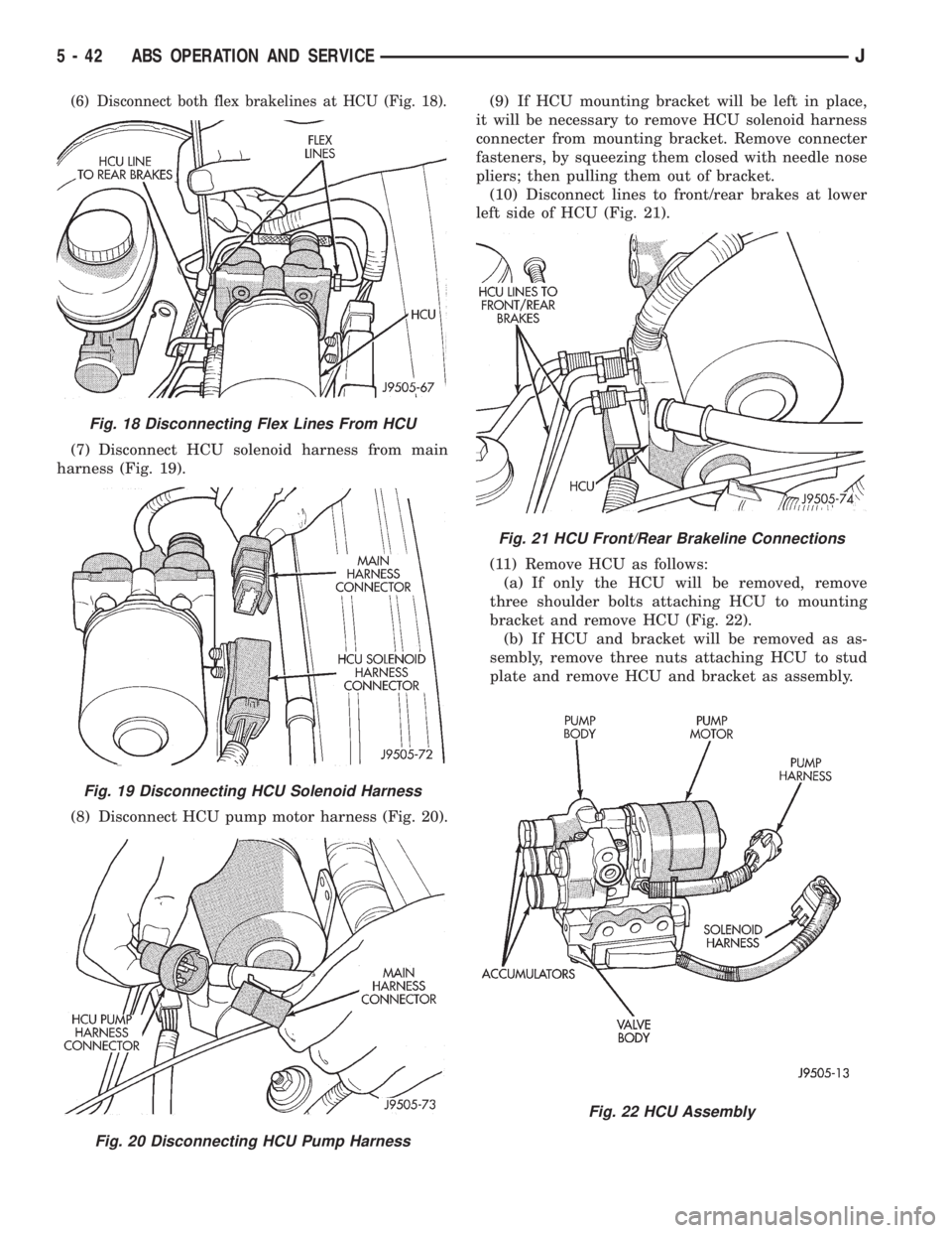
(6) Disconnect both flex brakelines at HCU (Fig. 18).
(7) Disconnect HCU solenoid harness from main
harness (Fig. 19).
(8) Disconnect HCU pump motor harness (Fig. 20).(9) If HCU mounting bracket will be left in place,
it will be necessary to remove HCU solenoid harness
connecter from mounting bracket. Remove connecter
fasteners, by squeezing them closed with needle nose
pliers; then pulling them out of bracket.
(10) Disconnect lines to front/rear brakes at lower
left side of HCU (Fig. 21).
(11) Remove HCU as follows:
(a) If only the HCU will be removed, remove
three shoulder bolts attaching HCU to mounting
bracket and remove HCU (Fig. 22).
(b) If HCU and bracket will be removed as as-
sembly, remove three nuts attaching HCU to stud
plate and remove HCU and bracket as assembly.
Fig. 18 Disconnecting Flex Lines From HCU
Fig. 19 Disconnecting HCU Solenoid Harness
Fig. 20 Disconnecting HCU Pump Harness
Fig. 21 HCU Front/Rear Brakeline Connections
Fig. 22 HCU Assembly
5 - 42 ABS OPERATION AND SERVICEJ
Page 195 of 2158
HCU INSTALLATION (XJ)
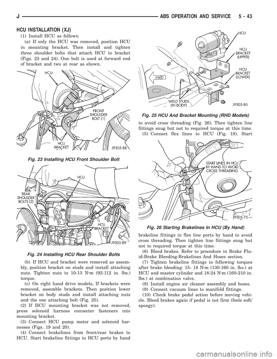
(1) Install HCU as follows:
(a) If only the HCU was removed, position HCU
in mounting bracket. Then install and tighten
three shoulder bolts that attach HCU to bracket
(Figs. 23 and 24). One bolt is used at forward end
of bracket and two at rear as shown.
(b) If HCU and bracket were removed as assem-
bly, position bracket on studs and install attaching
nuts. Tighten nuts to 10-13 Nzm (92-112 in. lbs.)
torque.
(c) On right hand drive models, If brackets were
removed, assemble brackets. Then position lower
bracket on body studs and install attaching nuts
and the one attaching bolt (Fig. 25).
(2) If HCU mounting bracket was not removed,
press solenoid harness connecter fasteners into
mounting bracket.
(3) Connect HCU pump motor and solenoid har-
nesses (Figs. 19 and 20).
(4) Connect brakelines from front/rear brakes to
HCU. Start brakeline fittings in HCU ports by handto avoid cross threading (Fig. 26). Then tighten line
fittings snug but not to required torque at this time.
(5) Connect flex lines to HCU (Fig. 18). Start
brakeline fittings in flex line ports by hand to avoid
cross threading. Then tighten line fittings snug but
not to required torque at this time.
(6) Bleed brakes. Refer to procedure in Brake Flu-
id-Brake Bleeding-Brakelines And Hoses section.
(7) Tighten brakeline fittings to following torques
after brake bleeding: 15- 18 Nzm (130-160 in. lbs.) at
HCU and master cylinder and 18-24 Nzm (160-210 in.
lbs.) at combination valve.
(8) Install engine air cleaner assembly and hoses.
(9) Connect vacuum lines to manifold fittings.
(10) Check brake pedal action before moving vehi-
cle. Bleed brakes again if pedal is not firm (feels soft/
spongy).
Fig. 23 Installing HCU Front Shoulder Bolt
Fig. 24 Installing HCU Rear Shoulder Bolts
Fig. 25 HCU And Bracket Mounting (RHD Models)
Fig. 26 Starting Brakelines In HCU (By Hand)
JABS OPERATION AND SERVICE 5 - 43
Page 196 of 2158
HCU REMOVAL (YJ)
(1) Place shop towels under master cylinder and
HCU brakelines.
(2) Disconnect flex lines at upper part of HCU.
(3) Disconnect solenoid and pump harness wires at
HCU harness connecters.
(4) Disconnect lines to front/rear brakes at lower
part of HCU.
(5) Remove shoulder bolts attaching HCU to
mounting bracket and remove HCU.
HCU INSTALLATION (YJ)
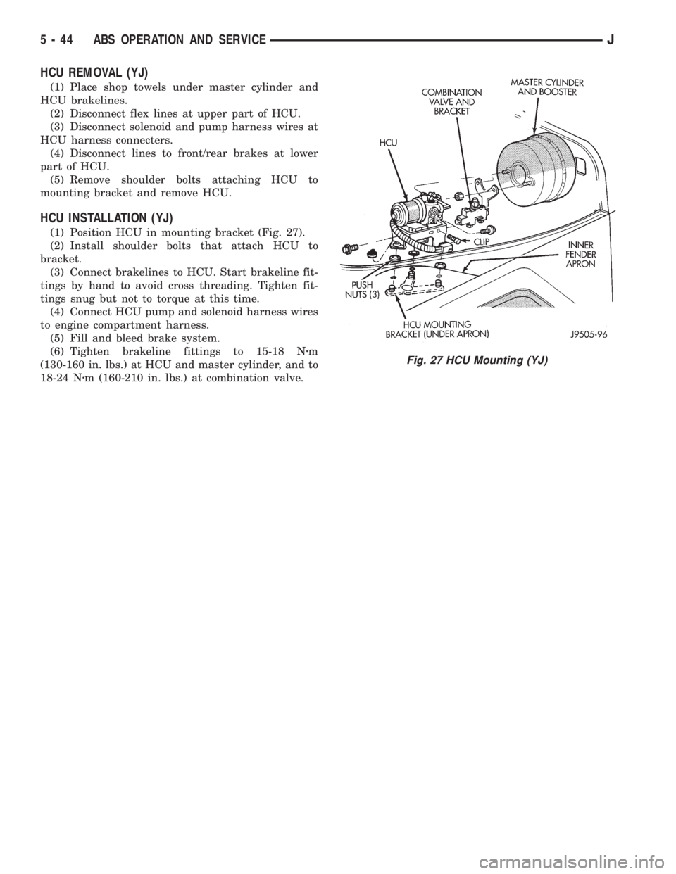
(1) Position HCU in mounting bracket (Fig. 27).
(2) Install shoulder bolts that attach HCU to
bracket.
(3) Connect brakelines to HCU. Start brakeline fit-
tings by hand to avoid cross threading. Tighten fit-
tings snug but not to torque at this time.
(4) Connect HCU pump and solenoid harness wires
to engine compartment harness.
(5) Fill and bleed brake system.
(6) Tighten brakeline fittings to 15-18 Nzm
(130-160 in. lbs.) at HCU and master cylinder, and to
18-24 Nzm (160-210 in. lbs.) at combination valve.
Fig. 27 HCU Mounting (YJ)
5 - 44 ABS OPERATION AND SERVICEJ
Page 198 of 2158
The amount of piston retraction is determined by
brakelining wear. Generally, the amount is just
enough to maintain contact between the piston and
inboard brakeshoe. Brakelining running clearance at
the rotor, will be held between zero and a maximum
of 0.12 mm (0.005 in.).
DISC BRAKESHOE REMOVAL
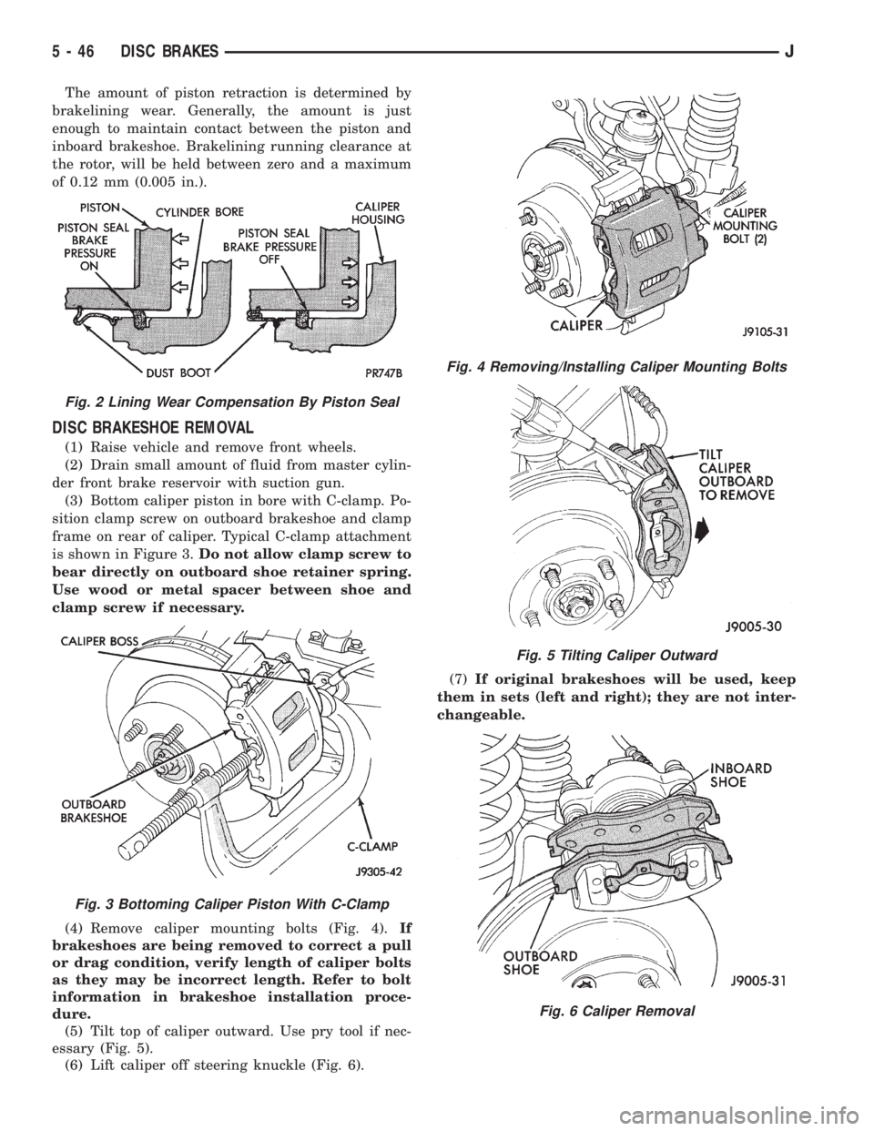
(1) Raise vehicle and remove front wheels.
(2) Drain small amount of fluid from master cylin-
der front brake reservoir with suction gun.
(3) Bottom caliper piston in bore with C-clamp. Po-
sition clamp screw on outboard brakeshoe and clamp
frame on rear of caliper. Typical C-clamp attachment
is shown in Figure 3.Do not allow clamp screw to
bear directly on outboard shoe retainer spring.
Use wood or metal spacer between shoe and
clamp screw if necessary.
(4) Remove caliper mounting bolts (Fig. 4).If
brakeshoes are being removed to correct a pull
or drag condition, verify length of caliper bolts
as they may be incorrect length. Refer to bolt
information in brakeshoe installation proce-
dure.
(5) Tilt top of caliper outward. Use pry tool if nec-
essary (Fig. 5).
(6) Lift caliper off steering knuckle (Fig. 6).(7)If original brakeshoes will be used, keep
them in sets (left and right); they are not inter-
changeable.
Fig. 2 Lining Wear Compensation By Piston Seal
Fig. 3 Bottoming Caliper Piston With C-Clamp
Fig. 4 Removing/Installing Caliper Mounting Bolts
Fig. 5 Tilting Caliper Outward
Fig. 6 Caliper Removal
5 - 46 DISC BRAKESJ
Page 200 of 2158

install caliper over rotor and seat upper ends of
brakeshoes on top mounting ledge (Fig. 11).
CAUTION: Before securing the caliper, be sure the
caliper brake hose is not twisted, kinked or touch-
ing any chassis components. Also be sure the hose
is clear of all suspension and steering components.
Loosen and reposition the hose if necessary.
(8) Install and tighten caliper mounting bolts to
10-20 Nzm (7-15 ft. lbs.) torque.
CAUTION: If new caliper bolts are being installed,
or if the original reason for repair was a drag/pull
condition, check caliper bolt length before proceed-
ing. If the bolts have a shank length greater than
67.6 mm (2.66 in.), they will contact the inboard
brakeshoe causing a partial apply condition. Refer
to Figure 14 for required caliper bolt length.
(9) Install wheels. Tighten lug nuts to 102 Nzm (75
ft. lbs.) torque.
(10) Pump brake pedal until caliper pistons and
brakeshoes are seated.(11) Top off brake fluid level if necessary. Use Mo-
par brake fluid or equivalent meeting SAE J1703 and
DOT 3 standards only.
CALIPER REMOVAL
(1) Raise vehicle and remove front wheels.
(2) Remove fitting bolt and disconnect front brake
hose at caliper. Discard fitting bolt gaskets. They
should not be reused.
(3) Remove caliper mounting bolts (Fig. 4).
(4) Rotate caliper rearward by hand or with pry
tool (Fig. 5). Then rotate caliper and brakeshoes off
mounting ledges.
(5) Remove caliper from vehicle.
CALIPER DISASSEMBLY
(1) Remove brakeshoes from caliper.
Fig. 11 Installing Inboard Brakeshoe
Fig. 12 Installing Outboard Brakeshoe
Fig. 13 Caliper Installation
Fig. 14 Caliper Mounting Bolt Dimensions
5 - 48 DISC BRAKESJ
Page 203 of 2158

CALIPER INSTALLATION
(1) Install brakeshoes in caliper (Figs. 11, 12).
(2) Connect brake hose to caliper but do not
tighten fitting bolt completely at this time.Be sure
to use new gaskets on fitting bolt to avoid leaks
(Fig. 25).
(3) Install caliper. Position mounting notches at
lower end of brakeshoes on bottom mounting ledge
(Fig. 13). Then rotate caliper over rotor and seat
notches at upper end of shoes on mounting ledge
(Fig. 13).
(4) Coat caliper mounting bolts with GE 661 or
Dow 111 silicone grease. Then install and tighten
bolts to 10-20 Nzm (7-15 ft. lbs.) torque.CAUTION: If new caliper bolts are being installed,
or if the original reason for repair was a drag/pull
condition, check caliper bolt length before proceed-
ing. If the bolts have a shank length greater than
67.6 mm (2.66 in.), they may contact the inboard
brakeshoe causing a partial apply condition. Refer
to Figure 14 for the required caliper bolt length.
(5) Position front brake hose clear of all chassis
components and tighten caliper fitting bolt to 31 Nzm
(23 ft. lbs.) torque.
CAUTION: Be sure the brake hose is not twisted or
kinked at any point. Also be sure the hose is clear
of all steering and suspension components. Loosen
and reposition the hose if necessary.
(6) Install wheels. Tighten wheel lug nuts to 109-
150 Nzm (80-110 ft. lbs.) torque.
(7) Fill and bleed brake system. Refer to proce-
dures in Service Adjustments section.
ROTOR REMOVAL
(1) Raise vehicle and remove wheel.
(2) Remove caliper.
(3) Remove retainers securing rotor to hub studs
(Fig. 26).
(4) Remove rotor from hub (Fig. 26).
(5) If rotor shield requires service, remove front
hub and bearing assembly.
ROTOR INSTALLATION
(1) If new rotor is being installed, remove protec-
tive coating from rotor surfaces with Mopar carb
cleaner.It is not necessary to machine a rotor to
remove the coating. Mopar carb cleaner fol-
lowed by a rinse with brake cleaner will re-
move the coating.
(2) Install rotor on hub.
(3) Install caliper.
Fig. 23 Installing Caliper Piston
Fig. 24 Seating Caliper Piston Dust Boot
Fig. 25 Front Brake Hose And Fitting Components
JDISC BRAKES 5 - 51
Page 212 of 2158
PARKING BRAKES
INDEX
page page
General Service Information................. 60
Parking Brake Cable Tensioner Adjustment (XJ/YJ).. 68
Parking Brake Cable Tensioner Replacement (XJ) . 65
Parking Brake Front Cable Replacement (YJ).... 67
Parking Brake Lever Installation (XJ with Full
Console).............................. 64
Parking Brake Lever Installation (XJ with Mini
Console).............................. 63
Parking Brake Lever Installation (XJ Without
Console).............................. 65Parking Brake Lever Removal (XJ with Full Console).63
Parking Brake Lever Removal (XJ with Mini
Console).............................. 62
Parking Brake Lever Removal (XJ Without Console).64
Parking Brake Operation.................... 60
Parking Brake Pedal Installation (YJ)........... 66
Parking Brake Pedal Removal (YJ)............ 66
Parking Brake Rear Cable Replacement (XJ)..... 66
Parking Brake Rear Cable Replacement (YJ)..... 68
Parking Brake Switch...................... 68
GENERAL SERVICE INFORMATION
Parking brake adjustment is controlled by a cable ten-
sioner mechanism.
The cable tensioner, once adjusted at the factory,
should not need further adjustment under normal
circumstances. There are only two instances when
adjustment is required. The first is when a new ten-
sioner, or cables have been installed. And the second,
is when the tensioner and cables are disconnected for
access to other brake components.
PARKING BRAKE OPERATION
The rear brakes are utilized for the parking brake
function. They are actuated hydraulically during nor-
mal brake operation but are mechanically actuated
for parking brake operation.
Parking Brake Components
The rear brakeshoes are applied by a system of le-
vers and cables for parking brake operation. A foot or
hand operated lever in the passenger compartment is
the main application device. Actuating levers on the
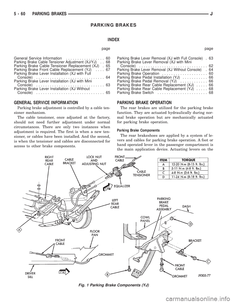
Fig. 1 Parking Brake Components (YJ)
5 - 60 PARKING BRAKESJ
Page 213 of 2158
secondary brakeshoes move the shoes directly into
contact with the drum braking surface. The actuating
levers are interconnected by a system of cables and a
tensioner mechanism. The tensioner mechanism con-
trols parking brake adjustment.
A parking brake switch is used on all models. It is
mounted on the parking brake lever or foot pedal and
is actuated by movement of the lever/pedal. The
switch, which is in circuit with the red warning light
in the dash, will illuminate the warning light when-
ever the parking brakes are applied.
On XJ models, the cable tensioner is part of the lever
assembly. On YJ models, the tensioner and equalizer
are mounted in a bracket attached to the underbody.
On YJ models, the parking brake front cable is at-
tached to the foot pedal and cable tensioner. The ten-
sioner and rear cables are connected to the equalizer
(Fig. 1).
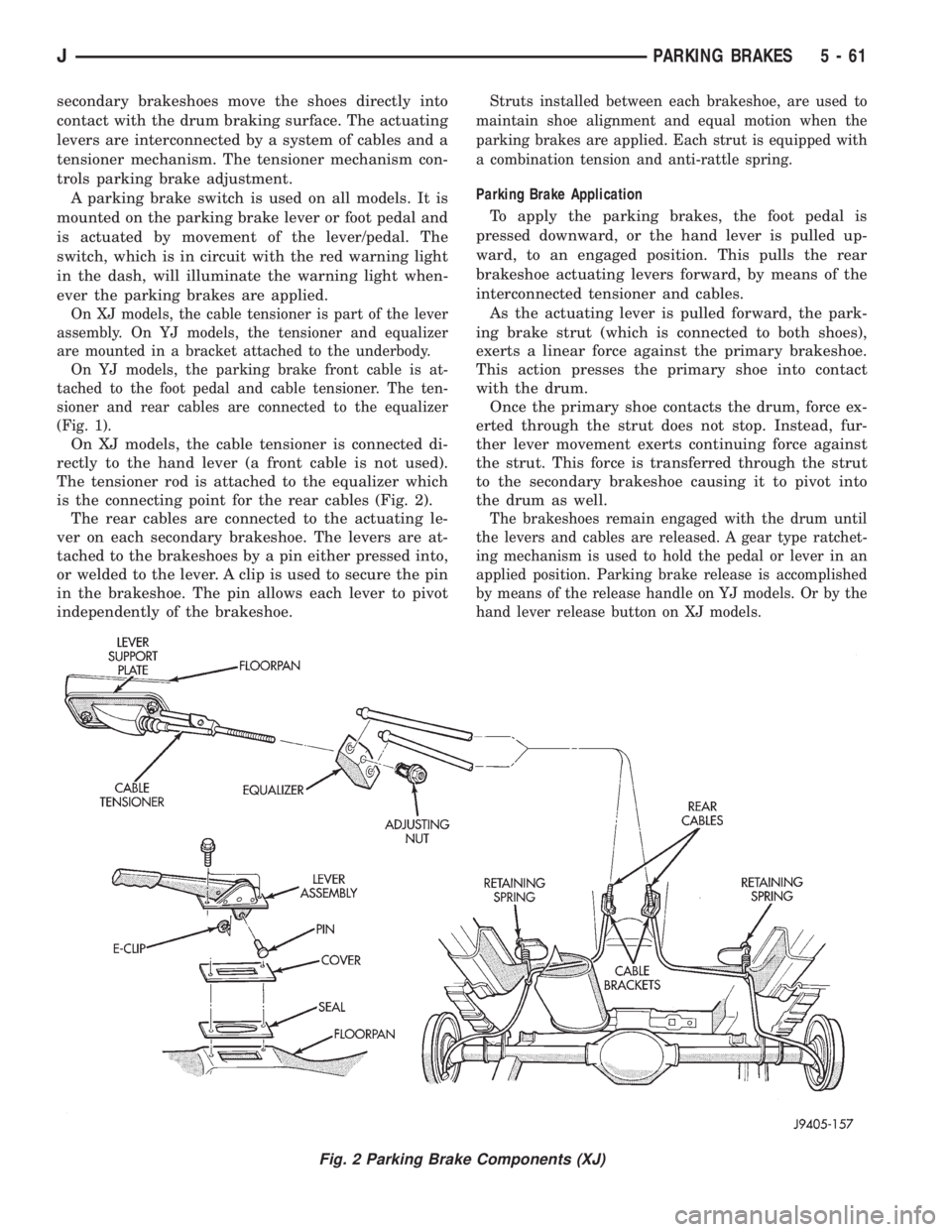
On XJ models, the cable tensioner is connected di-
rectly to the hand lever (a front cable is not used).
The tensioner rod is attached to the equalizer which
is the connecting point for the rear cables (Fig. 2).
The rear cables are connected to the actuating le-
ver on each secondary brakeshoe. The levers are at-
tached to the brakeshoes by a pin either pressed into,
or welded to the lever. A clip is used to secure the pin
in the brakeshoe. The pin allows each lever to pivot
independently of the brakeshoe.
Struts installed between each brakeshoe, are used to
maintain shoe alignment and equal motion when the
parking brakes are applied. Each strut is equipped with
a combination tension and anti-rattle spring.
Parking Brake Application
To apply the parking brakes, the foot pedal is
pressed downward, or the hand lever is pulled up-
ward, to an engaged position. This pulls the rear
brakeshoe actuating levers forward, by means of the
interconnected tensioner and cables.
As the actuating lever is pulled forward, the park-
ing brake strut (which is connected to both shoes),
exerts a linear force against the primary brakeshoe.
This action presses the primary shoe into contact
with the drum.
Once the primary shoe contacts the drum, force ex-
erted through the strut does not stop. Instead, fur-
ther lever movement exerts continuing force against
the strut. This force is transferred through the strut
to the secondary brakeshoe causing it to pivot into
the drum as well.
The brakeshoes remain engaged with the drum until
the levers and cables are released. A gear type ratchet-
ing mechanism is used to hold the pedal or lever in an
applied position. Parking brake release is accomplished
by means of the release handle on YJ models. Or by the
hand lever release button on XJ models.
Fig. 2 Parking Brake Components (XJ)
JPARKING BRAKES 5 - 61