1995 JEEP YJ brake light
[x] Cancel search: brake lightPage 211 of 2158

If the brake drums are heavily coated with rust,
clean and inspect them carefully. Rust damage on
high mileage drums can be severe enough to require
replacement.
New drums have a protective coating that should
be removed before installation.It is not necessary
to machine a drum to remove this coating. The
coating is easily removed with Mopar carb
cleaner followed by a rinse with Mopar brake
cleaner. A scotch brite pad, or steel wool can
also be used to help loosen and remove the
coating if desired.
The maximum allowable diameter for the drum
braking surface is usually indicated on the drum
outer face (Fig. 11).
WHEEL NUT TIGHTENING
The wheel attaching lug nuts must be tightened
properly to ensure efficient brake operation. Over-tightening the nuts or tightening them in the wrong
sequence can cause distortion of the brake rotors and
drums.
Impact wrenches are not recommended for tighten-
ing wheel nuts. A torque wrench should be used for
this purpose.
A light coat of LPS Anti-Corrosion spray lube
around the hub face and on the studs will cut down
on rust/corrosion formation.
The correct tightening sequence is important in
avoiding rotor and drum distortion. The correct se-
quence is in a diagonal crossing pattern (Fig. 12).
Recommended torque range for XJ/YJ wheel nuts
is 109-150 Nzm (80-110 ft. lbs.).
Seat the wheel and install the wheel nuts finger
tight. Tighten the nuts in the sequence to half the re-
quired torque. Then repeat the tightening sequence
to final specified torque.
Fig. 11 Typical Location Of Brake Drum Refinish
Limit
Fig. 12 Wheel Nut Tightening Sequence
JDRUM BRAKES 5 - 59
Page 213 of 2158
secondary brakeshoes move the shoes directly into
contact with the drum braking surface. The actuating
levers are interconnected by a system of cables and a
tensioner mechanism. The tensioner mechanism con-
trols parking brake adjustment.
A parking brake switch is used on all models. It is
mounted on the parking brake lever or foot pedal and
is actuated by movement of the lever/pedal. The
switch, which is in circuit with the red warning light
in the dash, will illuminate the warning light when-
ever the parking brakes are applied.
On XJ models, the cable tensioner is part of the lever
assembly. On YJ models, the tensioner and equalizer
are mounted in a bracket attached to the underbody.
On YJ models, the parking brake front cable is at-
tached to the foot pedal and cable tensioner. The ten-
sioner and rear cables are connected to the equalizer
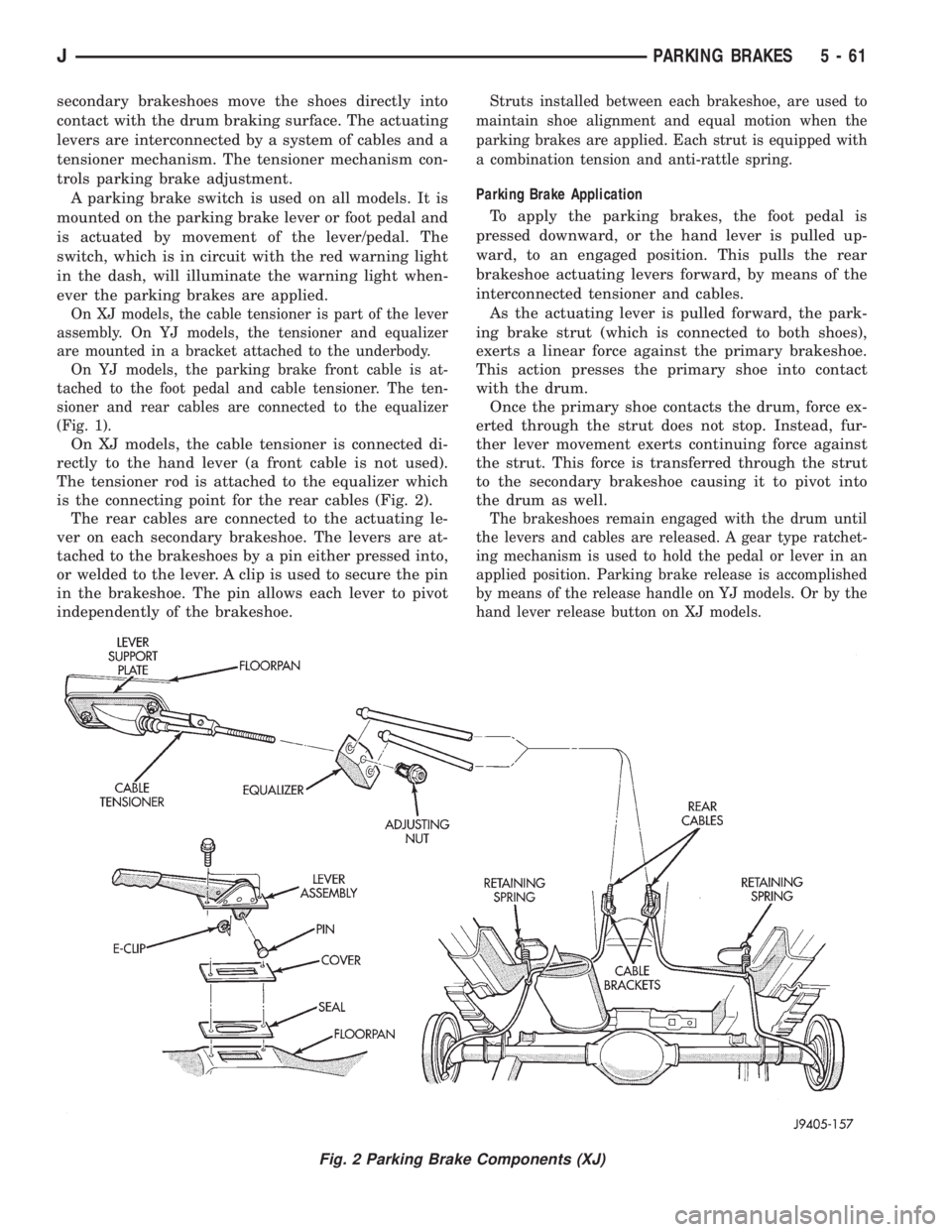
(Fig. 1).
On XJ models, the cable tensioner is connected di-
rectly to the hand lever (a front cable is not used).
The tensioner rod is attached to the equalizer which
is the connecting point for the rear cables (Fig. 2).
The rear cables are connected to the actuating le-
ver on each secondary brakeshoe. The levers are at-
tached to the brakeshoes by a pin either pressed into,
or welded to the lever. A clip is used to secure the pin
in the brakeshoe. The pin allows each lever to pivot
independently of the brakeshoe.
Struts installed between each brakeshoe, are used to
maintain shoe alignment and equal motion when the
parking brakes are applied. Each strut is equipped with
a combination tension and anti-rattle spring.
Parking Brake Application
To apply the parking brakes, the foot pedal is
pressed downward, or the hand lever is pulled up-
ward, to an engaged position. This pulls the rear
brakeshoe actuating levers forward, by means of the
interconnected tensioner and cables.
As the actuating lever is pulled forward, the park-
ing brake strut (which is connected to both shoes),
exerts a linear force against the primary brakeshoe.
This action presses the primary shoe into contact
with the drum.
Once the primary shoe contacts the drum, force ex-
erted through the strut does not stop. Instead, fur-
ther lever movement exerts continuing force against
the strut. This force is transferred through the strut
to the secondary brakeshoe causing it to pivot into
the drum as well.
The brakeshoes remain engaged with the drum until
the levers and cables are released. A gear type ratchet-
ing mechanism is used to hold the pedal or lever in an
applied position. Parking brake release is accomplished
by means of the release handle on YJ models. Or by the
hand lever release button on XJ models.
Fig. 2 Parking Brake Components (XJ)
JPARKING BRAKES 5 - 61
Page 216 of 2158
(8) Remove shift handle by pulling upward sharply
on handle. Then remove shift bezel (Fig. 7).
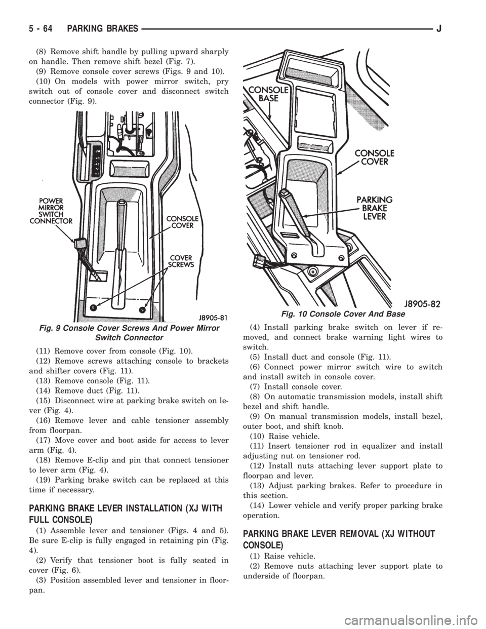
(9) Remove console cover screws (Figs. 9 and 10).
(10) On models with power mirror switch, pry
switch out of console cover and disconnect switch
connector (Fig. 9).
(11) Remove cover from console (Fig. 10).
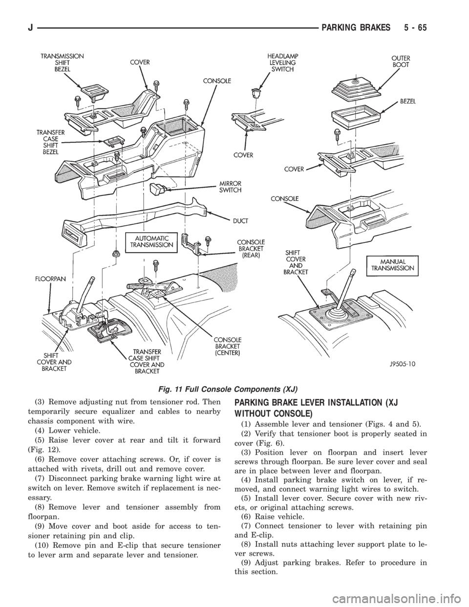
(12) Remove screws attaching console to brackets
and shifter covers (Fig. 11).
(13) Remove console (Fig. 11).
(14) Remove duct (Fig. 11).
(15) Disconnect wire at parking brake switch on le-
ver (Fig. 4).
(16) Remove lever and cable tensioner assembly
from floorpan.
(17) Move cover and boot aside for access to lever
arm (Fig. 4).
(18) Remove E-clip and pin that connect tensioner
to lever arm (Fig. 4).
(19) Parking brake switch can be replaced at this
time if necessary.
PARKING BRAKE LEVER INSTALLATION (XJ WITH
FULL CONSOLE)
(1) Assemble lever and tensioner (Figs. 4 and 5).
Be sure E-clip is fully engaged in retaining pin (Fig.
4).
(2) Verify that tensioner boot is fully seated in
cover (Fig. 6).
(3) Position assembled lever and tensioner in floor-
pan.(4) Install parking brake switch on lever if re-
moved, and connect brake warning light wires to
switch.
(5) Install duct and console (Fig. 11).
(6) Connect power mirror switch wire to switch
and install switch in console cover.
(7) Install console cover.
(8) On automatic transmission models, install shift
bezel and shift handle.
(9) On manual transmission models, install bezel,
outer boot, and shift knob.
(10) Raise vehicle.
(11) Insert tensioner rod in equalizer and install
adjusting nut on tensioner rod.
(12) Install nuts attaching lever support plate to
floorpan and lever.
(13) Adjust parking brakes. Refer to procedure in
this section.
(14) Lower vehicle and verify proper parking brake
operation.PARKING BRAKE LEVER REMOVAL (XJ WITHOUT
CONSOLE)
(1) Raise vehicle.
(2) Remove nuts attaching lever support plate to
underside of floorpan.
Fig. 9 Console Cover Screws And Power Mirror
Switch Connector
Fig. 10 Console Cover And Base
5 - 64 PARKING BRAKESJ
Page 217 of 2158
(3) Remove adjusting nut from tensioner rod. Then
temporarily secure equalizer and cables to nearby
chassis component with wire.
(4) Lower vehicle.
(5) Raise lever cover at rear and tilt it forward
(Fig. 12).
(6) Remove cover attaching screws. Or, if cover is
attached with rivets, drill out and remove cover.
(7) Disconnect parking brake warning light wire at
switch on lever. Remove switch if replacement is nec-
essary.
(8) Remove lever and tensioner assembly from
floorpan.
(9) Move cover and boot aside for access to ten-
sioner retaining pin and clip.
(10) Remove pin and E-clip that secure tensioner
to lever arm and separate lever and tensioner.PARKING BRAKE LEVER INSTALLATION (XJ
WITHOUT CONSOLE)
(1) Assemble lever and tensioner (Figs. 4 and 5).
(2) Verify that tensioner boot is properly seated in
cover (Fig. 6).
(3) Position lever on floorpan and insert lever
screws through floorpan. Be sure lever cover and seal
are in place between lever and floorpan.
(4) Install parking brake switch on lever, if re-
moved, and connect warning light wires to switch.
(5) Install lever cover. Secure cover with new riv-
ets, or original attaching screws.
(6) Raise vehicle.
(7) Connect tensioner to lever with retaining pin
and E-clip.
(8) Install nuts attaching lever support plate to le-
ver screws.
(9) Adjust parking brakes. Refer to procedure in
this section.
Fig. 11 Full Console Components (XJ)
JPARKING BRAKES 5 - 65
Page 218 of 2158
PARKING BRAKE CABLE TENSIONER
REPLACEMENT (XJ)
(1) Raise vehicle.
(2) Remove adjuster nut from tensioner rod. Secure
equalizer and cables to nearby chassis component
with wire.
(3) Remove nuts attaching lever assembly to sup-
port plate and floorpan.
(4) Lower vehicle.
(5) Remove console components and lever assembly
cover.
(6) Remove lever and tensioner assembly.
(7) Move cover and boot for access to tensioner re-
taining pin.
(8) Remove E-clip and pin that attach tensioner to
lever arm (Fig. 4).
(9) Remove tensioner from cover.
(10) Transfer boot to new tensioner if necessary.
(11) Attach tensioner to lever arm with pin and E-
clip.
(12) Verify that E-clip is fully engaged in pin (Fig.
4).
(13) Align cover and seal on lever flange.
(14) Verify that tensioner boot is seated in cover
(Fig. 6).
(15) Install assembled lever and tensioner in floor-
pan.
(16) Install necessary console components.
(17) Adjust parking brakes as described in this sec-
tion.
PARKING BRAKE PEDAL REMOVAL (YJ)
(1) Raise vehicle.
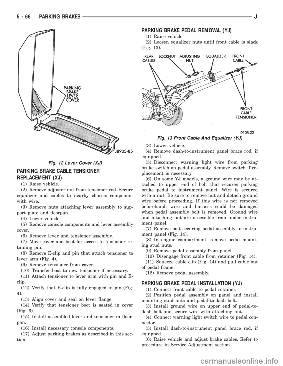
(2) Loosen equalizer nuts until front cable is slack
(Fig. 13).
(3) Lower vehicle.
(4) Remove dash-to-instrument panel brace rod, if
equipped.
(5) Disconnect warning light wire from parking
brake switch on pedal assembly. Remove switch if re-
placement is necessary.
(6) On some YJ models, a ground wire may be at-
tached to upper end of bolt that secures parking
brake pedal to instrument panel. Wire is secured
with a nut. Be sure to remove nut and detach ground
wire before proceeding. If this wire is not removed
beforehand, wire and harness could be damaged
when pedal assembly bolt is removed. Ground wire
and attaching nut are accessible from under instru-
ment panel.
(7) Remove bolt securing pedal assembly to instru-
ment panel (Fig. 14).
(8) In engine compartment, remove pedal mount-
ing stud nuts.
(9) Remove pedal assembly from panel.
(10) Disengage front cable from retainer (Fig. 14).
(11) Squeeze cable clip (Fig. 14) and pull cable out
of pedal frame.
(12) Remove pedal assembly.
PARKING BRAKE PEDAL INSTALLATION (YJ)
(1) Connect front cable to pedal retainer.
(2) Position pedal assembly on panel and install
mounting stud nuts and pedal-to-dash bolt.
(3) Install ground wire on upper end of pedal-to-
dash bolt and secure wire with attaching nut.
(4) Connect warning light switch wire to pedal con-
nector.
(5) Install dash-to-instrument panel brace rod, if
equipped.
(6) Raise vehicle and adjust brake cables. Refer to
procedure in Service Adjustment section.
Fig. 12 Lever Cover (XJ)
Fig. 13 Front Cable And Equalizer (YJ)
5 - 66 PARKING BRAKESJ
Page 244 of 2158
EXAMPLES:
²If the lamp (Figs. 5 or 6) flashes 1 time, pauses
and flashes 2 more times, a flashing Diagnostic Trou-
ble Code (DTC) number 12 is indicated. If this code is
observed, it is indicating that the battery has been
disconnected within the last 50 key-on cycles. It
could also indicate that battery voltage has been dis-
connected to the PCM. In either case, other DTC's
may have been erased.
²If the lamp flashes 1 time, pauses and flashes 7
more times, a flashing Diagnostic Trouble Code
(DTC) number 17 is indicated.
²If the lamp flashes 3 times, pauses and flashes 5
more times, a flashing Diagnostic Trouble Code
(DTC) number 35 is indicated.
After any stored DTC information has been ob-
served, the display will end with a flashing DTC
number 55. This will indicate the end of all stored in-
formation.
ERASING TROUBLE CODES
After the problem has been repaired, the DRB scan
tool must be used to erase a DTC. Refer to the ap-
propriate Powertrain Diagnostic Procedures service
manual for operation of the DRB scan tool.
DRB SCAN TOOL
For operation of the DRB scan tool, refer to the ap-
propriate Powertrain Diagnostic Procedures service
manual.
PRELIMINARY CHECKS
ENGINE COOLING SYSTEM OVERHEATING
Establish what driving conditions caused the com-
plaint. Abnormal loads on the cooling system such as
the following may be the cause.
1. PROLONGED IDLE, VERY HIGH AMBIENT
TEMPERATURE, SLIGHT TAIL WIND AT IDLE,
SLOW TRAFFIC, TRAFFIC JAMS, HIGH
SPEED, OR STEEP GRADES:
Driving techniques that avoid overheating are:
²Idle with A/C off when temperature gauge is at
end of normal range.
²Increasing engine speed for more air flow is recom-
mended.
2. TRAILER TOWING:
Consult Trailer Towing section of owners manual.
Do not exceed limits.
3. AIR CONDITIONING; ADD-ON OR AFTER
MARKET:
A maximum cooling package should have been or-
dered with vehicle if add-on or after market A/C is
installed. If not, maximum cooling system compo-
nents should be installed for model involved per
manufacturer's specifications.
4. RECENT SERVICE OR ACCIDENT REPAIR:
Determine if any recent service has been performed
on vehicle that may effect cooling system. This may
be:
²Engine adjustments (incorrect timing)
²Slipping engine accessory drive belt(s)
²Brakes (possibly dragging)
²Changed parts (incorrect water pump rotating in
wrong direction)
²Reconditioned radiator or cooling system refilling
(possibly under-filled or air trapped in system).
If investigation reveals none of the previous
items as a cause for an engine overheating com-
plaint, refer to following Cooling System Diag-
nosis charts.
These charts are to be used as a quick-reference
only. Refer to the group text for information.
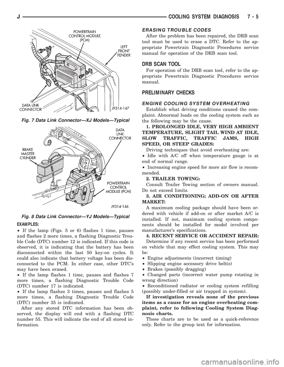
Fig. 7 Data Link ConnectorÐXJ ModelsÐTypical
Fig. 8 Data Link ConnectorÐYJ ModelsÐTypical
JCOOLING SYSTEM DIAGNOSIS 7 - 5
Page 334 of 2158

IGNITION SECONDARY CIRCUIT DIAGNOSIS
CHECKING FOR SPARK
CAUTION: When disconnecting a high voltage cable
from a spark plug or from the distributor cap, twist
the rubber boot slightly (1/2 turn) to break it loose
(Fig. 12). Grasp the boot (not the cable) and pull it
off with a steady, even force.
(1) Disconnect the ignition coil secondary cable
from center tower of the distributor cap. Hold the ca-
ble terminal approximately 12 mm (1/2 in.) from a
good engine ground (Fig. 13).
WARNING: BE VERY CAREFUL WHEN THE ENGINE
IS CRANKING. DO NOT PUT YOUR HANDS NEAR
THE PULLEYS, BELTS OR THE FAN. DO NOT WEAR
LOOSE FITTING CLOTHING.
(2) Rotate (crank) the engine with the starter mo-
tor and observe the cable terminal for a steady arc. If
steady arcing does not occur, inspect the secondary
coil cable. Refer to Spark Plug Cables in this group.
Also inspect the distributor cap and rotor for cracksor burn marks. Repair as necessary. If steady arcing
occurs, connect ignition coil cable to the distributor
cap.
(3) Remove a cable from one spark plug.
(4) Using insulated pliers, hold the cable terminal
approximately 12 mm (1/2 in.) from the engine cylin-
der head or block while rotating the engine with the
starter motor. Observe the spark plug cable terminal
for an arc. If steady arcing occurs, it can be expected
that the ignition secondary system is operating cor-
rectly.(note that if the ignition coil cable is re-
moved for this test, instead of a spark plug
cable, the spark intensity will be much higher.)
If steady arcing occurs at the spark plug cables, but
the engine will not start, connect the DRB scan tool.
Refer to the Powertrain Diagnostic Procedures ser-
vice manual.
FAILURE TO START TEST
To prevent unnecessary diagnostic time and wrong
test results, the previous Checking For Spark test
should be performed prior to this test.
WARNING: SET PARKING BRAKE OR BLOCK THE
DRIVE WHEELS BEFORE PROCEEDING WITH THIS
TEST.
(1) Unplug the ignition coil harness connector at
the coil (Fig. 14).
(2) Connect a set of small jumper wires (18 gauge
or smaller) between the disconnected harness termi-
nals and the ignition coil terminals. To determine po-
larity at connector and coil, refer to the Wiring
Diagrams section.
(3) Attach one lead of a voltmeter to the positive
(12 volt) jumper wire. Attach the negative side of
voltmeter to a good ground. Determine that sufficient
battery voltage (12.4 volts) is present for the starting
and ignition systems.
Fig. 12 Cable Removal
Fig. 13 Checking for SparkÐTypical
Fig. 14 Coil Harness ConnectorÐTypical (4.0L
Shown)
8D - 10 IGNITION SYSTEMSJ
Page 359 of 2158

TACHOMETER
The tachometer gives an indication of engine speed
in Revolutions-Per-Minute (RPM). With the engine
running, the tachometer receives an engine speed
pulse signal from the Powertrain Control Module
(PCM). An electronic integrated circuit contained
within the tachometer reads and analyzes the pulse
signal. It then adjusts the ground path resistance of
one electromagnet in the gauge to control needle
movement. Frequency values for the pulse signal are
shown in a chart in Specifications.
TRIP ODOMETER
The trip odometer is driven by the same electronic
integrated circuit as the speedometer/odometer. How-
ever, by depressing the trip odometer reset knob on
the face of the speedometer, the trip odometer can be
reset to zero. The trip odometer is serviced only as a
part of the speedometer/odometer gauge assembly.
VOLTMETER
The voltmeter is connected in parallel with the bat-
tery. With the ignition switch ON, the voltmeter in-
dicates battery or generator output voltage,
whichever is greater.
INDICATOR LAMPS
Indicator lamps are located in two areas within the
cluster. Each of these areas is served by a separate
printed circuit and cluster connector. Those lamps in
the gauge area of the cluster share the gauge area
printed circuit and cluster connector A. Those lamps
in the tell-tale area of the cluster use the tell-tale
printed circuit and cluster (tell-tale) connector B.
Up to ten indicator lamps can be found in the tell-
tale area of the cluster. These lamps are arranged in
five stacked rows with two lamps in each row, located
to the driver's side of the main cluster.
ANTI-LOCK BRAKE SYSTEM LAMP
The Anti-Lock Brake System (ABS) lamp is
switched to ground by the ABS module. The module
lights the lamp when the ignition switch is turned to
the START position as a bulb test. The lamp will
stay on for 3 to 5 seconds after vehicle start-up to in-
dicate a system self-test is in process. If the lamp re-
mains on after start-up, or comes on and stays on
while driving, it may indicate that the ABS module
has detected a system malfunction or that the system
has become inoperative. Refer to Group 5 - Brakes
for more information.
BRAKE WARNING LAMP
The brake warning lamp warns the driver that the
parking brake is applied or that the pressures in the
two halves of the split brake hydraulic system are
unequal. With the ignition switch turned ON, batteryvoltage is supplied to one side of the indicator bulb. A
ground path for the bulb is provided by 3 switches.
The bulb will light when:
²the brake warning switch is closed (indicating un-
equal brake system hydraulic pressures possibly due
to brake fluid leakage)
²the ignition switch is in the START position (bulb
test)
²the parking brake switch is closed (parking brake
is applied).
Refer to Group 5 - Brakes for more information.
COOLANT TEMPERATURE WARNING LAMP
The coolant temperature warning lamp lights
whenever engine coolant temperature is too high.
Battery voltage is supplied to one side of the indica-
tor bulb when the ignition switch is turned ON. The
normally open coolant temperature switch is con-
nected to the other side of the bulb. When coolant
temperature is too high, the switch closes. This pro-
vides a ground path for the indicator bulb, which
causes it to light. The lamp is also grounded and
should light with the ignition switch in the START
position as a bulb test.
FOUR-WHEEL DRIVE INDICATOR LAMPS
PART TIME
On vehicles with Command-Trac 4WD, the Part
Time lamp lights when the transfer case is engaged
in the 4H or 4L position. On vehicles with Selec-Trac
4WD, the Part Time lamp lights when the transfer
case is engaged in the4X4PARTTIME or 4 LO po-
sition. Voltage is supplied to one side of the indicator
bulb. A switch in the transfer case is connected to the
other side of the indicator bulb. When the switch is
closed, a path to ground is provided and the indicator
bulb lights.
FULL TIME
The Full Time lamp is only operational on vehicles
equipped with Selec-Trac 4WD. The Full Time lamp
lights when the transfer case is engaged in the4X4
Full Time position. Voltage is supplied to one side of
the indicator bulb. A switch in the transfer case is
connected to the other side of the indicator bulb.
When the switch is closed, a path to ground is pro-
vided and the indicator bulb lights.
GENERATOR WARNING LAMP
The generator warning lamp lights with the igni-
tion switch turned to ON, but should go out when-
ever the engine is running. If the lamp comes on and
stays on while the engine is running, it indicates
that a charging system malfunction exists. One side
of the bulb is connected to ignition-switched battery
feed. The other side of the bulb is switched to ground
by the Powertrain Control Module (PCM).
JINSTRUMENT PANEL AND GAUGESÐXJ 8E - 3