1995 JEEP YJ body components
[x] Cancel search: body componentsPage 1392 of 2158
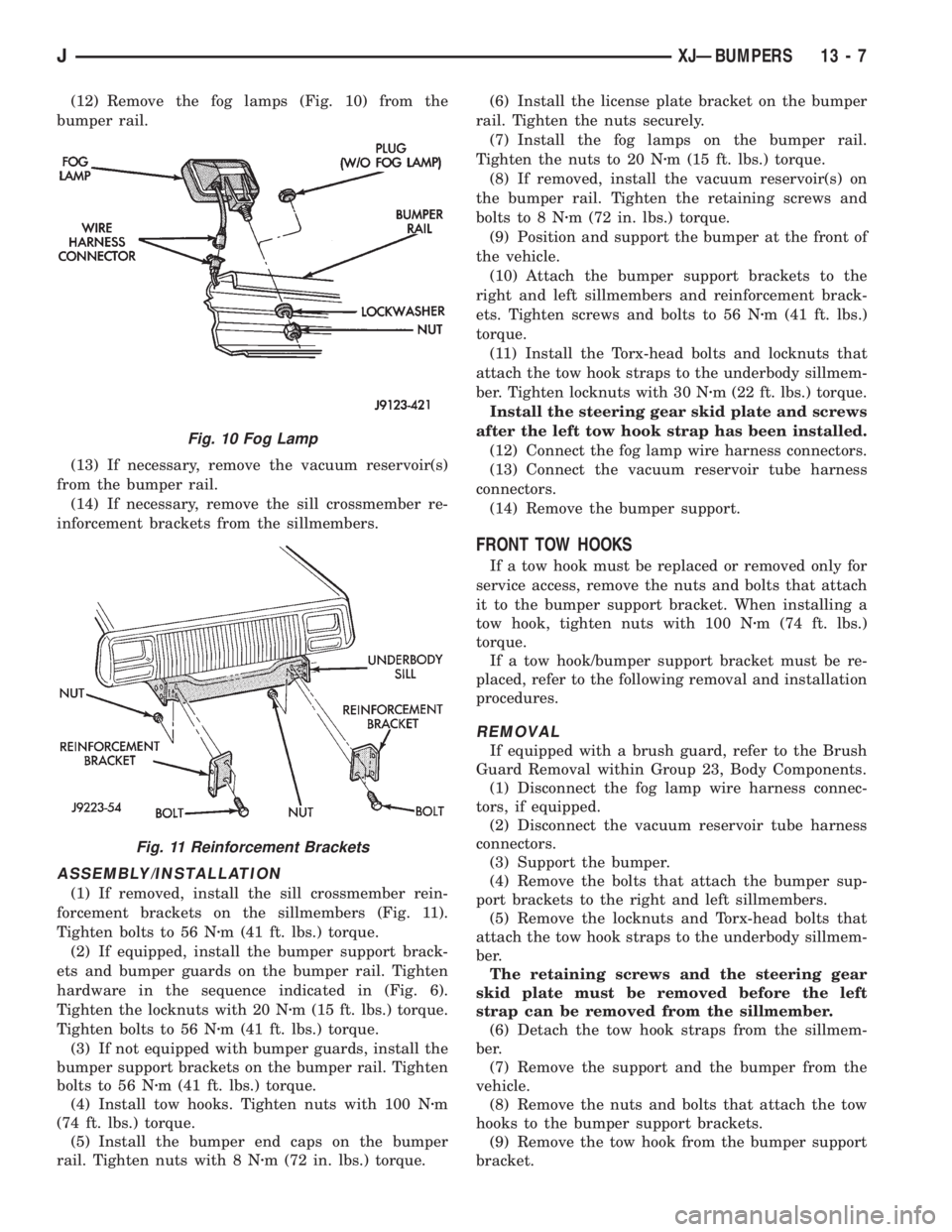
(12) Remove the fog lamps (Fig. 10) from the
bumper rail.
(13) If necessary, remove the vacuum reservoir(s)
from the bumper rail.
(14) If necessary, remove the sill crossmember re-
inforcement brackets from the sillmembers.
ASSEMBLY/INSTALLATION
(1) If removed, install the sill crossmember rein-
forcement brackets on the sillmembers (Fig. 11).
Tighten bolts to 56 Nzm (41 ft. lbs.) torque.
(2) If equipped, install the bumper support brack-
ets and bumper guards on the bumper rail. Tighten
hardware in the sequence indicated in (Fig. 6).
Tighten the locknuts with 20 Nzm (15 ft. lbs.) torque.
Tighten bolts to 56 Nzm (41 ft. lbs.) torque.
(3) If not equipped with bumper guards, install the
bumper support brackets on the bumper rail. Tighten
bolts to 56 Nzm (41 ft. lbs.) torque.
(4) Install tow hooks. Tighten nuts with 100 Nzm
(74 ft. lbs.) torque.
(5) Install the bumper end caps on the bumper
rail. Tighten nuts with 8 Nzm (72 in. lbs.) torque.(6) Install the license plate bracket on the bumper
rail. Tighten the nuts securely.
(7) Install the fog lamps on the bumper rail.
Tighten the nuts to 20 Nzm (15 ft. lbs.) torque.
(8) If removed, install the vacuum reservoir(s) on
the bumper rail. Tighten the retaining screws and
bolts to 8 Nzm (72 in. lbs.) torque.
(9) Position and support the bumper at the front of
the vehicle.
(10) Attach the bumper support brackets to the
right and left sillmembers and reinforcement brack-
ets. Tighten screws and bolts to 56 Nzm (41 ft. lbs.)
torque.
(11) Install the Torx-head bolts and locknuts that
attach the tow hook straps to the underbody sillmem-
ber. Tighten locknuts with 30 Nzm (22 ft. lbs.) torque.
Install the steering gear skid plate and screws
after the left tow hook strap has been installed.
(12) Connect the fog lamp wire harness connectors.
(13) Connect the vacuum reservoir tube harness
connectors.
(14) Remove the bumper support.
FRONT TOW HOOKS
If a tow hook must be replaced or removed only for
service access, remove the nuts and bolts that attach
it to the bumper support bracket. When installing a
tow hook, tighten nuts with 100 Nzm (74 ft. lbs.)
torque.
If a tow hook/bumper support bracket must be re-
placed, refer to the following removal and installation
procedures.
REMOVAL
If equipped with a brush guard, refer to the Brush
Guard Removal within Group 23, Body Components.
(1) Disconnect the fog lamp wire harness connec-
tors, if equipped.
(2) Disconnect the vacuum reservoir tube harness
connectors.
(3) Support the bumper.
(4) Remove the bolts that attach the bumper sup-
port brackets to the right and left sillmembers.
(5) Remove the locknuts and Torx-head bolts that
attach the tow hook straps to the underbody sillmem-
ber.
The retaining screws and the steering gear
skid plate must be removed before the left
strap can be removed from the sillmember.
(6) Detach the tow hook straps from the sillmem-
ber.
(7) Remove the support and the bumper from the
vehicle.
(8) Remove the nuts and bolts that attach the tow
hooks to the bumper support brackets.
(9) Remove the tow hook from the bumper support
bracket.
Fig. 10 Fog Lamp
Fig. 11 Reinforcement Brackets
JXJÐBUMPERS 13 - 7
Page 1393 of 2158
(10) Remove the support bracket from the bumper
rail.
INSTALLATION
(1) Install the bumper guard and bumper support
bracket on the bumper rail. Tighten the retaining
hardware in the sequence indicated in Figure 7.
Tighten locknuts to 20 Nzm (15 ft. lbs.) torque.
Tighten bolts to 56 Nzm (41 ft. lbs.) torque.
(2) If not equipped with bumper guards, install the
bumper support bracket on the bumper rail. Tighten
bolts to 56 Nzm (41 ft. lbs.) torque.
(3) Position the tow hook at the support bracket.
Install the bolts and nuts that attach tow hook to the
bumper support bracket. Tighten nuts to 100 Nzm (74
ft. lbs.) torque.
(4) Position and support the bumper at the front of
the vehicle.
(5) Attach the bumper support brackets to the
right and left sillmembers and reinforcement brack-
ets. Tighten screws and bolts to 56 Nzm (41 ft. lbs.)
torque.
(6) Install the Torx-head bolts and locknuts that
attach the tow hook straps to the underbody sillmem-
ber. Tighten locknuts to 30 Nzm (22 ft. lbs.) torque.
Install the steering gear skid plate and screws
after the left tow hook strap has been installed.
(7) Connect the fog lamp wire harness connectors.
Connect the vacuum reservoir tube harness connec-
tors.
(8) Remove the bumper support.
REAR BUMPER
REMOVAL
(1) For vehicles equipped with a trailer hitch, re-
move the hitch before removing the bumper. If neces-
sary, refer to the removal procedure within Group 23,
Body Components.
(2) Raise and support the rear of the vehicle.
(3) Support the bumper.
(4) Remove the bolts that attach the bumper sup-
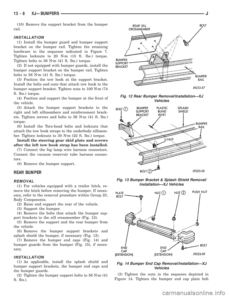
port brackets to the sill crossmember (Fig. 12).
(5) Remove the support and the rear bumper from
the vehicle.
(6) Remove the bumper support brackets and
splash shield the bumper, if necessary (Fig. 13).
(7) Remove the bumper end caps (Fig. 14) and
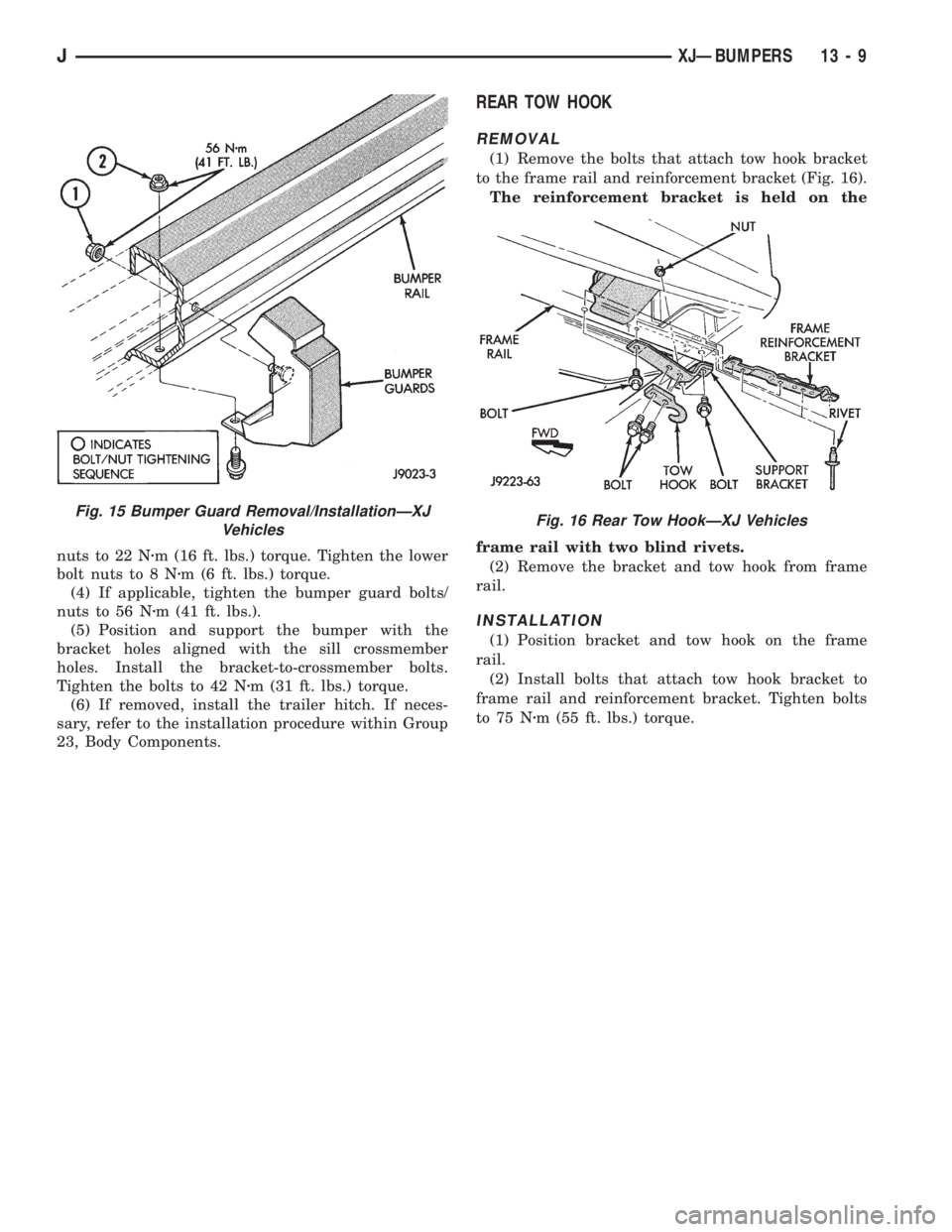
bumper guards from the bumper (Fig. 15), if neces-
sary.
INSTALLATION
(1) As applicable, install the splash shield and
bumper support brackets, the bumper end caps and
the bumper guards.
(2) Tighten the bumper support bolts to 56 Nzm (41
ft. lbs.).(3) Tighten the nuts in the sequence depicted in
Figure 14. Tighten the bumper end cap plate bolt
Fig. 12 Rear Bumper Removal/InstallationÐXJ
Vehicles
Fig. 13 Bumper Bracket & Splash Shield Removal/
InstallationÐXJ Vehicles
Fig. 14 Bumper End Cap Removal/InstallationÐXJ
Vehicles
13 - 8 XJÐBUMPERSJ
Page 1394 of 2158
nuts to 22 Nzm (16 ft. lbs.) torque. Tighten the lower
bolt nuts to 8 Nzm (6 ft. lbs.) torque.
(4) If applicable, tighten the bumper guard bolts/
nuts to 56 Nzm (41 ft. lbs.).
(5) Position and support the bumper with the
bracket holes aligned with the sill crossmember
holes. Install the bracket-to-crossmember bolts.
Tighten the bolts to 42 Nzm (31 ft. lbs.) torque.
(6) If removed, install the trailer hitch. If neces-
sary, refer to the installation procedure within Group
23, Body Components.
REAR TOW HOOK
REMOVAL
(1) Remove the bolts that attach tow hook bracket
to the frame rail and reinforcement bracket (Fig. 16).
The reinforcement bracket is held on the
frame rail with two blind rivets.
(2) Remove the bracket and tow hook from frame
rail.
INSTALLATION
(1) Position bracket and tow hook on the frame
rail.
(2) Install bolts that attach tow hook bracket to
frame rail and reinforcement bracket. Tighten bolts
to 75 Nzm (55 ft. lbs.) torque.
Fig. 15 Bumper Guard Removal/InstallationÐXJ
VehiclesFig. 16 Rear Tow HookÐXJ Vehicles
JXJÐBUMPERS 13 - 9
Page 1395 of 2158
FRAME
INDEX
page page
Frame Dimensions........................ 13
Frame Repairs........................... 13
Frame Straightening....................... 13
Fuel Tank Skid Plate....................... 15
General Information....................... 10Generator Splash Shield.................... 13
Safety Precautions and Warnings............. 10
Tow Hooks.............................. 13
Transfer Case Skid Plate.................... 15
SAFETY PRECAUTIONS AND WARNINGS
WARNING: USE EYE PROTECTION WHEN GRIND-
ING OR WELDING METAL, SERIOUS EYE INJURY
CAN RESULT.
BEFORE PROCEEDING WITH FRAME REPAIR IN-
VOLVING GRINDING OR WELDING, VERIFY THAT
VEHICLE FUEL SYSTEM IS NOT LEAKING OR IN
CONTACT WITH REPAIR AREA, PERSONAL INJURY
CAN RESULT.
DO NOT ALLOW OPEN FLAME TO CONTACT
PLASTIC BODY PANELS. FIRE OR EXPLOSION CAN
RESULT.
WHEN WELDED FRAME COMPONENTS ARE RE-
PLACED, 100% PENETRATION WELD MUST BE
ACHIEVED DURING INSTALLATION. IF NOT, DAN-
GEROUS OPERATING CONDITIONS CAN RESULT.
STAND CLEAR OF CABLES OR CHAINS ON
PULLING EQUIPMENT DURING FRAME STRAIGHT-
ENING OPERATIONS, PERSONAL INJURY CAN RE-
SULT.
DO NOT VENTURE UNDER A HOISTED VEHICLE
THAT IS NOT SUPPORTED ON SAFETY STANDS,
PERSONAL INJURY CAN RESULT.
CAUTION: Do not reuse damaged fasteners, quality
of repair would be suspect.
Do not drill holes in top or bottom frame rail
flanges, frame rail failure can result.
Do Not use softer than Grade 3 bolts to replace
production fasteners, loosening or failure can re-
sult.When using heat to straighten frame components
do not exceed 566ÉC (1050ÉF), metal fatigue can re-
sult.
Welding the joints around riveted cross members
and frame side rails can weaken frame
GENERAL INFORMATION
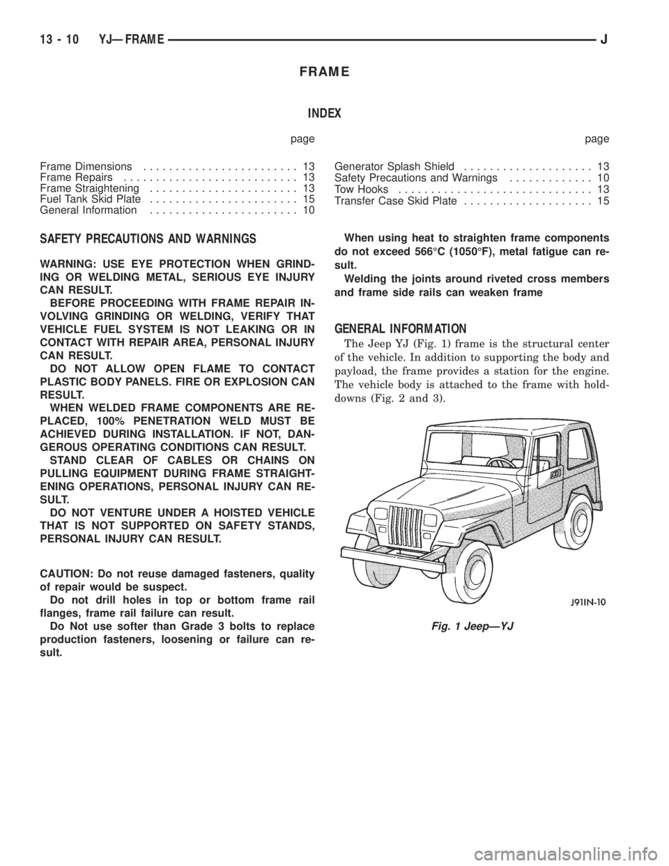
The Jeep YJ (Fig. 1) frame is the structural center
of the vehicle. In addition to supporting the body and
payload, the frame provides a station for the engine.
The vehicle body is attached to the frame with hold-
downs (Fig. 2 and 3).
Fig. 1 JeepÐYJ
13 - 10 YJÐFRAMEJ
Page 1412 of 2158
WARNING: THE FUEL SYSTEM IS UNDER A CON-
STANT PRESSURE (EVEN WITH THE ENGINE OFF).
BEFORE SERVICING ANY FUEL SYSTEM HOSES,
FITTINGS OR LINES, THE FUEL SYSTEM PRES-
SURE MUST BE RELEASED. REFER TO THE FUEL
PRESSURE RELEASE PROCEDURE IN THIS
GROUP.
Inspect all hose connections such as clamps, cou-
plings and fittings to make sure they are secure and
leaks are not present. The component should be re-
placed immediately if there is any evidence of degra-
dation that could result in failure.
Never attempt to repair a plastic fuel line/tube. Re-
place as necessary.
Avoid contact of any fuel tubes/hoses with other ve-
hicle components that could cause abrasions or scuff-
ing. Be sure that the plastic fuel lines/tubes are
properly routed to prevent pinching and to avoid heat
sources.
The lines/tubes/hoses used on fuel injected vehicles
are of a special construction. This is due to the
higher fuel pressures and the possibility of contami-
nated fuel in this system. If it is necessary to replace
these lines/tubes/hoses, only those marked EFM/EFI
may be used.
The hose clamps used to secure rubber hoses on
fuel injected vehicles are of a special rolled edge con-
struction. This construction is used to prevent the
edge of the clamp from cutting into the hose. Only
these rolled edge type clamps may be used in this
system. All other types of clamps may cut into the
hoses and cause high-pressure fuel leaks.
Use new original equipment type hose clamps.
Tighten hose clamps to 1 Nzm (15 in. lbs.) torque.
QUICK-CONNECT FITTINGS
Also refer to the previous Fuel Tubes/Lines/Hoses
and Clamps section.
Different types of quick-connect fittings are used to
attach various fuel system components. These are: a
single-tab type, a two-tab type or a plastic retainer
ring type.
SINGLE-TAB TYPE
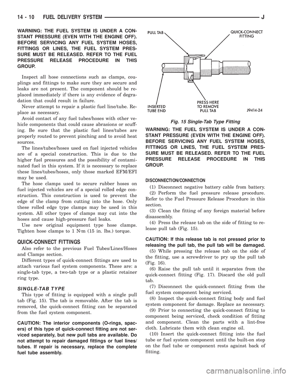
This type of fitting is equipped with a single pull
tab (Fig. 15). The tab is removable. After the tab is
removed, the quick-connect fitting can be separated
from the fuel system component.
CAUTION: The interior components (O-rings, spac-
ers) of this type of quick-connect fitting are not ser-
viced separately, but new pull tabs are available. Do
not attempt to repair damaged fittings or fuel lines/
tubes. If repair is necessary, replace the complete
fuel tube assembly.WARNING: THE FUEL SYSTEM IS UNDER A CON-
STANT PRESSURE (EVEN WITH THE ENGINE OFF).
BEFORE SERVICING ANY FUEL SYSTEM HOSES,
FITTINGS OR LINES, THE FUEL SYSTEM PRES-
SURE MUST BE RELEASED. REFER TO THE FUEL
PRESSURE RELEASE PROCEDURE IN THIS
GROUP.
DISCONNECTION/CONNECTION
(1) Disconnect negative battery cable from battery.
(2) Perform the fuel pressure release procedure.
Refer to the Fuel Pressure Release Procedure in this
section.
(3) Clean the fitting of any foreign material before
disassembly.
(4) Press the release tab on the side of fitting to re-
lease pull tab (Fig. 15).
CAUTION: If this release tab is not pressed prior to
releasing the pull tab, the pull tab will be damaged.
(5) While pressing the release tab on the side of
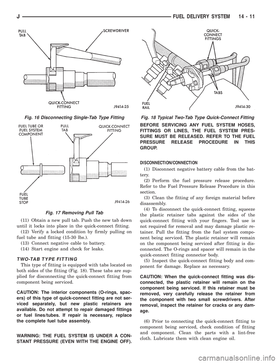
the fitting, use a screwdriver to pry up the pull tab
(Fig. 16).
(6) Raise the pull tab until it separates from the
quick-connect fitting (Fig. 17). Discard the old pull
tab.
(7) Disconnect the quick-connect fitting from the
fuel system component being serviced.
(8) Inspect the quick-connect fitting body and fuel
system component for damage. Replace as necessary.
(9) Prior to connecting the quick-connect fitting to
component being serviced, check condition of fitting
and component. Clean the parts with a lint-free
cloth. Lubricate them with clean engine oil.
(10) Insert the quick-connect fitting into the fuel
tube or fuel system component until the built-on stop
on the fuel tube or component rests against back of
fitting.
Fig. 15 Single-Tab Type Fitting
14 - 10 FUEL DELIVERY SYSTEMJ
Page 1413 of 2158
(11) Obtain a new pull tab. Push the new tab down
until it locks into place in the quick-connect fitting.
(12) Verify a locked condition by firmly pulling on
fuel tube and fitting (15-30 lbs.).
(13) Connect negative cable to battery.
(14) Start engine and check for leaks.
TWO-TAB TYPE FITTING
This type of fitting is equipped with tabs located on
both sides of the fitting (Fig. 18). These tabs are sup-
plied for disconnecting the quick-connect fitting from
component being serviced.
CAUTION: The interior components (O-rings, spac-
ers) of this type of quick-connect fitting are not ser-
viced separately, but new plastic retainers are
available. Do not attempt to repair damaged fittings
or fuel lines/tubes. If repair is necessary, replace
the complete fuel tube assembly.
WARNING: THE FUEL SYSTEM IS UNDER A CON-
STANT PRESSURE (EVEN WITH THE ENGINE OFF).BEFORE SERVICING ANY FUEL SYSTEM HOSES,
FITTINGS OR LINES, THE FUEL SYSTEM PRES-
SURE MUST BE RELEASED. REFER TO THE FUEL
PRESSURE RELEASE PROCEDURE IN THIS
GROUP.
DISCONNECTION/CONNECTION
(1) Disconnect negative battery cable from the bat-
tery.
(2) Perform the fuel pressure release procedure.
Refer to the Fuel Pressure Release Procedure in this
section.
(3) Clean the fitting of any foreign material before
disassembly.
(4) To disconnect the quick-connect fitting, squeeze
the plastic retainer tabs against the sides of the
quick-connect fitting with your fingers. Tool use is
not required for removal and may damage plastic re-
tainer. Pull the fitting from the fuel system compo-
nent being serviced. The plastic retainer will remain
on the component being serviced after fitting is dis-
connected. The O-rings and spacer will remain in the
quick-connect fitting connector body.
(5) Inspect the quick-connect fitting body and com-
ponent for damage. Replace as necessary.
CAUTION: When the quick-connect fitting was dis-
connected, the plastic retainer will remain on the
component being serviced. If this retainer must be
removed, very carefully release the retainer from
the component with two small screwdrivers. After
removal, inspect the retainer for cracks or any dam-
age.
(6) Prior to connecting the quick-connect fitting to
component being serviced, check condition of fitting
and component. Clean the parts with a lint-free
cloth. Lubricate them with clean engine oil.
Fig. 16 Disconnecting Single-Tab Type Fitting
Fig. 17 Removing Pull Tab
Fig. 18 Typical Two-Tab Type Quick-Connect Fitting
JFUEL DELIVERY SYSTEM 14 - 11
Page 1414 of 2158
(7) Insert the quick-connect fitting to the compo-
nent being serviced and into the plastic retainer.
When a connection is made, a click will be heard.
(8) Verify a locked condition by firmly pulling on
fuel tube and fitting (15-30 lbs.).
(9) Connect negative cable to battery.
(10) Start engine and check for leaks.
PLASTIC RETAINER RING TYPE FITTING
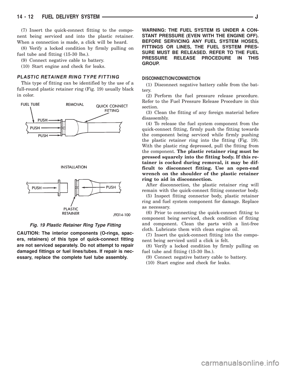
This type of fitting can be identified by the use of a
full-round plastic retainer ring (Fig. 19) usually black
in color.
CAUTION: The interior components (O-rings, spac-
ers, retainers) of this type of quick-connect fitting
are not serviced separately. Do not attempt to repair
damaged fittings or fuel lines/tubes. If repair is nec-
essary, replace the complete fuel tube assembly.WARNING: THE FUEL SYSTEM IS UNDER A CON-
STANT PRESSURE (EVEN WITH THE ENGINE OFF).
BEFORE SERVICING ANY FUEL SYSTEM HOSES,
FITTINGS OR LINES, THE FUEL SYSTEM PRES-
SURE MUST BE RELEASED. REFER TO THE FUEL
PRESSURE RELEASE PROCEDURE IN THIS
GROUP.
DISCONNECTION/CONNECTION
(1) Disconnect negative battery cable from the bat-
tery.
(2) Perform the fuel pressure release procedure.
Refer to the Fuel Pressure Release Procedure in this
section.
(3) Clean the fitting of any foreign material before
disassembly.
(4) To release the fuel system component from the
quick-connect fitting, firmly push the fitting towards
the component being serviced while firmly pushing
the plastic retainer ring into the fitting (Fig. 19).
With the plastic ring depressed, pull the fitting from
the component.The plastic retainer ring must be
pressed squarely into the fitting body. If this re-
tainer is cocked during removal, it may be dif-
ficult to disconnect fitting. Use an open-end
wrench on the shoulder of the plastic retainer
ring to aid in disconnection.
After disconnection, the plastic retainer ring will
remain with the quick-connect fitting connector body.
(5) Inspect fitting connector body, plastic retainer
ring and fuel system component for damage. Replace
as necessary.
(6) Prior to connecting the quick-connect fitting to
component being serviced, check condition of fitting
and component. Clean the parts with a lint-free
cloth. Lubricate them with clean engine oil.
(7) Insert the quick-connect fitting into the compo-
nent being serviced until a click is felt.
(8) Verify a locked condition by firmly pulling on
fuel tube and fitting (15-30 lbs.).
(9) Connect negative battery cable to battery.
(10) Start engine and check for leaks.
Fig. 19 Plastic Retainer Ring Type Fitting
14 - 12 FUEL DELIVERY SYSTEMJ
Page 1451 of 2158
IDLE AIR CONTROL MOTOR TEST
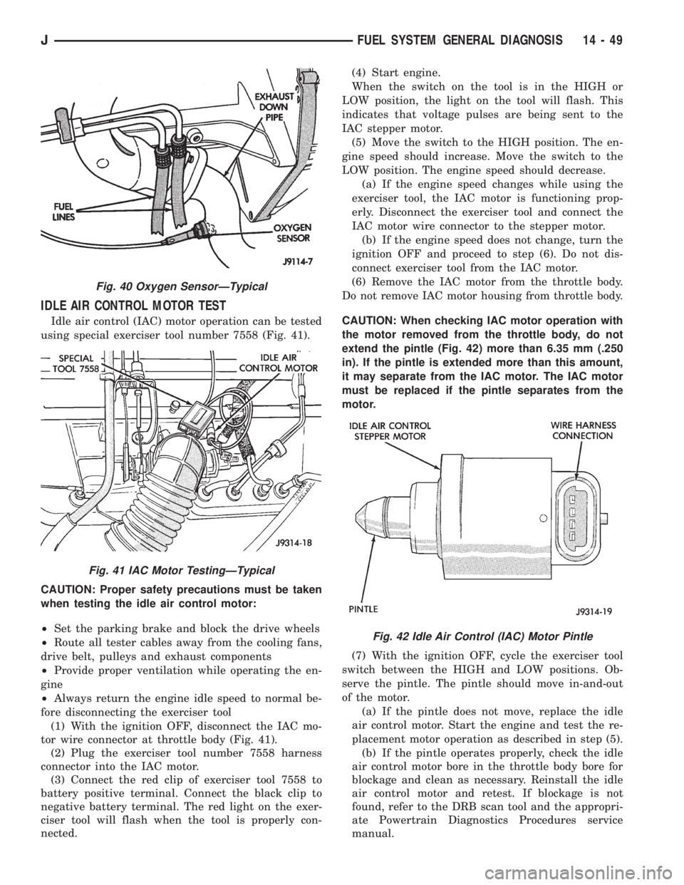
Idle air control (IAC) motor operation can be tested
using special exerciser tool number 7558 (Fig. 41).
CAUTION: Proper safety precautions must be taken
when testing the idle air control motor:
²Set the parking brake and block the drive wheels
²Route all tester cables away from the cooling fans,
drive belt, pulleys and exhaust components
²Provide proper ventilation while operating the en-
gine
²Always return the engine idle speed to normal be-
fore disconnecting the exerciser tool
(1) With the ignition OFF, disconnect the IAC mo-
tor wire connector at throttle body (Fig. 41).
(2) Plug the exerciser tool number 7558 harness
connector into the IAC motor.
(3) Connect the red clip of exerciser tool 7558 to
battery positive terminal. Connect the black clip to
negative battery terminal. The red light on the exer-
ciser tool will flash when the tool is properly con-
nected.(4) Start engine.
When the switch on the tool is in the HIGH or
LOW position, the light on the tool will flash. This
indicates that voltage pulses are being sent to the
IAC stepper motor.
(5) Move the switch to the HIGH position. The en-
gine speed should increase. Move the switch to the
LOW position. The engine speed should decrease.
(a) If the engine speed changes while using the
exerciser tool, the IAC motor is functioning prop-
erly. Disconnect the exerciser tool and connect the
IAC motor wire connector to the stepper motor.
(b) If the engine speed does not change, turn the
ignition OFF and proceed to step (6). Do not dis-
connect exerciser tool from the IAC motor.
(6) Remove the IAC motor from the throttle body.
Do not remove IAC motor housing from throttle body.
CAUTION: When checking IAC motor operation with
the motor removed from the throttle body, do not
extend the pintle (Fig. 42) more than 6.35 mm (.250
in). If the pintle is extended more than this amount,
it may separate from the IAC motor. The IAC motor
must be replaced if the pintle separates from the
motor.
(7) With the ignition OFF, cycle the exerciser tool
switch between the HIGH and LOW positions. Ob-
serve the pintle. The pintle should move in-and-out
of the motor.
(a) If the pintle does not move, replace the idle
air control motor. Start the engine and test the re-
placement motor operation as described in step (5).
(b) If the pintle operates properly, check the idle
air control motor bore in the throttle body bore for
blockage and clean as necessary. Reinstall the idle
air control motor and retest. If blockage is not
found, refer to the DRB scan tool and the appropri-
ate Powertrain Diagnostics Procedures service
manual.
Fig. 40 Oxygen SensorÐTypical
Fig. 41 IAC Motor TestingÐTypical
Fig. 42 Idle Air Control (IAC) Motor Pintle
JFUEL SYSTEM GENERAL DIAGNOSIS 14 - 49