1995 JEEP YJ body components
[x] Cancel search: body componentsPage 1303 of 2158
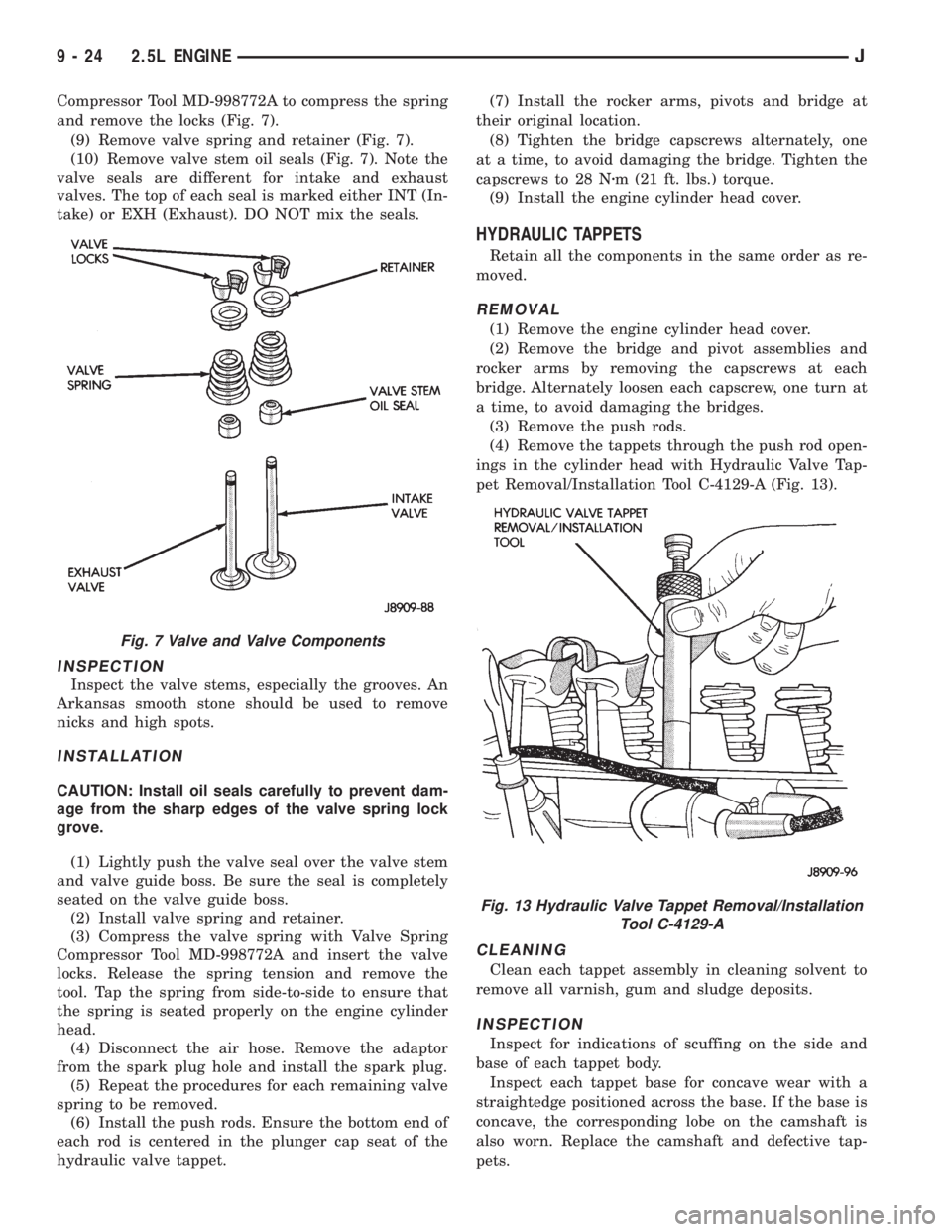
Compressor Tool MD-998772A to compress the spring
and remove the locks (Fig. 7).
(9) Remove valve spring and retainer (Fig. 7).
(10) Remove valve stem oil seals (Fig. 7). Note the
valve seals are different for intake and exhaust
valves. The top of each seal is marked either INT (In-
take) or EXH (Exhaust). DO NOT mix the seals.
INSPECTION
Inspect the valve stems, especially the grooves. An
Arkansas smooth stone should be used to remove
nicks and high spots.
INSTALLATION
CAUTION: Install oil seals carefully to prevent dam-
age from the sharp edges of the valve spring lock
grove.
(1) Lightly push the valve seal over the valve stem
and valve guide boss. Be sure the seal is completely
seated on the valve guide boss.
(2) Install valve spring and retainer.
(3) Compress the valve spring with Valve Spring
Compressor Tool MD-998772A and insert the valve
locks. Release the spring tension and remove the
tool. Tap the spring from side-to-side to ensure that
the spring is seated properly on the engine cylinder
head.
(4) Disconnect the air hose. Remove the adaptor
from the spark plug hole and install the spark plug.
(5) Repeat the procedures for each remaining valve
spring to be removed.
(6) Install the push rods. Ensure the bottom end of
each rod is centered in the plunger cap seat of the
hydraulic valve tappet.(7) Install the rocker arms, pivots and bridge at
their original location.
(8) Tighten the bridge capscrews alternately, one
at a time, to avoid damaging the bridge. Tighten the
capscrews to 28 Nzm (21 ft. lbs.) torque.
(9) Install the engine cylinder head cover.
HYDRAULIC TAPPETS
Retain all the components in the same order as re-
moved.
REMOVAL
(1) Remove the engine cylinder head cover.
(2) Remove the bridge and pivot assemblies and
rocker arms by removing the capscrews at each
bridge. Alternately loosen each capscrew, one turn at
a time, to avoid damaging the bridges.
(3) Remove the push rods.
(4) Remove the tappets through the push rod open-
ings in the cylinder head with Hydraulic Valve Tap-
pet Removal/Installation Tool C-4129-A (Fig. 13).
CLEANING
Clean each tappet assembly in cleaning solvent to
remove all varnish, gum and sludge deposits.
INSPECTION
Inspect for indications of scuffing on the side and
base of each tappet body.
Inspect each tappet base for concave wear with a
straightedge positioned across the base. If the base is
concave, the corresponding lobe on the camshaft is
also worn. Replace the camshaft and defective tap-
pets.
Fig. 7 Valve and Valve Components
Fig. 13 Hydraulic Valve Tappet Removal/Installation
Tool C-4129-A
9 - 24 2.5L ENGINEJ
Page 1316 of 2158
LUBRICATION SYSTEM
A gearÐtype positive displacement pump is
mounted at the underside of the block opposite the
No. 4 main bearing. The pump draws oil through the
screen and inlet tube from the sump at the rear of
the oil pan. The oil is driven between the drive and
idler gears and pump body, then forced through the
outlet to the block. An oil gallery in the block chan-
nels the oil to the inlet side of the full flow oil filter.
After passing through the filter element, the oil
passes from the center outlet of the filter through an
oil gallery that channels the oil up to the main gal-
lery which extends the entire length of the block.
Galleries extend downward from the main oil gal-
lery to the upper shell of each main bearing. The
crankshaft is drilled internally to pass oil from the
main bearing journals (except number 4 main bear-
ing journal) to the connecting rod journals. Each con-
necting rod bearing cap has a small squirt hole, oilpasses through the squirt hole and is thrown off as
the rod rotates. This oil throwoff lubricates the cam-
shaft lobes, distributor drive gear, cylinder walls, and
piston pins.
The hydraulic valve tappets receive oil directly
from the main oil gallery. Oil is provided to the cam-
shaft bearing through galleries. The front camshaft
bearing journal passes oil through the camshaft
sprocket to the timing chain. Oil drains back to the
oil pan under the number one main bearing cap.
The oil supply for the rocker arms and bridged
pivot assemblies is provided by the hydraulic valve
tappets which pass oil through hollow push rods to a
hole in the corresponding rocker arm. Oil from the
rocker arm lubricates the valve train components,
then passes down through the push rod guide holes
in the cylinder head past the valve tappet area, and
returns to the oil pan.
J2.5L ENGINE 9 - 37
Page 1345 of 2158
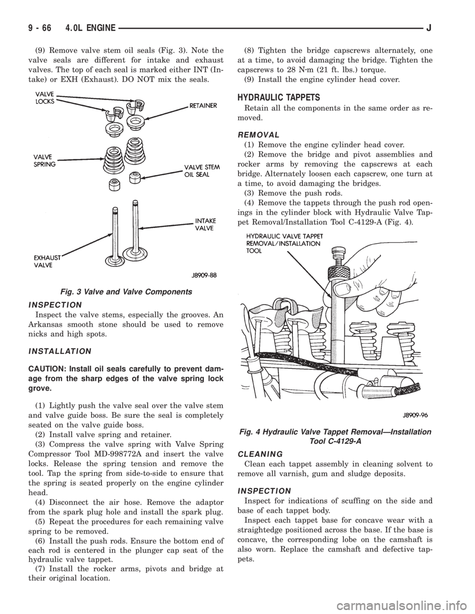
(9) Remove valve stem oil seals (Fig. 3). Note the
valve seals are different for intake and exhaust
valves. The top of each seal is marked either INT (In-
take) or EXH (Exhaust). DO NOT mix the seals.
INSPECTION
Inspect the valve stems, especially the grooves. An
Arkansas smooth stone should be used to remove
nicks and high spots.
INSTALLATION
CAUTION: Install oil seals carefully to prevent dam-
age from the sharp edges of the valve spring lock
grove.
(1) Lightly push the valve seal over the valve stem
and valve guide boss. Be sure the seal is completely
seated on the valve guide boss.
(2) Install valve spring and retainer.
(3) Compress the valve spring with Valve Spring
Compressor Tool MD-998772A and insert the valve
locks. Release the spring tension and remove the
tool. Tap the spring from side-to-side to ensure that
the spring is seated properly on the engine cylinder
head.
(4) Disconnect the air hose. Remove the adaptor
from the spark plug hole and install the spark plug.
(5) Repeat the procedures for each remaining valve
spring to be removed.
(6) Install the push rods. Ensure the bottom end of
each rod is centered in the plunger cap seat of the
hydraulic valve tappet.
(7) Install the rocker arms, pivots and bridge at
their original location.(8) Tighten the bridge capscrews alternately, one
at a time, to avoid damaging the bridge. Tighten the
capscrews to 28 Nzm (21 ft. lbs.) torque.
(9) Install the engine cylinder head cover.
HYDRAULIC TAPPETS
Retain all the components in the same order as re-
moved.
REMOVAL
(1) Remove the engine cylinder head cover.
(2) Remove the bridge and pivot assemblies and
rocker arms by removing the capscrews at each
bridge. Alternately loosen each capscrew, one turn at
a time, to avoid damaging the bridges.
(3) Remove the push rods.
(4) Remove the tappets through the push rod open-
ings in the cylinder block with Hydraulic Valve Tap-
pet Removal/Installation Tool C-4129-A (Fig. 4).
CLEANING
Clean each tappet assembly in cleaning solvent to
remove all varnish, gum and sludge deposits.
INSPECTION
Inspect for indications of scuffing on the side and
base of each tappet body.
Inspect each tappet base for concave wear with a
straightedge positioned across the base. If the base is
concave, the corresponding lobe on the camshaft is
also worn. Replace the camshaft and defective tap-
pets.
Fig. 3 Valve and Valve Components
Fig. 4 Hydraulic Valve Tappet RemovalÐInstallation
Tool C-4129-A
9 - 66 4.0L ENGINEJ
Page 1358 of 2158
LUBRICATION SYSTEM
A gearÐtype positive displacement pump is
mounted at the underside of the block opposite the
No. 4 main bearing. The pump draws oil through the
screen and inlet tube from the sump at the rear of
the oil pan. The oil is driven between the drive and
idler gears and pump body, then forced through the
outlet to the block. An oil gallery in the block chan-
nels the oil to the inlet side of the full flow oil filter.
After passing through the filter element, the oil
passes from the center outlet of the filter through an
oil gallery that channels the oil up to the main gal-
lery which extends the entire length of the block.
Galleries extend downward from the main oil gal-
lery to the upper shell of each main bearing. The
crankshaft is drilled internally to pass oil from the
main bearing journals (except number 4 main bear-
ing journal) to the connecting rod journals. Each con-
necting rod bearing cap has a small squirt hole, oilpasses through the squirt hole and is thrown off as
the rod rotates. This oil throwoff lubricates the cam-
shaft lobes, distributor drive gear, cylinder walls, and
piston pins.
The hydraulic valve tappets receive oil directly
from the main oil gallery. Oil is provided to the cam-
shaft bearing through galleries. The front camshaft
bearing journal passes oil through the camshaft
sprocket to the timing chain. Oil drains back to the
oil pan under the number one main bearing cap.
The oil supply for the rocker arms and bridged
pivot assemblies is provided by the hydraulic valve
tappets which pass oil through hollow push rods to a
hole in the corresponding rocker arm. Oil from the
rocker arm lubricates the valve train components,
then passes down through the push rod guide holes
in the cylinder head past the valve tappet area, and
returns to the oil pan.
J4.0L ENGINE 9 - 79
Page 1376 of 2158
EXHAUST SYSTEM AND INTAKE MANIFOLD
CONTENTS
page page
EXHAUST SYSTEM....................... 1
EXHAUST SYSTEM DIAGNOSIS............. 2SERVICE PROCEDURES................... 3
TORQUE SPECIFICATIONS................ 10
EXHAUST SYSTEM
GENERAL INFORMATION
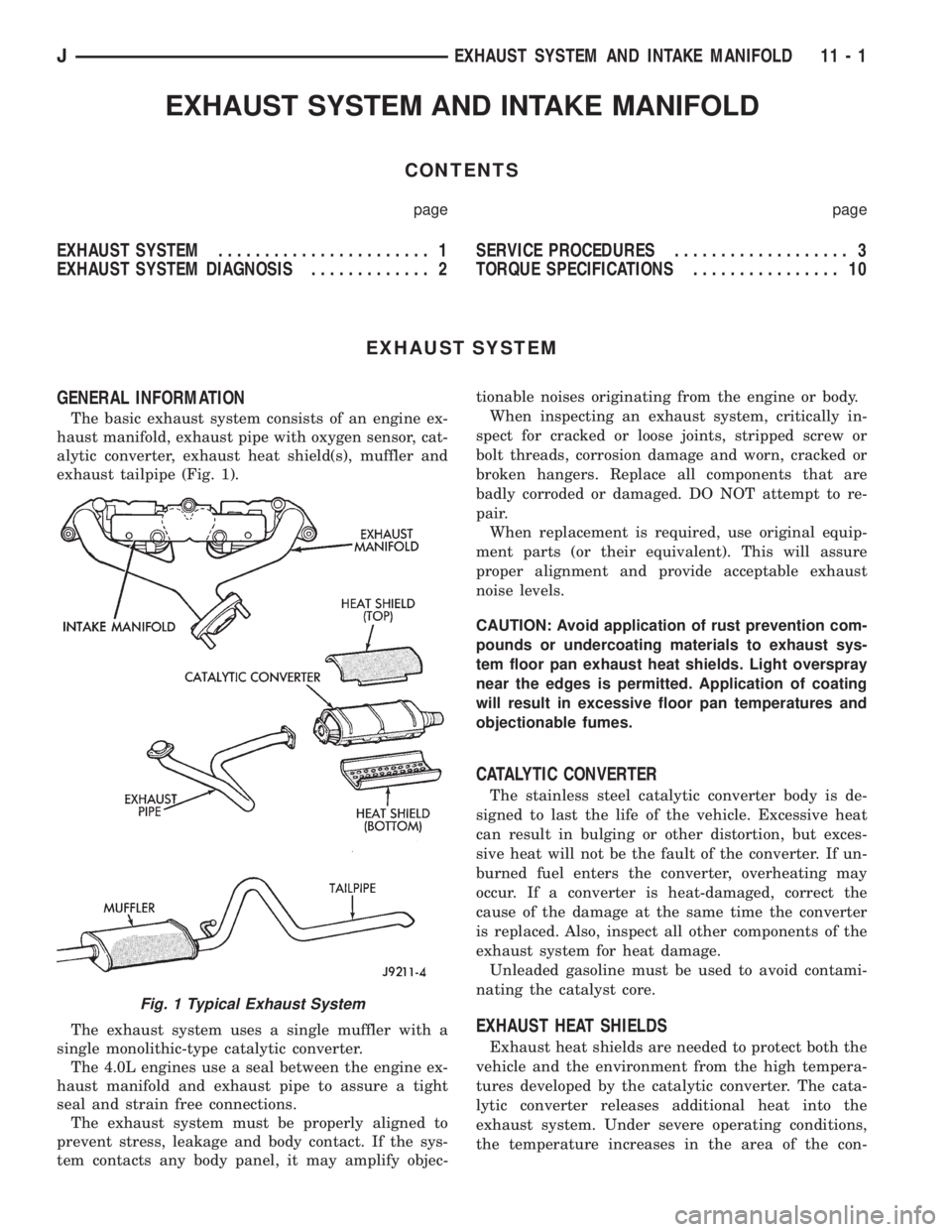
The basic exhaust system consists of an engine ex-
haust manifold, exhaust pipe with oxygen sensor, cat-
alytic converter, exhaust heat shield(s), muffler and
exhaust tailpipe (Fig. 1).
The exhaust system uses a single muffler with a
single monolithic-type catalytic converter.
The 4.0L engines use a seal between the engine ex-
haust manifold and exhaust pipe to assure a tight
seal and strain free connections.
The exhaust system must be properly aligned to
prevent stress, leakage and body contact. If the sys-
tem contacts any body panel, it may amplify objec-tionable noises originating from the engine or body.
When inspecting an exhaust system, critically in-
spect for cracked or loose joints, stripped screw or
bolt threads, corrosion damage and worn, cracked or
broken hangers. Replace all components that are
badly corroded or damaged. DO NOT attempt to re-
pair.
When replacement is required, use original equip-
ment parts (or their equivalent). This will assure
proper alignment and provide acceptable exhaust
noise levels.
CAUTION: Avoid application of rust prevention com-
pounds or undercoating materials to exhaust sys-
tem floor pan exhaust heat shields. Light overspray
near the edges is permitted. Application of coating
will result in excessive floor pan temperatures and
objectionable fumes.
CATALYTIC CONVERTER
The stainless steel catalytic converter body is de-
signed to last the life of the vehicle. Excessive heat
can result in bulging or other distortion, but exces-
sive heat will not be the fault of the converter. If un-
burned fuel enters the converter, overheating may
occur. If a converter is heat-damaged, correct the
cause of the damage at the same time the converter
is replaced. Also, inspect all other components of the
exhaust system for heat damage.
Unleaded gasoline must be used to avoid contami-
nating the catalyst core.
EXHAUST HEAT SHIELDS
Exhaust heat shields are needed to protect both the
vehicle and the environment from the high tempera-
tures developed by the catalytic converter. The cata-
lytic converter releases additional heat into the
exhaust system. Under severe operating conditions,
the temperature increases in the area of the con-
Fig. 1 Typical Exhaust System
JEXHAUST SYSTEM AND INTAKE MANIFOLD 11 - 1
Page 1382 of 2158
INSTALLATION
(1) Install the muffler onto the catalytic converter
outlet. Ensure that the locator on the converter
aligns with the notch on the muffler, if so equipped.
Install the clamp and tighten the nuts finger tight.
(2) Install the exhaust tailpipe into the muffler
outlet. Ensure that the locator on the exhaust
tailpipe aligns with the notch on the muffler, if so
equipped. Install the clamp and tighten the nuts fin-
ger tight.
(3) Install the front exhaust tailpipe supports and
the rear exhaust tailpipe hanger. Ensure that the ex-
haust tailpipe has sufficient clearance from the floor
pan and shields.
(4) Tighten the nuts on the muffler-to-catalytic
converter and the muffler-to-exhaust tailpipe clamps
to 61 Nzm (45 ft. lbs.) torque.
(5) Lower the vehicle.
(6) Start the engine and inspect for exhaust leaks
and contact with the body panels and shields.
ENGINE EXHAUST MANIFOLDÐ2.5L ENGINE
REMOVAL
(1) Disconnect the battery negative cable.
(2) Remove all components attached to the intake
manifold.
(3) Raise the vehicle.
(4) Disconnect the exhaust pipe from the engine
exhaust manifold.
(5) Lower the vehicle.
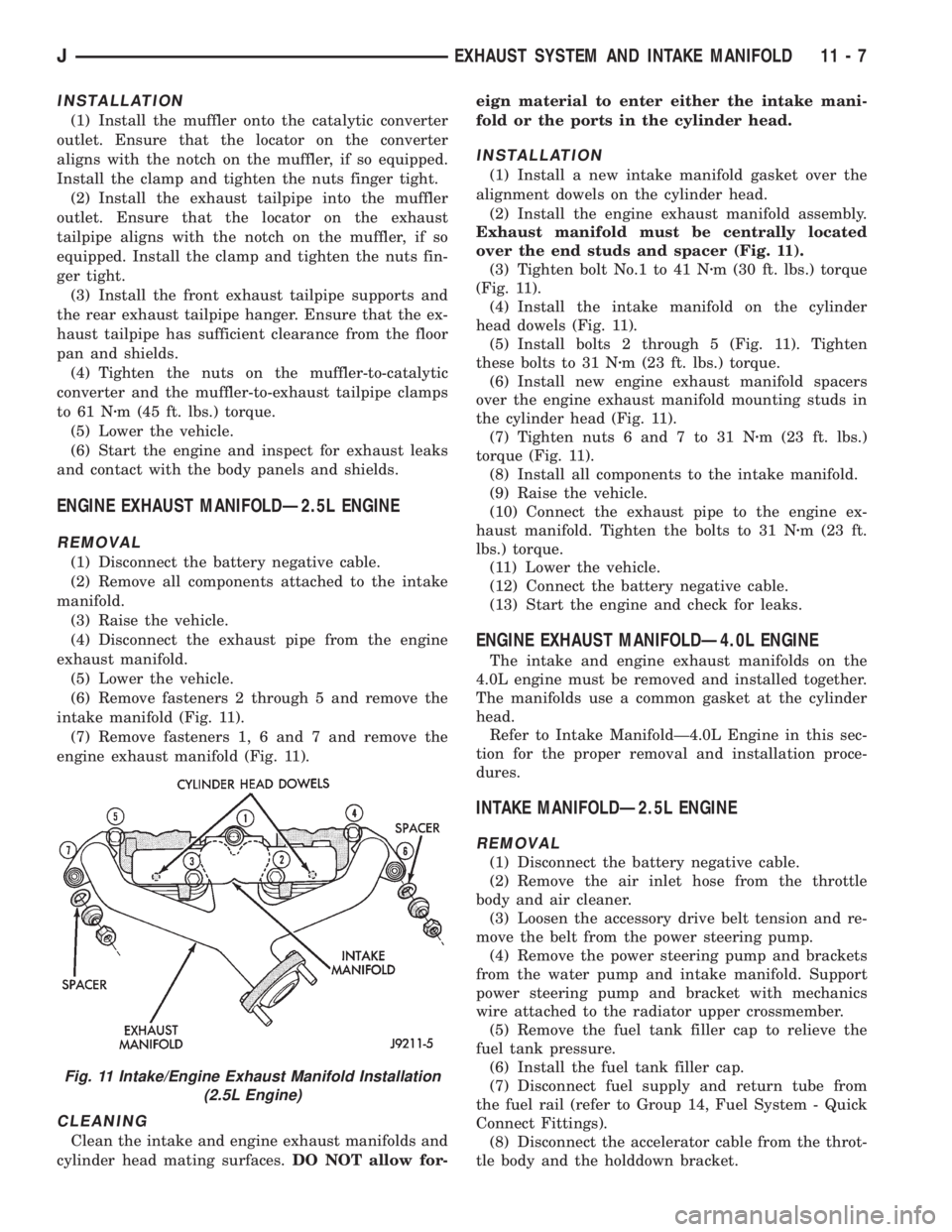
(6) Remove fasteners 2 through 5 and remove the
intake manifold (Fig. 11).
(7) Remove fasteners 1, 6 and 7 and remove the
engine exhaust manifold (Fig. 11).
CLEANING
Clean the intake and engine exhaust manifolds and
cylinder head mating surfaces.DO NOT allow for-eign material to enter either the intake mani-
fold or the ports in the cylinder head.
INSTALLATION
(1) Install a new intake manifold gasket over the
alignment dowels on the cylinder head.
(2) Install the engine exhaust manifold assembly.
Exhaust manifold must be centrally located
over the end studs and spacer (Fig. 11).
(3) Tighten bolt No.1 to 41 Nzm (30 ft. lbs.) torque
(Fig. 11).
(4) Install the intake manifold on the cylinder
head dowels (Fig. 11).
(5) Install bolts 2 through 5 (Fig. 11). Tighten
these bolts to 31 Nzm (23 ft. lbs.) torque.
(6) Install new engine exhaust manifold spacers
over the engine exhaust manifold mounting studs in
the cylinder head (Fig. 11).
(7) Tighten nuts 6 and 7 to 31 Nzm (23 ft. lbs.)
torque (Fig. 11).
(8) Install all components to the intake manifold.
(9) Raise the vehicle.
(10) Connect the exhaust pipe to the engine ex-
haust manifold. Tighten the bolts to 31 Nzm (23 ft.
lbs.) torque.
(11) Lower the vehicle.
(12) Connect the battery negative cable.
(13) Start the engine and check for leaks.
ENGINE EXHAUST MANIFOLDÐ4.0L ENGINE
The intake and engine exhaust manifolds on the
4.0L engine must be removed and installed together.
The manifolds use a common gasket at the cylinder
head.
Refer to Intake ManifoldÐ4.0L Engine in this sec-
tion for the proper removal and installation proce-
dures.
INTAKE MANIFOLDÐ2.5L ENGINE
REMOVAL
(1) Disconnect the battery negative cable.
(2) Remove the air inlet hose from the throttle
body and air cleaner.
(3) Loosen the accessory drive belt tension and re-
move the belt from the power steering pump.
(4) Remove the power steering pump and brackets
from the water pump and intake manifold. Support
power steering pump and bracket with mechanics
wire attached to the radiator upper crossmember.
(5) Remove the fuel tank filler cap to relieve the
fuel tank pressure.
(6) Install the fuel tank filler cap.
(7) Disconnect fuel supply and return tube from
the fuel rail (refer to Group 14, Fuel System - Quick
Connect Fittings).
(8) Disconnect the accelerator cable from the throt-
tle body and the holddown bracket.
Fig. 11 Intake/Engine Exhaust Manifold Installation
(2.5L Engine)
JEXHAUST SYSTEM AND INTAKE MANIFOLD 11 - 7
Page 1386 of 2158
FRAME AND BUMPERS
CONTENTS
page page
BUMPERS.............................. 5
BUMPERS............................. 16FRAME................................. 1
FRAME................................ 10
FRAME
INDEX
page page
Frame Dimensions......................... 1
Front Skid Plate........................... 1
Fuel Filler Hose Splash ShieldÐXJ Vehicles...... 4
Fuel Tank Skid Plate........................ 3Fuel Tank Support Strap..................... 4
General Information........................ 1
Transfer Case Skid Plate.................... 3
GENERAL INFORMATION
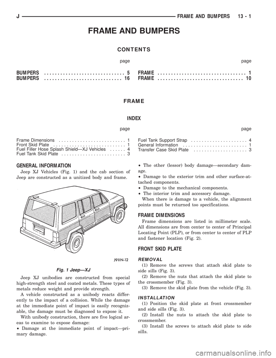
Jeep XJ Vehicles (Fig. 1) and the cab section of
Jeep are constructed as a unitized body and frame.
Jeep XJ unibodies are constructed from special
high-strength steel and coated metals. These types of
metals reduce weight and provide strength.
A vehicle constructed as a unibody reacts differ-
ently to the impact of a collision. While the damage
at the immediate point of impact is easily recogniz-
able, the damage must be diagnosed to expose it.
With unibody construction, there are five logical ar-
eas to examine to expose damage:
²Damage at the immediate point of impactÐpri-
mary damage.²The other (lessor) body damageÐsecondary dam-
age.
²Damage to the exterior trim and other surface-at-
tached components.
²Damage to the mechanical components.
²The interior trim and accessory damage.
When there is damage to a vehicle, the alignment
points must be returned too specifications.
FRAME DIMENSIONS
Frame dimensions are listed in millimeter scale.
All dimensions are from center to center of Principal
Locating Point (PLP), or from center to center of PLP
and fastener location (Fig. 2).
FRONT SKID PLATE
REMOVAL
(1) Remove the screws that attach skid plate to
side sills (Fig. 3).
(2) Remove the nuts that attach the skid plate to
the crossmember (Fig. 3).
(3) Remove the skid plate from the vehicle (Fig. 3).
INSTALLATION
(1) Position the skid plate at front crossmember
and side sills (Fig. 3).
(2) Install the nuts to attach the skid plate to
crossmember.
(3) Install the screws to attach skid plate to side
sills.
Fig. 1 JeepÐXJ
JFRAME AND BUMPERS 13 - 1
Page 1390 of 2158
BUMPERS
INDEX
page page
Front Bumper............................. 5
Front Tow Hooks........................... 7Rear Bumper............................. 8
Rear Tow Hook............................ 9
FRONT BUMPER
REMOVAL/DISASSEMBLY
(1) The bumper guards, end caps and tow hooks can
be removed from XJ front bumpers with the bumper at-
tached to the vehicle. Do not remove the bumper from
the vehicle if only these components require service.
If equipped with a brush guard, refer to the Brush
Guard Removal within Group 23, Body Components.(2) Disconnect the fog lamp wire harness connec-
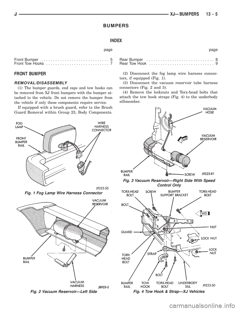
tors, if equipped (Fig. 1).
(3) Disconnect the vacuum reservoir tube harness
connectors (Fig. 2 and 3).
(4) Remove the locknuts and Torx-head bolts that
attach the tow hook straps (Fig. 4) to the underbody
sillmember.
Fig. 1 Fog Lamp Wire Harness Connector
Fig. 2 Vacuum ReservoirÐLeft Side
Fig. 3 Vacuum ReservoirÐRight Side With Speed
Control Only
Fig. 4 Tow Hook & StrapÐXJ Vehicles
JXJÐBUMPERS 13 - 5