1995 JEEP YJ ECU
[x] Cancel search: ECUPage 203 of 2158

CALIPER INSTALLATION
(1) Install brakeshoes in caliper (Figs. 11, 12).
(2) Connect brake hose to caliper but do not
tighten fitting bolt completely at this time.Be sure
to use new gaskets on fitting bolt to avoid leaks
(Fig. 25).
(3) Install caliper. Position mounting notches at
lower end of brakeshoes on bottom mounting ledge
(Fig. 13). Then rotate caliper over rotor and seat
notches at upper end of shoes on mounting ledge
(Fig. 13).
(4) Coat caliper mounting bolts with GE 661 or
Dow 111 silicone grease. Then install and tighten
bolts to 10-20 Nzm (7-15 ft. lbs.) torque.CAUTION: If new caliper bolts are being installed,
or if the original reason for repair was a drag/pull
condition, check caliper bolt length before proceed-
ing. If the bolts have a shank length greater than
67.6 mm (2.66 in.), they may contact the inboard
brakeshoe causing a partial apply condition. Refer
to Figure 14 for the required caliper bolt length.
(5) Position front brake hose clear of all chassis
components and tighten caliper fitting bolt to 31 Nzm
(23 ft. lbs.) torque.
CAUTION: Be sure the brake hose is not twisted or
kinked at any point. Also be sure the hose is clear
of all steering and suspension components. Loosen
and reposition the hose if necessary.
(6) Install wheels. Tighten wheel lug nuts to 109-
150 Nzm (80-110 ft. lbs.) torque.
(7) Fill and bleed brake system. Refer to proce-
dures in Service Adjustments section.
ROTOR REMOVAL
(1) Raise vehicle and remove wheel.
(2) Remove caliper.
(3) Remove retainers securing rotor to hub studs
(Fig. 26).
(4) Remove rotor from hub (Fig. 26).
(5) If rotor shield requires service, remove front
hub and bearing assembly.
ROTOR INSTALLATION
(1) If new rotor is being installed, remove protec-
tive coating from rotor surfaces with Mopar carb
cleaner.It is not necessary to machine a rotor to
remove the coating. Mopar carb cleaner fol-
lowed by a rinse with brake cleaner will re-
move the coating.
(2) Install rotor on hub.
(3) Install caliper.
Fig. 23 Installing Caliper Piston
Fig. 24 Seating Caliper Piston Dust Boot
Fig. 25 Front Brake Hose And Fitting Components
JDISC BRAKES 5 - 51
Page 204 of 2158

(4) Install new spring nuts on wheel studs.
(5) Install wheel and lower vehicle.
DISC BRAKE ROTOR THICKNESS
Rotor minimum usable thickness is 22.7 mm (0.89
in.). This dimension is either cast, or stamped on the
rotor hub, or outer edge.
Measure rotor thickness at the center of the brake-
shoe contact surface.
Replace the rotor if worn below minimum thick-
ness. Also replace the rotor if refinishing would re-
duce thickness below the allowable minimum.
DISC BRAKE ROTOR RUNOUT
Check rotor lateral runout whenever pedal pulsa-
tion, or rapid, uneven brakelining wear has occurred.
On 4-wheel drive models, the rotor must be se-
curely clamped to the hub to ensure an accurate
runout measurement. Secure the rotor with the
wheel nuts and 4 or 5 large diameter flat washers on
each stud as shown (Fig. 27).
Use a dial indicator to check lateral runout (Fig.
27).
Maximum allowable rotor lateral runout is 0.13
mm (0.005 in.).
Check lateral runout with a dial indicator (Fig. 28).
Excessive lateral runout will cause brake pedal pul-
sation and rapid, uneven wear of the brakeshoes.
Maximum allowable rotor runout for all models is
0.12 mm (0.005 in.).
DISC BRAKE ROTOR THICKNESS VARIATION
Variations in rotor thickness will cause pedal pul-
sation, noise and shudder.
Measure rotor thickness at four to six points
around the rotor face. Position the micrometer ap-
proximately 2 cm (3/4 in.) from the rotor outer cir-
cumference for each measurement (Fig. 29).
Thickness should notvaryby more than 0.013 mm
(0.0005 in.) from point-to-point on the rotor. Refinish
or replace the rotor if necessary.
Fig. 26 Rotor And HubFig. 27 Securing4x4Rotor For Lateral Runout Check
Fig. 28 Typical Method Of Checking Rotor Lateral
Runout
Fig. 29 Measuring Rotor Thickness Variation
5 - 52 DISC BRAKESJ
Page 207 of 2158

DRUM BRAKES
INDEX
page page
Brake Drum Refinishing.................... 58
Drum Brake Adjustment.................... 57
Drum Brakeshoe Installation................. 55
Drum Brakeshoe Removal................... 55
Support Plate Replacement.................. 58Wheel Cylinder Installation.................. 58
Wheel Cylinder Overhaul.................... 57
Wheel Cylinder Removal.................... 57
Wheel Nut Tightening...................... 59
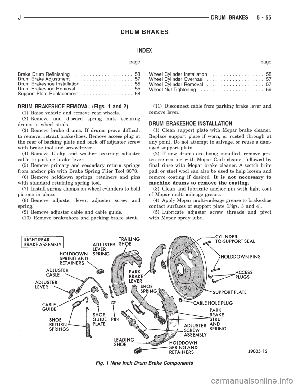
DRUM BRAKESHOE REMOVAL (Figs. 1 and 2)
(1) Raise vehicle and remove rear wheels.
(2) Remove and discard spring nuts securing
drums to wheel studs.
(3) Remove brake drums. If drums prove difficult
to remove, retract brakeshoes. Remove access plug at
the rear of backing plate and back off adjuster screw
with brake tool and screwdriver.
(4) Remove U-clip and washer securing adjuster
cable to parking brake lever.
(5) Remove primary and secondary return springs
from anchor pin with Brake Spring Plier Tool 8078.
(6) Remove holddown springs, retainers and pins
with standard retaining spring tool.
(7) Install spring clamps on wheel cylinders to hold
pistons in place.
(8) Remove adjuster lever, adjuster screw and
spring.
(9) Remove adjuster cable and cable guide.
(10) Remove brakeshoes and parking brake strut.(11) Disconnect cable from parking brake lever and
remove lever.
DRUM BRAKESHOE INSTALLATION
(1) Clean support plate with Mopar brake cleaner.
Replace support plate if worn, or rusted through at
any point. Do not attempt to salvage, or reuse a dam-
aged support plate.
(2) If new drums are being installed, remove pro-
tective coating with Mopar Carb cleaner followed by
final rinse with Mopar brake cleaner. A scotch brite
pad, or steel wool can also be used to help loosen and
remove coating if desired.It is not necessary to
machine drums to remove the coating.
(3) Clean and lubricate anchor pin with light coat
of Mopar multi-mileage grease.
(4) Apply Mopar multi-mileage grease to brakeshoe
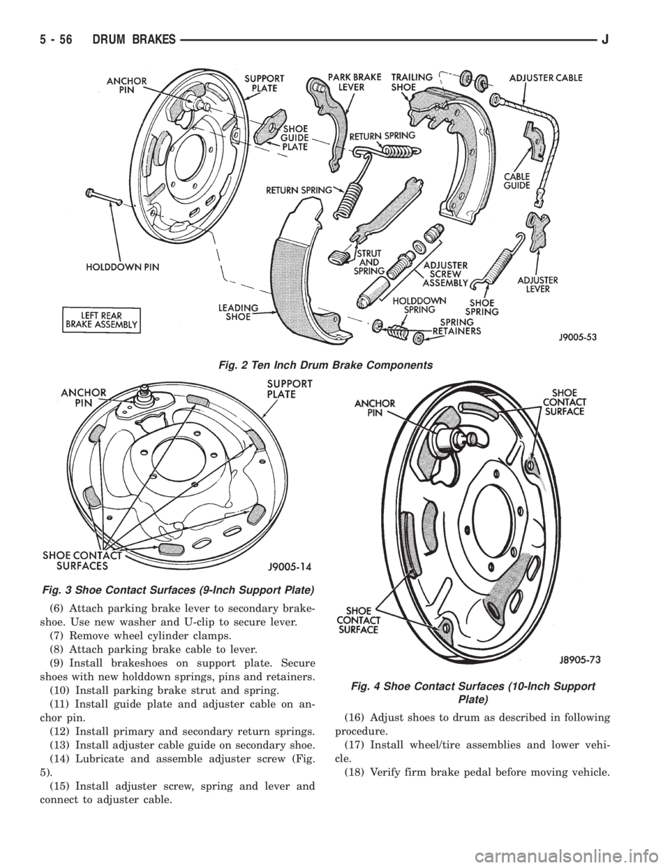
contact surfaces of support plate (Figs. 3 and 4).
(5) Lubricate adjuster screw threads and pivot
with Mopar spray lube.
Fig. 1 Nine Inch Drum Brake Components
JDRUM BRAKES 5 - 55
Page 208 of 2158

(6) Attach parking brake lever to secondary brake-
shoe. Use new washer and U-clip to secure lever.
(7) Remove wheel cylinder clamps.
(8) Attach parking brake cable to lever.
(9) Install brakeshoes on support plate. Secure
shoes with new holddown springs, pins and retainers.
(10) Install parking brake strut and spring.
(11) Install guide plate and adjuster cable on an-
chor pin.
(12) Install primary and secondary return springs.
(13) Install adjuster cable guide on secondary shoe.
(14) Lubricate and assemble adjuster screw (Fig.
5).
(15) Install adjuster screw, spring and lever and
connect to adjuster cable.(16) Adjust shoes to drum as described in following
procedure.
(17) Install wheel/tire assemblies and lower vehi-
cle.
(18) Verify firm brake pedal before moving vehicle.
Fig. 2 Ten Inch Drum Brake Components
Fig. 3 Shoe Contact Surfaces (9-Inch Support Plate)
Fig. 4 Shoe Contact Surfaces (10-Inch Support
Plate)
5 - 56 DRUM BRAKESJ
Page 213 of 2158

secondary brakeshoes move the shoes directly into
contact with the drum braking surface. The actuating
levers are interconnected by a system of cables and a
tensioner mechanism. The tensioner mechanism con-
trols parking brake adjustment.
A parking brake switch is used on all models. It is
mounted on the parking brake lever or foot pedal and
is actuated by movement of the lever/pedal. The
switch, which is in circuit with the red warning light
in the dash, will illuminate the warning light when-
ever the parking brakes are applied.
On XJ models, the cable tensioner is part of the lever
assembly. On YJ models, the tensioner and equalizer
are mounted in a bracket attached to the underbody.
On YJ models, the parking brake front cable is at-
tached to the foot pedal and cable tensioner. The ten-
sioner and rear cables are connected to the equalizer
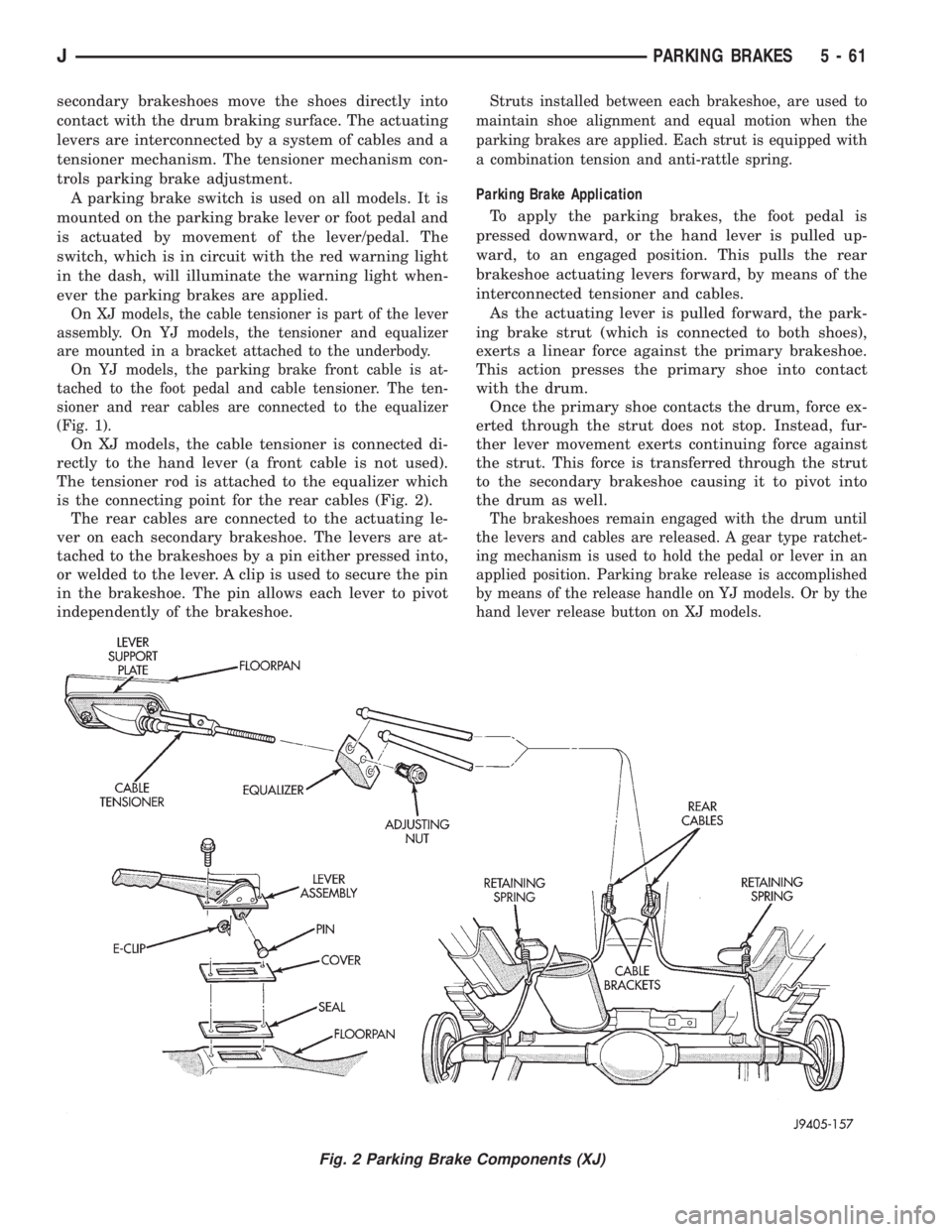
(Fig. 1).
On XJ models, the cable tensioner is connected di-
rectly to the hand lever (a front cable is not used).
The tensioner rod is attached to the equalizer which
is the connecting point for the rear cables (Fig. 2).
The rear cables are connected to the actuating le-
ver on each secondary brakeshoe. The levers are at-
tached to the brakeshoes by a pin either pressed into,
or welded to the lever. A clip is used to secure the pin
in the brakeshoe. The pin allows each lever to pivot
independently of the brakeshoe.
Struts installed between each brakeshoe, are used to
maintain shoe alignment and equal motion when the
parking brakes are applied. Each strut is equipped with
a combination tension and anti-rattle spring.
Parking Brake Application
To apply the parking brakes, the foot pedal is
pressed downward, or the hand lever is pulled up-
ward, to an engaged position. This pulls the rear
brakeshoe actuating levers forward, by means of the
interconnected tensioner and cables.
As the actuating lever is pulled forward, the park-
ing brake strut (which is connected to both shoes),
exerts a linear force against the primary brakeshoe.
This action presses the primary shoe into contact
with the drum.
Once the primary shoe contacts the drum, force ex-
erted through the strut does not stop. Instead, fur-
ther lever movement exerts continuing force against
the strut. This force is transferred through the strut
to the secondary brakeshoe causing it to pivot into
the drum as well.
The brakeshoes remain engaged with the drum until
the levers and cables are released. A gear type ratchet-
ing mechanism is used to hold the pedal or lever in an
applied position. Parking brake release is accomplished
by means of the release handle on YJ models. Or by the
hand lever release button on XJ models.
Fig. 2 Parking Brake Components (XJ)
JPARKING BRAKES 5 - 61
Page 214 of 2158

PARKING BRAKE LEVER REMOVAL (XJ WITH MINI
CONSOLE)
(1) Release parking brakes, if necessary.
(2) Raise vehicle.
(3) Remove adjusting nut from tensioner rod (Fig.
2). Then secure equalizer and rear cables to chassis
with wire.
(4) Remove nuts attaching lever support plate to
underside of floorpan. Then move plate aside.
(5) Lower vehicle.(6) Disconnect parking brake switch wire at switch
(Fig. 3).
(7) Remove parking brake lever assembly from
floorpan.
(8) Remove tensioner cover and boot for access to
lever arm (Fig. 4).
(9) Remove E-clip and pin that connect tensioner
to lever arm (Fig. 4).
(10) Remove lever attaching screws from floorpan
(Fig. 5).
(11) Remove lever assembly.
Fig. 3 Parking Brake Switch MountingFig. 4 Tensioner E-Clip And Retaining Pin Location
Fig. 5 Mini Console And Parking Brake Lever Cover (XJ)
5 - 62 PARKING BRAKESJ
Page 215 of 2158

(12) Parking brake switch can be serviced at this
time, if necessary.
PARKING BRAKE LEVER INSTALLATION (XJ WITH
MINI CONSOLE)
(1) Assemble lever and tensioner components (Figs.
4 and 5). Be sure E-clip is fully seated in pin (Fig. 4).
(2) Verify that tensioner boot is properly seated in
cover (Fig. 6).
(3) Position lever assembly on floorpan and install
lever attaching screws/nuts. Also install parking
brake switch if removed, or replaced.
(4) Raise vehicle.
(5) Insert cable tensioner rod in equalizer and in-
stall adjusting nut on tensioner rod (Fig. 7).
(6) Install and tighten nuts that attach lever sup-
port plate to floorpan and lever screws.
(7) Adjust parking brakes. Refer to procedure in
this section.
(8) Lower vehicle.
(9) Connect parking brake switch wire.
(10) Install lever trim cover, if equipped.(11) Verify correct parking brake operation.
PARKING BRAKE LEVER REMOVAL (XJ WITH FULL
CONSOLE)
(1) Release parking brakes.
(2) Raise vehicle.
(3) Remove adjusting nut from tensioner rod. Then
temporarily secure equalizer to nearby chassis com-
ponent with wire.
(4) Remove nuts attaching lever support plate to
underside of floorpan.
(5) Lower vehicle.
(6) On models with manual transmission, remove
shift knob, outer boot, and bezel.
(7) On models with automatic transmission, re-
move shift handle cap and remove plunger, spring
and T-lock (Fig. 8).
Fig. 7 Hand Lever And Cable Tensioner Components (XJ)
Fig. 6 Tensioner Boot Seated In Cover
Fig. 8 Automatic Transmission Shift Handle And Bezel
JPARKING BRAKES 5 - 63
Page 217 of 2158

(3) Remove adjusting nut from tensioner rod. Then
temporarily secure equalizer and cables to nearby
chassis component with wire.
(4) Lower vehicle.
(5) Raise lever cover at rear and tilt it forward
(Fig. 12).
(6) Remove cover attaching screws. Or, if cover is
attached with rivets, drill out and remove cover.
(7) Disconnect parking brake warning light wire at
switch on lever. Remove switch if replacement is nec-
essary.
(8) Remove lever and tensioner assembly from
floorpan.
(9) Move cover and boot aside for access to ten-
sioner retaining pin and clip.
(10) Remove pin and E-clip that secure tensioner
to lever arm and separate lever and tensioner.PARKING BRAKE LEVER INSTALLATION (XJ
WITHOUT CONSOLE)
(1) Assemble lever and tensioner (Figs. 4 and 5).
(2) Verify that tensioner boot is properly seated in
cover (Fig. 6).
(3) Position lever on floorpan and insert lever
screws through floorpan. Be sure lever cover and seal
are in place between lever and floorpan.
(4) Install parking brake switch on lever, if re-
moved, and connect warning light wires to switch.
(5) Install lever cover. Secure cover with new riv-
ets, or original attaching screws.
(6) Raise vehicle.
(7) Connect tensioner to lever with retaining pin
and E-clip.
(8) Install nuts attaching lever support plate to le-
ver screws.
(9) Adjust parking brakes. Refer to procedure in
this section.
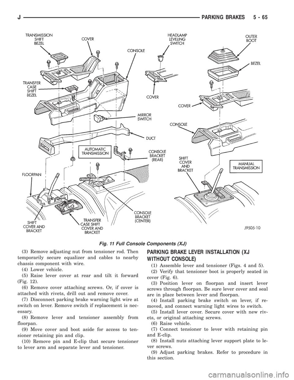
Fig. 11 Full Console Components (XJ)
JPARKING BRAKES 5 - 65