1995 JEEP YJ transmission
[x] Cancel search: transmissionPage 183 of 2158

(5) Connect vacuum hose to brake booster check
valve.
(6) Install master cylinder and combination valve.
(7) Bleed brakes. Then tighten brakeline fittings to
15-18 Nzm (130-160 in. lbs.) at master cylinder and
18-24 Nzm (160-210 in. lbs.) at combination valve.
BRAKE PEDAL REMOVAL
(1) Remove lower trim panel and A/C duct if nec-
essary.
(2) Remove steering column lower trim panel and
bezel.(3) Remove necessary dash panel-to-instrument
panel brace rods.
(4) Disconnect and remove brakelight switch.
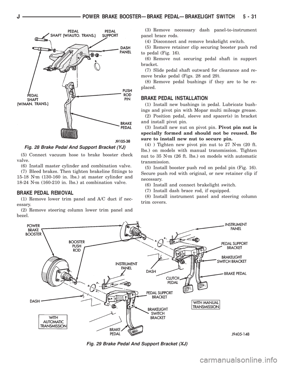
(5) Remove retainer clip securing booster push rod
to pedal (Fig. 16).
(6) Remove nut securing pedal shaft in support
bracket.
(7) Slide pedal shaft outward for clearance and re-
move brake pedal (Figs. 28 and 29).
(8) Remove pedal bushings if they are to be re-
placed.
BRAKE PEDAL INSTALLATION
(1) Install new bushings in pedal. Lubricate bush-
ings and pivot pin with Mopar multi mileage grease.
(2) Position pedal, sleeve and spacer(s) in bracket
and install pivot pin.
(3) Install new nut on pivot pin.Pivot pin nut is
specially formed and should not be reused. Be
sure to install new nut to secure pin.
(4) ) Tighten new pivot pin nut to 27 Nzm (20 ft.
lbs.) on models with manual transmission. Tighten
nut to 35 Nzm (26 ft. lbs.) on models with automatic
transmission.
(5) Install booster push rod on pedal pin (Fig. 16).
Secure push rod with original, or new retainer clip if
necessary.
(6) Install and connect brakelight switch.
(7) Install dash brace rod, if equipped.
(8) Install instrument panel and steering column
trim covers.
Fig. 28 Brake Pedal And Support Bracket (YJ)
Fig. 29 Brake Pedal And Support Bracket (XJ)
JPOWER BRAKE BOOSTERÐBRAKE PEDALÐBRAKELIGHT SWITCH 5 - 31
Page 187 of 2158

ABS DIAGNOSTIC CONNECTOR
The ABS diagnostic connector is inside the vehicle.
The connector is the access point for the DRB scan
tool.
On XJ models, the connector is located under the
instrument panel to the right of the steering column.
On some models, the connecter may be tucked under
the carpeting on the transmission tunnel. The con-
necter is a black, 6-way type.
On YJ models, the connector is under the instru-
ment panel by the the driver side kick panel. The
connecter is a black, 6 or 8-way type.
The DRB scan tool kit contains adapter cords for
both types of connecter. Use the appropriate cord for
test hookup.
ACCELERATION SWITCH
An acceleration switch (Fig. 5), provides an addi-
tional vehicle deceleration reference during 4-wheel
drive operation. The switch is monitored by the an-
tilock ECU at all times. The switch reference signal
is utilized by the ECU when all wheels are deceler-
ating at the same speed.
SYSTEM RELAYS
The ABS system has two relays, which are the
main and motor pump relays. The motor pump relay
is used for the motor pump only. The main relay is
used for the solenoid valves and ECU. The main re-
lay is connected to the ECU at the power control re-
lay terminal. The pump motor relay starts/stops the
pump motor when signaled by the ECU.
IGNITION SWITCH
The antilock ECU and warning light are in standby
mode with the ignition switch in Off or Accessory po-
sition. No operating voltage is supplied to the system
components.A 12 volt power feed is supplied to the ECU and
warning light when the ignition switch is in the Run
position.
SYSTEM WARNING LIGHT
The amber ABS warning light is in circuit with the
ECU and operates independently of the red brake
warning light.
The ABS light indicates antilock system condition.
The light illuminates (flashes) at start-up for the self
check. The light goes out when the self check pro-
gram determines system operation is normal.
ABS SYSTEM POWER-UP AND INITIALIZATION
battery voltage is supplied to the ECU ignition ter-
minal when the ignition switch is turned to Run po-
sition. The ECU performs a system initialization
procedure at this point. Initialization consists of a
static and dynamic self check of system electrical
components.
The static check occurs after the ignition switch is
turned to Run position. The dynamic check occurs
when vehicle road speed reaches approximately 10
kph (6 mph). During the dynamic check, the ECU
briefly cycles the pump and solenoids to verify oper-
ation.
If an ABS component exhibits a fault during initial-
ization, the ECU illuminates the amber warning
light and registers a fault code in the microprocessor
memory.
ABS OPERATION IN NORMAL BRAKING MODE
The ECU monitors wheel speed sensor inputs con-
tinuously while the vehicle is in motion. However,
the ECU will not activate any ABS components as
long as sensor inputs and the acceleration switch in-
dicate normal braking.
Fig. 4 Wheel Speed SensorsFig. 5 Acceleration Switch
JABS OPERATION AND SERVICE 5 - 35
Page 215 of 2158

(12) Parking brake switch can be serviced at this
time, if necessary.
PARKING BRAKE LEVER INSTALLATION (XJ WITH
MINI CONSOLE)
(1) Assemble lever and tensioner components (Figs.
4 and 5). Be sure E-clip is fully seated in pin (Fig. 4).
(2) Verify that tensioner boot is properly seated in
cover (Fig. 6).
(3) Position lever assembly on floorpan and install
lever attaching screws/nuts. Also install parking
brake switch if removed, or replaced.
(4) Raise vehicle.
(5) Insert cable tensioner rod in equalizer and in-
stall adjusting nut on tensioner rod (Fig. 7).
(6) Install and tighten nuts that attach lever sup-
port plate to floorpan and lever screws.
(7) Adjust parking brakes. Refer to procedure in
this section.
(8) Lower vehicle.
(9) Connect parking brake switch wire.
(10) Install lever trim cover, if equipped.(11) Verify correct parking brake operation.
PARKING BRAKE LEVER REMOVAL (XJ WITH FULL
CONSOLE)
(1) Release parking brakes.
(2) Raise vehicle.
(3) Remove adjusting nut from tensioner rod. Then
temporarily secure equalizer to nearby chassis com-
ponent with wire.
(4) Remove nuts attaching lever support plate to
underside of floorpan.
(5) Lower vehicle.
(6) On models with manual transmission, remove
shift knob, outer boot, and bezel.
(7) On models with automatic transmission, re-
move shift handle cap and remove plunger, spring
and T-lock (Fig. 8).
Fig. 7 Hand Lever And Cable Tensioner Components (XJ)
Fig. 6 Tensioner Boot Seated In Cover
Fig. 8 Automatic Transmission Shift Handle And Bezel
JPARKING BRAKES 5 - 63
Page 216 of 2158

(8) Remove shift handle by pulling upward sharply
on handle. Then remove shift bezel (Fig. 7).
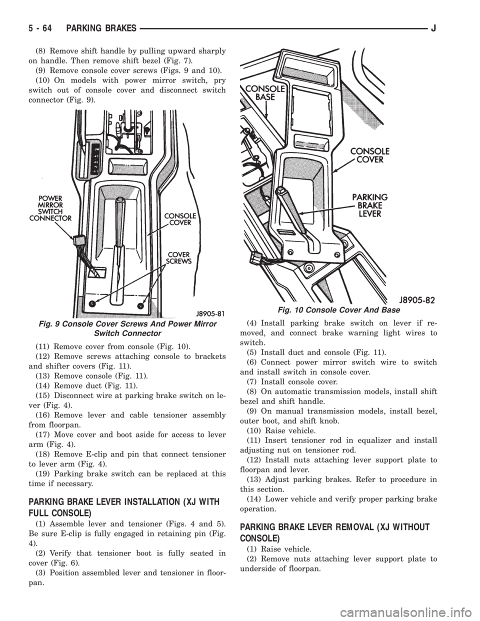
(9) Remove console cover screws (Figs. 9 and 10).
(10) On models with power mirror switch, pry
switch out of console cover and disconnect switch
connector (Fig. 9).
(11) Remove cover from console (Fig. 10).
(12) Remove screws attaching console to brackets
and shifter covers (Fig. 11).
(13) Remove console (Fig. 11).
(14) Remove duct (Fig. 11).
(15) Disconnect wire at parking brake switch on le-
ver (Fig. 4).
(16) Remove lever and cable tensioner assembly
from floorpan.
(17) Move cover and boot aside for access to lever
arm (Fig. 4).
(18) Remove E-clip and pin that connect tensioner
to lever arm (Fig. 4).
(19) Parking brake switch can be replaced at this
time if necessary.
PARKING BRAKE LEVER INSTALLATION (XJ WITH
FULL CONSOLE)
(1) Assemble lever and tensioner (Figs. 4 and 5).
Be sure E-clip is fully engaged in retaining pin (Fig.
4).
(2) Verify that tensioner boot is fully seated in
cover (Fig. 6).
(3) Position assembled lever and tensioner in floor-
pan.(4) Install parking brake switch on lever if re-
moved, and connect brake warning light wires to
switch.
(5) Install duct and console (Fig. 11).
(6) Connect power mirror switch wire to switch
and install switch in console cover.
(7) Install console cover.
(8) On automatic transmission models, install shift
bezel and shift handle.
(9) On manual transmission models, install bezel,
outer boot, and shift knob.
(10) Raise vehicle.
(11) Insert tensioner rod in equalizer and install
adjusting nut on tensioner rod.
(12) Install nuts attaching lever support plate to
floorpan and lever.
(13) Adjust parking brakes. Refer to procedure in
this section.
(14) Lower vehicle and verify proper parking brake
operation.PARKING BRAKE LEVER REMOVAL (XJ WITHOUT
CONSOLE)
(1) Raise vehicle.
(2) Remove nuts attaching lever support plate to
underside of floorpan.
Fig. 9 Console Cover Screws And Power Mirror
Switch Connector
Fig. 10 Console Cover And Base
5 - 64 PARKING BRAKESJ
Page 224 of 2158

CLUTCH OPERATION
Leverage, clamping force, and friction are what
make the clutch work. The disc serves as the friction
element and a diaphragm spring and pressure plate
provide the clamping force. The clutch pedal, hydrau-
lic linkage, release lever and bearing provide the le-
verage.
The clutch cover assembly clamps the disc against
the flywheel. The assembly consists of the cover, dia-
phragm spring, pressure plate, and fulcrum compo-
nents. The pressure plate clamps the clutch disc
against the flywheel and the spring provides the
clamping force.
The clutch disc friction material is riveted to the
disc hub. The hub bore is splined for installation on
the transmission input shaft. The hub splines con-
nect the disc to the transmission.
The clutch linkage uses hydraulic pressure to oper-
ate the clutch. The clutch master cylinder push rod is
connected to the clutch pedal and the slave cylinder
push rod is connected to the release lever in the
clutch housing.
Depressing the clutch pedal develops fluid pressure
in the clutch master cylinder. This pressure is trans-mitted to the slave cylinder through a connecting
line. In turn, the slave cylinder operates the clutch
release lever.
The clutch release bearing is mounted on the
transmission front bearing retainer. The bearing is
attached to the release lever, which moves the bear-
ing into contact with the clutch cover diaphragm
spring.
Slave cylinder force causes the release lever to
move the release bearing into contact with the dia-
phragm spring. As additional force is applied, the
bearing presses the diaphragm spring fingers inward
on the fulcrums. This action moves the pressure
plate rearward relieving clamp force on the disc. The
clutch disc is disengaged and freewheeling at this
point.
The process of clutch re-engagement, is simply the
reverse of what occurs during disengagement. Releas-
ing pedal pressure removes clutch linkage pressure.
The release bearing moves away from the diaphragm
spring which allows the pressure plate to exert
clamping force on the clutch disc.
6 - 2 CLUTCHJ
Page 225 of 2158

CLUTCH DIAGNOSIS
INDEX
page page
Clutch Contamination....................... 3
Clutch Cover and Disc Runout................ 3
Clutch Housing Misalignment................. 4
Clutch Misalignment........................ 3Flywheel Runout........................... 3
General Diagnosis Information................ 3
Inspection and Diagnosis Charts............... 4
Installation Methods and Parts Usage........... 4
GENERAL DIAGNOSIS INFORMATION
Unless the cause of a clutch problem is obvious, ac-
curate problem diagnosis will usually require a road
test to confirm a problem. Component inspection will
then be required to determine the actual problem
cause.
During a road test, drive the vehicle at normal
speeds. Shift the transmission through all gear
ranges and observe clutch action. If chatter, grab,
slip, or improper release is experienced, remove and
inspect the clutch components. However, if the prob-
lem is noise or hard shifting, further diagnosis may
be needed as the transmission or another driveline
component may be at fault. Careful observation dur-
ing the test will help narrow the problem area.
CLUTCH CONTAMINATION
Fluid contamination is a frequent cause of clutch
malfunctions. Oil, water, or clutch fluid on the clutch
disc and pressure plate surfaces will cause chatter,
slip and grab.
During inspection, note if any components are con-
taminated with oil, hydraulic fluid, or water/road
splash.
Oil contamination indicates a leak at either the
rear main seal or transmission input shaft. Oil leak-
age produces a residue of oil on the housing interior
and on the clutch cover and flywheel. Heat buildup
caused by slippage between the cover, disc and fly-
wheel, can sometimes bake the oil residue onto the
components. The glaze-like residue ranges in color
from amber to black.
Road splash contamination means dirt/water is en-
tering the clutch housing due to loose bolts, housing
cracks, or through hydraulic line openings. Driving
through deep water puddles can force water/road
splash into the housing through such openings.
Clutch fluid leaks are usually from damaged slave
cylinder push rod seals. This type of leak can only be
confirmed by visual inspection.
CLUTCH MISALIGNMENT
Clutch components must be in proper alignment
with the crankshaft and transmission input shaft.Misalignment caused by excessive runout or warpage
of any clutch component will cause grab, chatter and
improper clutch release.
FLYWHEEL RUNOUT
Check flywheel runout whenever misalignment is
suspected. Flywheel runout should not exceed 0.08
mm (0.003 in.). Measure runout at the outer edge of
the flywheel face with a dial indicator. Mount the in-
dicator on a stud installed in place of one of the fly-
wheel bolts.
Common causes of runout are:
²heat warpage
²improper machining
²incorrect bolt tightening
²improper seating on crankshaft flange shoulder
²foreign material on crankshaft flange
Flywheel machining is not recommended. The fly-
wheel clutch surface is machined to a unique contour
and machining will negate this feature. However, mi-
nor flywheel scoring can be cleaned up by hand with
180 grit emery, or with surface grinding equipment.
Remove only enough material to reduce scoring (ap-
proximately 0.001 - 0.003 in.). Heavy stock removal
isnot recommended.Replace the flywheel if scor-
ing is severe and deeper than 0.076 mm (0.003 in.).
Excessive stock removal can result in flywheel crack-
ing or warpage after installation; it can also weaken
the flywheel and interfere with proper clutch release.
Clean the crankshaft flange before mounting the
flywheel. Dirt and grease on the flange surface may
cock the flywheel causing excessive runout. Use new
bolts when remounting a flywheel and secure the
bolts with Mopar Lock And Seal. Tighten flywheel
bolts to specified torque only. Overtightening can dis-
tort the flywheel hub causing runout.
CLUTCH COVER AND DISC RUNOUT
Check the clutch disc before installation. Axial
(face) runout of anewdisc should not exceed 0.50
mm (0.020 in.). Measure runout about 6 mm (1/4 in.)
from the outer edge of the disc facing. Obtain an-
other disc if runout is excessive.
Check condition of the clutch before installation. A
warped cover or diaphragm spring will cause grab
and incomplete release or engagement. Be careful
JCLUTCH DIAGNOSIS 6 - 3
Page 226 of 2158

when handling the cover and disc. Impact can distort
the cover, diaphragm spring, release fingers and the
hub of the clutch disc.
Use an alignment tool when positioning the disc on
the flywheel. The tool prevents accidental misalign-
ment which could result in cover distortion and disc
damage.
A frequent cause of clutch cover distortion (and
consequent misalignment) is improper bolt tighten-
ing. To avoid warping the cover, the bolts must tight-
ened alternately (diagonal pattern) and evenly (2-3
threads at a time) to specified torque.
CLUTCH HOUSING MISALIGNMENT
Clutch housing alignment is important to proper
clutch operation. The housing maintains alignment
between the crankshaft and transmission input
shaft. Misalignment can cause clutch noise, hard
shifting, incomplete release and chatter. It can also
result in premature wear of the pilot bearing, cover
release fingers and clutch disc. In severe cases, mis-
alignment can also cause premature wear of the
transmission input shaft and front bearing.
Housing misalignment is generally caused by incor-
rect seating on the engine or transmission, loose
housing bolts, missing alignment dowels, or housing
damage. Infrequently, misalignment may also be
caused by housing mounting surfaces that are not
completely parallel. Misalignment can be corrected
with shims.
INSTALLATION METHODS AND PARTS USAGE
Distortion of clutch components during installation
and the use of non-standard components are addi-
tional causes of clutch malfunction.Improper clutch cover bolt tightening can distort
the cover. The usual result is clutch grab, chatter
and rapid wear. Tighten the cover bolts as described
in Clutch Service section.
An improperly seated flywheel and/or clutch hous-
ing are additional causes of clutch failure. Improper
seating will produce misalignment and additional
clutch problems.
The use of non-standard or low quality parts will
also lead to problems and wear. Use recommended
factory quality parts to avoid comebacks.
A cocked pilot bearing is another cause of clutch
noise, drag, and hard shifting, and rapid bearing
wear. Always use an alignment tool to install a new
bearing. This practice helps avoid cocking the bear-
ing during installation.
INSPECTION AND DIAGNOSIS CHARTS
The clutch inspection chart (Fig. 1) outlines items
to be checked before and during clutch installation.
Use the chart as a check list to help avoid overlook-
ing potential problem sources during service opera-
tions.
The diagnosis charts describe common clutch prob-
lems, causes and correction. Fault conditions are
listed at the top of each chart. Conditions, causes and
corrective action are outlined in the indicated col-
umns.
The charts are provided as a convenient reference
when diagnosing faulty clutch operation.
6 - 4 CLUTCH DIAGNOSISJ
Page 232 of 2158

CLUTCH SERVICE
INDEX
page page
Clutch Component Lubrication................ 10
Clutch Cover and Disc Installation............. 10
Clutch Cover and Disc Removal.............. 10
Clutch Fluid Level......................... 14
Clutch Housing Replacement................ 13
Clutch Hydraulic Linkage Installation........... 14
Clutch Hydraulic Linkage Removal............. 13Clutch Pedal Installation.................... 15
Clutch Pedal Removal...................... 15
Clutch Safety Precautions................... 10
Flywheel Service.......................... 16
Pilot Bearing Replacement.................. 12
Release Bearing Replacement................ 11
CLUTCH SAFETY PRECAUTIONS
WARNING: EXERCISE CARE WHEN SERVICING
CLUTCH COMPONENTS. DUST AND DIRT ON
CLUTCH PARTS USE MAY CONTAIN ASBESTOS FI-
BERS. BREATHING EXCESSIVE CONCENTRATIONS
OF THESE FIBERS CAN CAUSE SERIOUS BODILY
HARM. WEAR A RESPIRATOR DURING SERVICE
AND NEVER CLEAN CLUTCH COMPONENTS WITH
COMPRESSED AIR OR WITH A DRY BRUSH. EI-
THER CLEAN THE COMPONENTS WITH A WATER
DAMPENED RAGS OR USE A VACUUM CLEANER
SPECIFICALLY DESIGNED FOR REMOVING ASBES-
TOS FIBERS AND DUST. DO NOT CREATE DUST BY
SANDING A CLUTCH DISC. REPLACE THE DISC IF
THE FRICTION MATERIAL IS DAMAGED OR CON-
TAMINATED. DISPOSE OF ALL DUST AND DIRT
CONTAINING ASBESTOS FIBERS IN SEALED BAGS
OR CONTAINERS. THIS WILL HELP MINIMIZE EX-
POSURE TO YOURSELF AND TO OTHERS. FOL-
LOW ALL RECOMMENDED SAFETY PRACTICES
PRESCRIBED BY THE OCCUPATIONAL SAFETY
AND HEALTH ADMINISTRATION (OSHA) AND THE
ENVIRONMENTAL SAFETY AGENCY (EPA), FOR
THE HANDLING AND DISPOSAL OF PRODUCTS
CONTAINING ASBESTOS.
CLUTCH COMPONENT LUBRICATION
Proper clutch component lubrication is important
to satisfactory operation. Using the correct lubricant
and not overlubricating are equally important. Apply
recommended lubricant sparingly to avoid disc and
pressure plate contamination.
Clutch and transmission components requiring lu-
brication are:
²pilot bearing
²release lever pivot ball stud
²release lever contact surfaces
²release bearing bore
²clutch disc hub splines
²clutch pedal pivot shaft bore
²clutch pedal bushings²input shaft splines
²input shaft pilot hub
²transmission front bearing retainer slide surface
Never apply grease to any part of the clutch
cover, or disc.
Recommended Lubricants
Use Mopar multi-purpose grease for the clutch
pedal bushings and pivot shaft. Use Mopar high tem-
perature grease (or equivalent) for all other lubrica-
tion requirements. Apply recommended amounts and
do not overlubricate.
CLUTCH COVER AND DISC REMOVAL
(1) Remove transmission. Refer to procedures in
Group 21.
(2) If original clutch cover will be reinstalled, mark
position of cover on flywheel for assembly reference.
Use paint or a scriber for this purpose.
(3) If clutch cover is to be replaced, cover bolts can
be removed in any sequence. However, if original
cover will be reinstalled, loosen cover bolts evenly
and in rotation to relieve spring tension equally. This
is necessary avoid warping cover.
(4) Remove cover bolts and remove cover and disc
(Fig. 2).
CLUTCH COVER AND DISC INSTALLATION
(1) Lightly scuff sand flywheel face with 180 grit
emery cloth. Then clean surface with a wax and
grease remover.
(2) Lubricate pilot bearing with Mopar high tem-
perature bearing grease.
(3) Check runout and free operation of new clutch
disc as follows:
(a) Slide disc onto transmission input shaft
splines. Disc should slide freely on splines.
(b) Leave disc on shaft and check face runout
with dial indicator. Check runout at disc hub and
about 6 mm (1/4 in.) from outer edge of facing.
(c) Face runout should not exceed 0.5 mm (0.020
in.). Obtain another clutch disc if runout exceeds
this limit.
6 - 10 CLUTCH SERVICEJ