1995 JEEP YJ recommended oil
[x] Cancel search: recommended oilPage 1727 of 2158
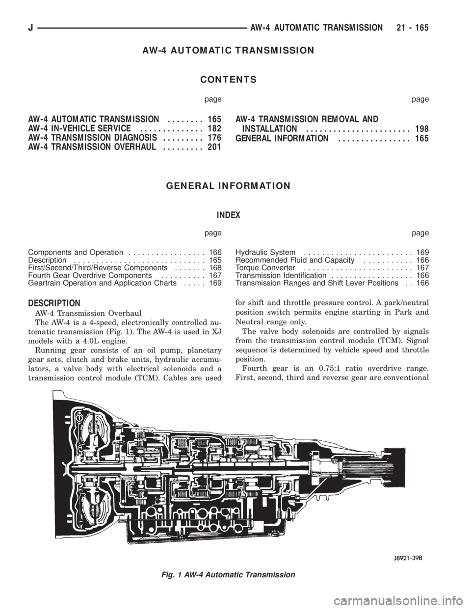
AW-4 AUTOMATIC TRANSMISSION
CONTENTS
page page
AW-4 AUTOMATIC TRANSMISSION........ 165
AW-4 IN-VEHICLE SERVICE.............. 182
AW-4 TRANSMISSION DIAGNOSIS......... 176
AW-4 TRANSMISSION OVERHAUL......... 201AW-4 TRANSMISSION REMOVAL AND
INSTALLATION....................... 198
GENERAL INFORMATION................ 165
GENERAL INFORMATION
INDEX
page page
Components and Operation................. 166
Description............................. 165
First/Second/Third/Reverse Components....... 168
Fourth Gear Overdrive Components.......... 167
Geartrain Operation and Application Charts..... 169Hydraulic System........................ 169
Recommended Fluid and Capacity........... 166
Torque Converter........................ 167
Transmission Identification.................. 166
Transmission Ranges and Shift Lever Positions . . 166
DESCRIPTION
AW-4 Transmission Overhaul
The AW-4 is a 4-speed, electronically controlled au-
tomatic transmission (Fig. 1). The AW-4 is used in XJ
models with a 4.0L engine.
Running gear consists of an oil pump, planetary
gear sets, clutch and brake units, hydraulic accumu-
lators, a valve body with electrical solenoids and a
transmission control module (TCM). Cables are usedfor shift and throttle pressure control. A park/neutral
position switch permits engine starting in Park and
Neutral range only.
The valve body solenoids are controlled by signals
from the transmission control module (TCM). Signal
sequence is determined by vehicle speed and throttle
position.
Fourth gear is an 0.75:1 ratio overdrive range.
First, second, third and reverse gear are conventional
Fig. 1 AW-4 Automatic Transmission
JAW-4 AUTOMATIC TRANSMISSION 21 - 165
Page 1740 of 2158
PRESSURE TEST ANALYSIS
If pressures in D and Reverse are higher than
specified in test, check for the following:
²throttle cable loose, worn, binding or out of adjust-
ment
²throttle valve, downshift plug, throttle cam, or pri-
mary regulator valve are sticking, worn or damaged
If pressures in D and Reverse are lower than spec-
ified in test, check for following:
²throttle cable loose, worn, binding or out of adjust-
ment
²throttle valve, downshift plug, or throttle cam
sticking, worn or damaged
²primary regulator valve sticking, worn, or dam-
aged
²oil pump gears or housing worn, or damaged
²overdrive clutch worn, or damaged
If pressures are low in D range only, check for fol-
lowing:
²forward clutch worn or damaged
²fluid leakage in D range circuit (component seal
and O-rings)
If pressures are low in Reverse only, check for fol-
lowing:
²shift cable and manual valve out of adjustment
²fluid leakage in reverse circuit (component seal
and O-rings)
²direct clutch worn or damaged
²first/reverse brake worn or damaged
TORQUE CONVERTER STALL TEST
Stall testing checks the holding ability of the trans-
mission clutches and brakes and of the torque con-
verter stator overrunning clutch.Stall speeds are
checked in both Drive and Reverse ranges with
the AW-4 transmission.
(1) Before starting test, be sure fluid level is cor-
rect and fluid is at normal operating temperature.
(2) Connect tachometer to engine. Position tachom-
eter so it can be viewed from drivers seat.
(3) Apply parking brakes and block wheels.
(4) Apply and hold service brakes.
(5) Shift transfer case into 2H position.
(6) Start engine.
WARNING: DO NOT ALLOW ANYONE TO STAND AT
THE FRONT OR REAR OF THE VEHICLE DURING
THE TEST.
(7) Shift transmission into D range.
(8) Open throttle completely and record maximum
engine rpm registered on tachometer. It takes any-
where from 4 to 10 seconds to reach maximum rpm.
However, once maximum rpm has been achieved,do
not hold wide open throttle for more than 3-4
seconds.CAUTION: Stalling the converter causes a rapid in-
crease in fluid temperature. To avoid fluid overheat-
ing, hold wide open throttle for no more than 4
seconds after reaching peak rpm. In addition, if
more than one stall test is required, run the engine
at 1000 rpm with the transmission in Neutral for at
least 20 seconds to cool the fluid.
(9) Stall speed should be in 2100-2400 rpm range
in Drive.
(10) Release throttle, shift transmission into Neu-
tral, and run engine for 20-30 seconds to cool fluid.
(11) Shift transmission into Reverse.
(12) Repeat stall test described in step (8).
(13) Stall speed in Reverse should also be in 2100-
2400 rpm range.
(14) Release accelerator pedal, shift transmission
into Neutral, and run engine for 20-30 seconds to
cool fluid.
STALL SPEED TEST ANALYSIS
If engine rpm is lower than specified in D and Re-
verse, check for the following:
²engine output/performance insufficient
²stator overrunning clutch in torque converter not
holding if engine speed was 1500 rpm or less.
If stall speed in D range is higher than specified,
check for the following:
²line pressure low
²forward clutch slipping
²No. 2 one-way clutch not holding
²overdrive one-way clutch not holding
If stall speed in Reverse was higher than specified,
check for the following:
²line pressure low
²direct clutch slipping
²first/ reverse brake slipping
²overdrive one-way clutch not holding
If stall speeds were higher than specified in both D
and Reverse, check for the following:
²low fluid level
²line pressure low
²overdrive one-way clutch not holding
TIME LAG TEST
This test checks general condition of the overdrive
clutch, forward clutch, rear clutch and first/reverse
brake. Condition is indicated by the amount of time
required for clutch/brake engagement with the en-
gine at curb idle speed. Engagement time is mea-
sured for D and Reverse positions. A stop watch is
recommended for test accuracy.
TEST PROCEDURE
(1) Check and adjust transmission fluid level if
necessary.
(2) Bring transmission to normal operating tem-
perature.
21 - 178 AW-4 TRANSMISSION DIAGNOSISJ
Page 1744 of 2158
AW-4 IN-VEHICLE SERVICE
INDEX
page page
Accumulator Pistons and Springs............. 189
Adapter Housing Seal Replacement........... 191
Checking Fluid Level and Condition........... 182
Manual Valve Shaft Seal Replacement......... 187
Park Interlock Cable Adjustment............. 195
Park Rod and Pawl Service................. 190
Park/Neutral Position Switch................ 183
Refilling After Overhaul or Fluid/Filter Change . . . 182
Second Coast Brake Servo................. 190
Shift Cable Adjustment.................... 195
Speed Sensor........................... 192Speed Sensor RotorÐSpeedometer Drive Gear . . 193
Throttle Position Sensor (TPS) Service........ 193
Transmission Control Module (TCM) Service.... 183
Transmission Cooler Line Fittings............ 197
Transmission Cooler Service................ 196
Transmission Throttle Cable Adjustment........ 194
Transmission Throttle Cable Replacement...... 193
Transmission Valve Body Installation.......... 187
Transmission Valve Body Removal........... 186
Transmission Valve Body Solenoids........... 184
CHECKING FLUID LEVEL AND CONDITION
Recommended fluid for AW-4 transmissions is Mo-
par Dexron IIE/Mercon.
Mopar Dexron II can also be used but only when
Mercon fluid is not available.
CHECKING FLUID LEVEL
(1) Be sure transmission fluid is at normal operat-
ing temperature. Normal operating temperature is
reached after approximately 15 miles (25 km) of op-
eration.
(2) Position vehicle on level surface. This is impor-
tant for an accurate fluid level check.
(3) Shift transmission through all gear ranges and
back to Park.
(4) Apply parking brakes.
(5) Verify that transmission is in Park.
(6) Wipe off dipstick handle to prevent dirt from
entering fill tube. Then remove dipstick and check
fluid level and condition.
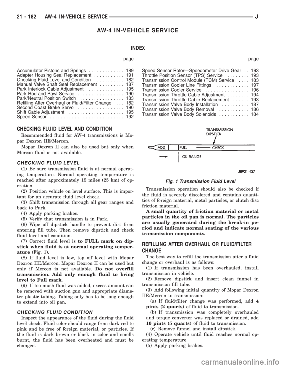
(7) Correct fluid level isto FULL mark on dip-
stick when fluid is at normal operating temper-
ature(Fig. 1).
(8) If fluid level is low, top off level with Mopar
Dexron IIE/Mercon. Mopar Dexron II can be used but
only if Mercon is not available.Do not overfill
transmission. Add only enough fluid to bring
level to Full mark.
(9) If too much fluid was added, excess amount can
be removed with suction gun and appropriate diame-
ter plastic tubing. Tubing only has to be long enough
to extend into oil pan.
CHECKING FLUID CONDITION
Inspect the appearance of the fluid during the fluid
level check. Fluid color should range from dark red to
pink and be free of foreign material, or particles. If
the fluid is dark brown or black in color and smells
burnt, the fluid has been overheated and must be
changed.Transmission operation should also be checked if
the fluid is severely discolored and contains quanti-
ties of foreign material, metal particles, or clutch disc
friction material.
A small quantity of friction material or metal
particles in the oil pan is normal. The particles
are usually generated during the break-in pe-
riod and indicate normal seating of the various
transmission components.
REFILLING AFTER OVERHAUL OR FLUID/FILTER
CHANGE
The best way to refill the transmission after a fluid
change or overhaul is as follows:
(1) If transmission has been overhauled, install
transmission in vehicle.
(2) Remove dipstick and insert clean funnel in
transmission fill tube.
(3) Add following initial quantity of Mopar Dexron
IIE/Mercon to transmission:
(a) If fluid/filter change was performed, add4
pints (2 quarts)of fluid to transmission.
(b) If transmission was completely overhauled
and torque converter was replaced or drained, add
10 pints (5 quarts)of fluid to transmission.
(c) Remove funnel and install dipstick.
(4) Operate vehicle until fluid reaches normal op-
erating temperature.
(5) Apply parking brakes.
Fig. 1 Transmission Fluid Level
21 - 182 AW-4 IN-VEHICLE SERVICEJ
Page 1856 of 2158
OVERHAUL CLEANING AND INSPECTION
Clean the transfer case components thoroughly
with solvent. Remove all traces of sealer from the
case and retainer seal surfaces.
Clean the oil pickup screen with solvent. Shake ex-
cess solvent from screen and allow it air dry. Use
compressed air to remove solvent residue from all oil
feed passages and channels in the case halves.
Inspect the splines and bearing surfaces on the
both shafts. Replace either shaft as necessary if wear,
or damage is evident.
Check condition of the shift forks, fork pads and
shift rail. Minor scratches/nicks on the rail can be
smoothed with 320/400 grit emery cloth. Replace the
mode fork pads if worn. Replace the range fork if the
pads are worn, missing, or damaged.
On synchro equipped models, inspect the synchro
sleeve, hub, struts, springs, and the stop ring. Re-
place worn, or damaged parts as necessary.
Do not attempt to salvage and reuse snap rings
that were bent, or distorted. It is recommended that
all snap rings be replaced during overhaul.Replace the front yoke nut as it should not be re-
used. Also replace the rubber seal if worn, cut, or
torn.
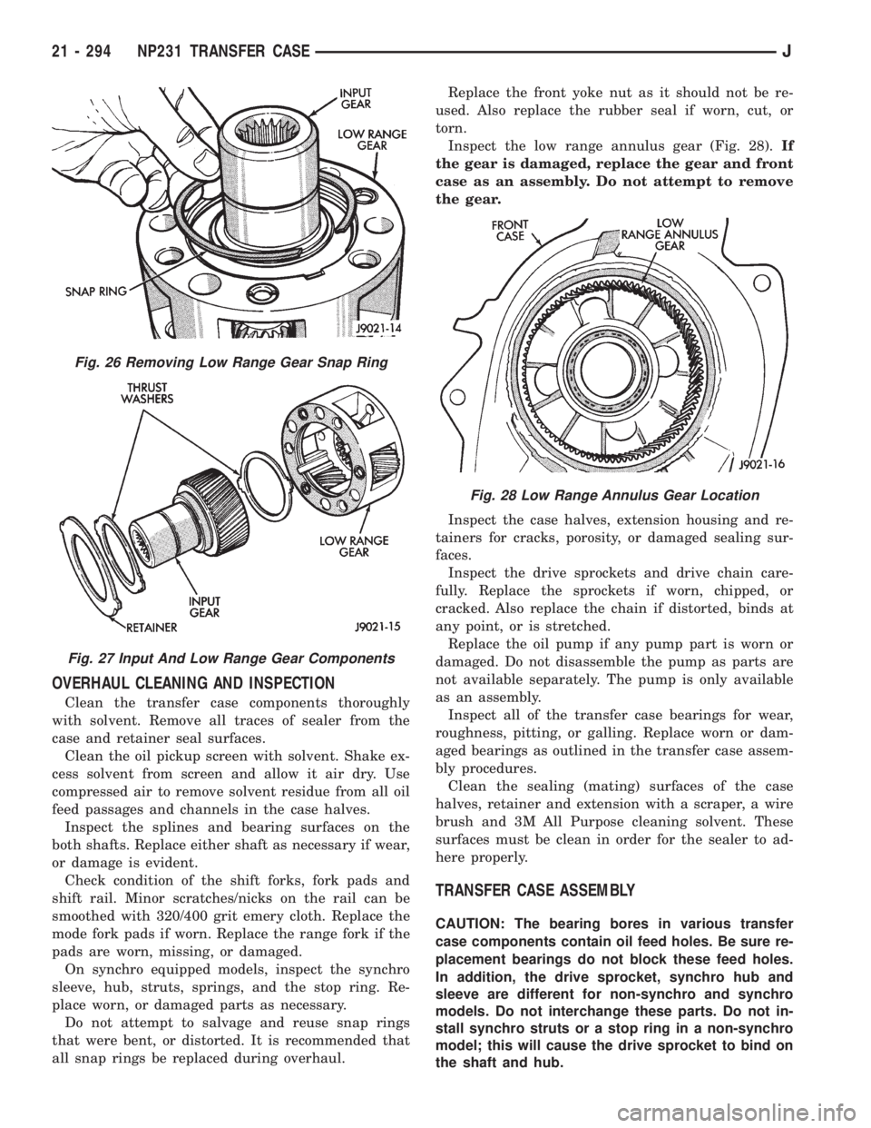
Inspect the low range annulus gear (Fig. 28).If
the gear is damaged, replace the gear and front
case as an assembly. Do not attempt to remove
the gear.
Inspect the case halves, extension housing and re-
tainers for cracks, porosity, or damaged sealing sur-
faces.
Inspect the drive sprockets and drive chain care-
fully. Replace the sprockets if worn, chipped, or
cracked. Also replace the chain if distorted, binds at
any point, or is stretched.
Replace the oil pump if any pump part is worn or
damaged. Do not disassemble the pump as parts are
not available separately. The pump is only available
as an assembly.
Inspect all of the transfer case bearings for wear,
roughness, pitting, or galling. Replace worn or dam-
aged bearings as outlined in the transfer case assem-
bly procedures.
Clean the sealing (mating) surfaces of the case
halves, retainer and extension with a scraper, a wire
brush and 3M All Purpose cleaning solvent. These
surfaces must be clean in order for the sealer to ad-
here properly.
TRANSFER CASE ASSEMBLY
CAUTION: The bearing bores in various transfer
case components contain oil feed holes. Be sure re-
placement bearings do not block these feed holes.
In addition, the drive sprocket, synchro hub and
sleeve are different for non-synchro and synchro
models. Do not interchange these parts. Do not in-
stall synchro struts or a stop ring in a non-synchro
model; this will cause the drive sprocket to bind on
the shaft and hub.
Fig. 26 Removing Low Range Gear Snap Ring
Fig. 27 Input And Low Range Gear Components
Fig. 28 Low Range Annulus Gear Location
21 - 294 NP231 TRANSFER CASEJ
Page 1881 of 2158
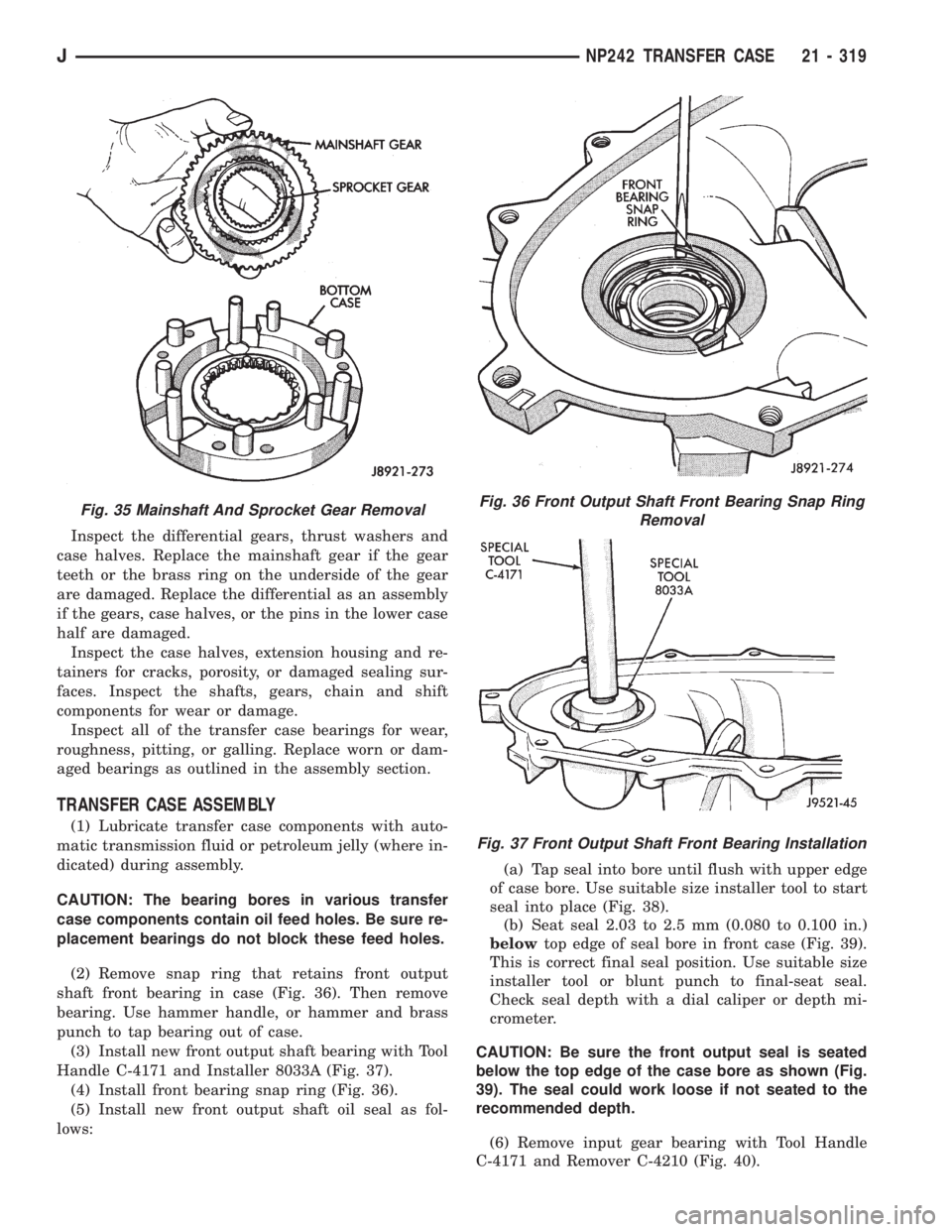
Inspect the differential gears, thrust washers and
case halves. Replace the mainshaft gear if the gear
teeth or the brass ring on the underside of the gear
are damaged. Replace the differential as an assembly
if the gears, case halves, or the pins in the lower case
half are damaged.
Inspect the case halves, extension housing and re-
tainers for cracks, porosity, or damaged sealing sur-
faces. Inspect the shafts, gears, chain and shift
components for wear or damage.
Inspect all of the transfer case bearings for wear,
roughness, pitting, or galling. Replace worn or dam-
aged bearings as outlined in the assembly section.
TRANSFER CASE ASSEMBLY
(1) Lubricate transfer case components with auto-
matic transmission fluid or petroleum jelly (where in-
dicated) during assembly.
CAUTION: The bearing bores in various transfer
case components contain oil feed holes. Be sure re-
placement bearings do not block these feed holes.
(2) Remove snap ring that retains front output
shaft front bearing in case (Fig. 36). Then remove
bearing. Use hammer handle, or hammer and brass
punch to tap bearing out of case.
(3) Install new front output shaft bearing with Tool
Handle C-4171 and Installer 8033A (Fig. 37).
(4) Install front bearing snap ring (Fig. 36).
(5) Install new front output shaft oil seal as fol-
lows:(a) Tap seal into bore until flush with upper edge
of case bore. Use suitable size installer tool to start
seal into place (Fig. 38).
(b) Seat seal 2.03 to 2.5 mm (0.080 to 0.100 in.)
belowtop edge of seal bore in front case (Fig. 39).
This is correct final seal position. Use suitable size
installer tool or blunt punch to final-seat seal.
Check seal depth with a dial caliper or depth mi-
crometer.
CAUTION: Be sure the front output seal is seated
below the top edge of the case bore as shown (Fig.
39). The seal could work loose if not seated to the
recommended depth.
(6) Remove input gear bearing with Tool Handle
C-4171 and Remover C-4210 (Fig. 40).
Fig. 35 Mainshaft And Sprocket Gear RemovalFig. 36 Front Output Shaft Front Bearing Snap Ring
Removal
Fig. 37 Front Output Shaft Front Bearing Installation
JNP242 TRANSFER CASE 21 - 319
Page 1912 of 2158
WHEELS
GENERAL INFORMATION
Original equipment wheels are designed for the
specified Maximum Vehicle Capacity.
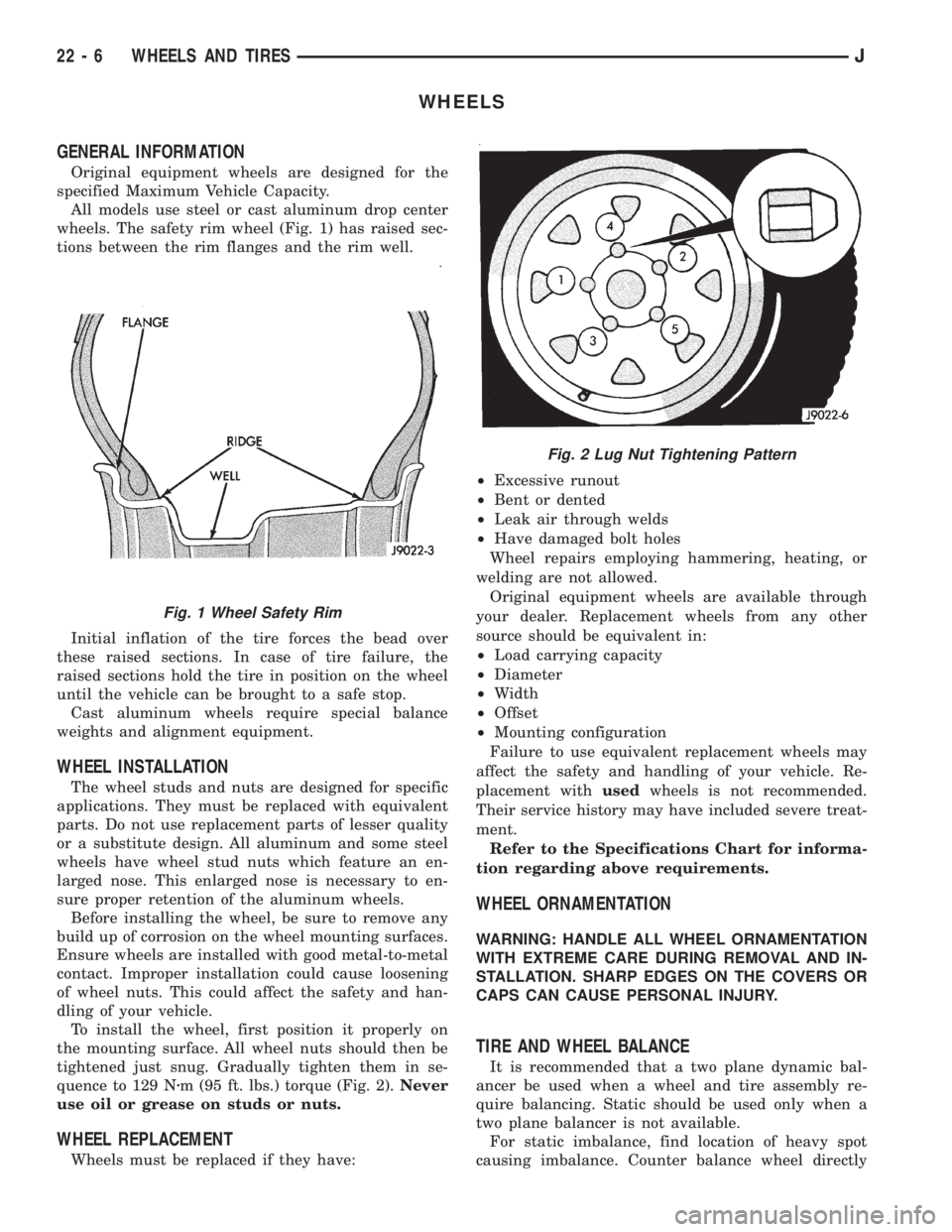
All models use steel or cast aluminum drop center
wheels. The safety rim wheel (Fig. 1) has raised sec-
tions between the rim flanges and the rim well.
Initial inflation of the tire forces the bead over
these raised sections. In case of tire failure, the
raised sections hold the tire in position on the wheel
until the vehicle can be brought to a safe stop.
Cast aluminum wheels require special balance
weights and alignment equipment.
WHEEL INSTALLATION
The wheel studs and nuts are designed for specific
applications. They must be replaced with equivalent
parts. Do not use replacement parts of lesser quality
or a substitute design. All aluminum and some steel
wheels have wheel stud nuts which feature an en-
larged nose. This enlarged nose is necessary to en-
sure proper retention of the aluminum wheels.
Before installing the wheel, be sure to remove any
build up of corrosion on the wheel mounting surfaces.
Ensure wheels are installed with good metal-to-metal
contact. Improper installation could cause loosening
of wheel nuts. This could affect the safety and han-
dling of your vehicle.
To install the wheel, first position it properly on
the mounting surface. All wheel nuts should then be
tightened just snug. Gradually tighten them in se-
quence to 129 Nzm (95 ft. lbs.) torque (Fig. 2).Never
use oil or grease on studs or nuts.
WHEEL REPLACEMENT
Wheels must be replaced if they have:²Excessive runout
²Bent or dented
²Leak air through welds
²Have damaged bolt holes
Wheel repairs employing hammering, heating, or
welding are not allowed.
Original equipment wheels are available through
your dealer. Replacement wheels from any other
source should be equivalent in:
²Load carrying capacity
²Diameter
²Width
²Offset
²Mounting configuration
Failure to use equivalent replacement wheels may
affect the safety and handling of your vehicle. Re-
placement withusedwheels is not recommended.
Their service history may have included severe treat-
ment.
Refer to the Specifications Chart for informa-
tion regarding above requirements.
WHEEL ORNAMENTATION
WARNING: HANDLE ALL WHEEL ORNAMENTATION
WITH EXTREME CARE DURING REMOVAL AND IN-
STALLATION. SHARP EDGES ON THE COVERS OR
CAPS CAN CAUSE PERSONAL INJURY.
TIRE AND WHEEL BALANCE
It is recommended that a two plane dynamic bal-
ancer be used when a wheel and tire assembly re-
quire balancing. Static should be used only when a
two plane balancer is not available.
For static imbalance, find location of heavy spot
causing imbalance. Counter balance wheel directly
Fig. 1 Wheel Safety Rim
Fig. 2 Lug Nut Tightening Pattern
22 - 6 WHEELS AND TIRESJ
Page 2090 of 2158
oil until you are ready to use it. Install the cap im-
mediately after using. Store the oil only in a clean
moisture-free container.
Keep service tools and the work area clean. Con-
tamination of A/C system through careless work hab-
its must be avoided.
COOLING SYSTEM
To maintain the performance level of the heating/
air conditioning system, the engine cooling system
must be properly maintained.
The use of a bug screen is not recommended. Any
obstructions in front of the radiator or condenser can
reduce the performance of the A/C and cooling sys-
tem. If a bug screen is used it must be cleaned fre-
quently.
COOLANT PRECAUTIONS
WARNING: ANTIFREEZE IS AN ETHYLENE GLYCOL
BASE COOLANT AND IS HARMFUL IF SWAL-
LOWED OR INHALED. IF SWALLOWED, DRINK
TWO GLASSES OF WATER AND INDUCE VOMIT-
ING. IF INHALED, MOVE TO FRESH AIR AREA.
SEEK MEDICAL ATTENTION IMMEDIATELY.
WARNING: WASH SKIN AND CLOTHING THOR-
OUGHLY AFTER COMING IN CONTACT WITH ETH-
YLENE GLYCOL.
WARNING: KEEP OUT OF REACH OF CHILDREN
AND PETS.
WARNING: DO NOT OPEN A COOLING SYSTEM
WHEN THE ENGINE IS AT RUNNING TEMPERA-
TURE. PERSONAL INJURY CAN RESULT.WARNING: DO NOT STORE IN OPEN OR UN-
MARKED CONTAINERS.
WARNING: HOT ENGINE COOLANT CAN CAUSE
SEVERE BURNS. DO NOT OPEN THE RADIATOR
DRAIN COCK WHEN THE COOLING SYSTEM IS
HOT AND PRESSURIZED. ALLOW THE COOLANT
TO DECREASE TO ROOM TEMPERATURE BEFORE
STARTING REPAIR OPERATIONS.
The engine cooling system is designed to develop
internal pressure of 97 to 124 kPa (14 to 18 psi). Al-
low the vehicle 15 minutes to cool down (or until a
safe temperature and pressure are attained) before
opening the cooling system. Refer to Group 7, Cooling
System.REFRIGERANT HOSES/TUBES PRECAUTIONS
Kinks or sharp bends in the refrigerant tubing or
hoses will reduce the capacity of the entire system.
High pressures are produced in the system when it is
operating. Extreme care must be exercised to make
sure that all connections are pressure tight. Dirt and
moisture can enter the system when it is opened for
repair.
A good rule for the flexible hose lines is to keep the
radius of all bends at least 10 times the diameter of
the hose. Sharp bends will reduce the flow of refrig-
erant. The flexible hose lines should be routed so
they are at least 80 mm (3 inches) from the exhaust
manifold. It is a good practice to inspect all flexible
hose lines at least once a year to make sure they are
in good condition and properly routed.
24 - 10 HEATING AND AIR CONDITIONINGJ
Page 2134 of 2158
ENTRY MODULE REMOVE/INSTALL,
KEYLESS...........................8P-10
ENTRY RECEIVER, KEYLESS.............8C-1
ENTRY RECEIVERÐXJ, KEYLESS........23-93
ENTRY TRANSMITTER, KEYLESS . 8P-1,8P-7,8P-8
EQUIPMENT, REFRIGERANT.............24-7
EQUIVALENT VALUES, CONVERSION
FORMULAS.......................Intro.-11
EVACUATING REFRIGERANT SYSTEM.....24-11
EVAP CANISTER..................25-4,25-7
EVAP (EVAPORATION) CONTROL
SYSTEM............................25-4
EVAPORATIVE HOUSING
COMPONENTSÐYJ....................24-6
EVAPORATOR AND HOUSING...........24-35
EVAPORATOR COIL...................24-30
EVAPORATOR/BLOWER HOUSING........24-29
EXHAUST GAS RECIRCULATION (EGR)
SYSTEM............................25-1
EXHAUST GRILLEÐXJ, AIR............23-25
EXHAUST HEAT SHIELDS...............11-1
EXHAUST MANIFOLDÐ2.5L ENGINE,
ENGINE.............................11-7
EXHAUST MANIFOLDÐ4.0L ENGINE,
ENGINE.............................11-7
EXHAUST PIPEÐXJ VEHICLES...........11-3
EXHAUST PIPEÐYJ VEHICLES...........11-4
EXHAUST SYSTEM; EXHAUST SYSTEM
AND INTAKE MANIFOLD................11-1
EXHAUST SYSTEM; LUBRICATION AND
MAINTENANCE.......................0-21
EXHAUST SYSTEM DIAGNOSIS..........11-2
EXHAUST TAILPIPEÐXJ VEHICLES,
MUFFLER............................11-5
EXHAUST TAILPIPEÐYJ VEHICLES,
MUFFLER............................11-6
EXPANSION VALVE..............24-31,24-35
EXTENDED IDLE SWITCH; FUEL/
IGNITION (XJ).....................8W-30-5
EXTENDED IDLE SWITCH TEST..........14-48
EXTENDED IDLE SWITCHÐPCM INPUT . . . 14-23
EXTENSIONÐXJ, QUARTER TRIM PANEL . 23-87
EXTERIOR COMPONENTS.........23-104,23-3
EXTERIOR LAMPSÐXJ................8L-18
EXTERIOR LAMPSÐYJ................8L-32
EXTERIOR MOLDINGSÐXJ, DOOR
WINDOW...........................23-54
EXTERIOR NAMEPLATES (ADHESIVE-
BACKED)ÐYJ......................23-120
EXTERIOR NAMEPLATESÐXJ...........23-26
EXTERNAL HANDLEÐXJ, DOOR.........23-48
EXTERNAL MIRRORSÐXJ.............23-27
EXTERNAL RELEASE HANDLEÐYJ,
FULL-METAL DOOR LATCH............23-140
EXTERNAL SPARE/WHEEL TIRE
CARRIERÐYJ......................23-133
(EXTERNAL)ÐYJ, HALF METAL DOOR
MIRROR..........................23-121
EYE BUSHING REPLACEMENT, LEAF
SPRING; FRONT SUSPENSION AND
AXLE...............................2-17
EYE BUSHING REPLACEMENT, LEAF
SPRING; REAR SUSPENSION AND
AXLES............................3-5,3-7
FAN RELAY AND MOTOR, RADIATOR;
AIR CONDITIONING/HEATER (XJ)......8W-42-2
FAN RELAY AND MOTOR, RADIATOR;
AIR CONDITIONING/HEATER (XJ-RHD) . . 8W-42-2
FAN RELAYÐPCM OUTPUT, RADIATOR . . . 14-28
FANÐXJ MODELS WITH 4.0L
6-CYLINDER ENGINE, AUXILIARY
ELECTRIC COOLING...................7-35
FANS, COOLING SYSTEM...............7-32
FEED, BATTERY; FUEL/IGNITION (XJ) . . . 8W-30-1
FEED, BATTERY; FUEL/IGNITION (YJ) . . . 8W-30-2
FEED, BATTERY; FUEL/IGNITION
(XJ-RHD).........................8W-30-1
FEED, IGNITION; FUEL/IGNITION
(XJ-RHD).........................8W-30-1
FENDER FLAREÐYJ.................23-114
FENDER INNER SPLASH SHIELDSÐYJ . . 23-116
FENDER SPLASH APRONSÐYJ........23-115
FENDERÐXJ, FRONT
.................23-14
FENDERSÐYJ
......................23-110
FIELDÐPCM OUTPUT, GENERATOR
......14-27
FILL LEVEL, TRANSFER CASE
LUBRICANT
........................21-284
FILLER DOOR BUMPERSÐXJ, FUEL
.....23-27FILLER HOSE SPLASH SHIELDÐXJ
VEHICLES, FUEL......................13-4
FILLER NOZZLE/TUBEÐXJ, FUEL........23-26
FILLER PROTECTOR/NOZZLEÐYJ, FUEL . 23-121
FILLER TUBE CAP, FUEL TANK;
EMISSION CONTROL SYSTEMS......25-4,25-7
FILLER TUBE CAP, FUEL TANK; FUEL
SYSTEM............................14-13
FILLER TUBE, NO-LEAD FUEL TANK......14-13
FILTER DRIERÐ2.5L ENGINES,
CONDENSER........................24-27
FILTER DRIERÐ4.0L ENGINES..........24-28
FILTER, ENGINE OIL...................0-17
FILTER, FUEL; FUEL SYSTEM.......14-60,14-9
FILTER, FUEL; LUBRICATION AND
MAINTENANCE.......................0-19
FILTER REPLACEMENT, ENGINE OIL
CHANGE............................0-16
FILTER REPLACEMENT, FLUID..........21-99
FILTER REPLACEMENT, OIL............21-103
FIN SENSING CYCLING CLUTCH SWITCH . 24-15,
24-31
FINAL ASSEMBLY; FRONT SUSPENSION
AND AXLE...........................2-46
FINAL ASSEMBLY; REAR SUSPENSION
AND AXLES..........................3-29
FIRING ORDERÐ2.5L 4-CYLINDER
ENGINE, ENGINE.....................8D-32
FIRING ORDERÐ4.0L 6-CYLINDER
ENGINE, ENGINE.....................8D-32
FIRST-REVERSE BRAKE PISTON AND
TRANSMISSION CASE OVERHAUL......21-247
FIRST/SECOND/THIRD/REVERSE
COMPONENTS......................21-168
FITTING CHART, CONNECTING ROD
BEARING........................9-41,9-83
FITTING CHART, MAIN BEARING......9-48,9-90
FITTING O-RING SEAL, FLOW CONTROL
VALVE .............................19-14
FITTING SERVICE, TRANSMISSION
COOLER LINE......................21-111
FITTINGS, TRANSMISSION COOLER LINE . 21-197
FLAREÐYJ, FENDER.................23-114
FLARES AND LINERSÐXJ, REAR
WHEELHOUSE.......................23-19
FLASHER, COMBINATION; TURN
SIGNALS (XJ).....................8W-52-1
FLASHERS, HAZARD; TURN SIGNALS
(XJ).............................8W-52-1
FLASHERS, HAZARD; TURN SIGNALS
(XJ-RHD).........................8W-52-1
FLASHERS, HAZARD; TURN SIGNALS
(YJ).............................8W-52-1
FLOOR BRACKETSÐXJ, SPARE
TIRE/WHEEL HOLDDOWN..............23-98
FLOOR CONSOLEÐXJ, FULL...........23-95
FLOOR CONSOLESÐYJ...............23-155
FLOOR MATSÐXJ, CARPETS...........23-99
FLOOR SHIFTÐXJ, MINI-CONSOLE WITH . 23-94
FLOW CONTROL VALVE FITTING O-RING
SEAL..............................19-14
FLOW TESTING, TRANSMISSION
COOLER...........................21-113
FLUID AND FILTER REPLACEMENT.......21-99
FLUID CAPACITIES.....................0-3
FLUID, CLUTCH LINKAGE................6-1
FLUID CONTAMINATION, BRAKE.......5-10,5-7
FLUID LEVEL AND CONDITION,
CHECKING.........................21-182
FLUID LEVEL, BRAKE..................5-10
FLUID LEVEL CHECK.............21-70,21-99
FLUID LEVEL, CLUTCH.................6-14
FLUID, RECOMMENDED BRAKE..........5-10
FLUID WARNING LAMP, LOW WASHER;
INSTRUMENT CLUSTER (XJ).........8W-40-2
FLUID WARNING LAMP, LOW WASHER;
INSTRUMENT CLUSTER (XJ-RHD).....8W-40-2
FLUID/FILTER CHANGE, REFILLING
AFTER OVERHAUL OR..........21-100,21-182
FLUID/LUBRICANTS/CLEANING
SOLVENTS, BRAKE
.....................5-2
FLUIDÐBRAKE BLEEDINGÐ
BRAKELINES AND HOSES, BRAKE
........5-10
FLUSHING, COOLING SYSTEM
CLEANING/REVERSE
...................7-22
FLUSHING, TRANSMISSION COOLER
REVERSE
..........................21-114
FLYWHEEL RUNOUT
....................6-3FLYWHEEL SERVICE...................6-16
FOG LAMP DIAGNOSIS............8L-21,8L-3
FOG LAMP REPLACEMENTÐXJ..........8L-9
FOG LAMP REPLACEMENTÐYJ.........8L-25
FOG LAMP SWITCH REPLACEMENTÐXJ . . 8L-10
FOG LAMP SWITCH REPLACEMENTÐYJ . . 8L-26
FOG LAMPS; FRONT LIGHTING (XJ) . . . 8W-50-1
FOG LAMPS; FRONT LIGHTING (XJ-RHD) . 8W-50-2
FOG LAMPS; FRONT LIGHTING (YJ) . . . 8W-50-1
FOG LAMPSÐXJ......................8L-7
FOG LAMPSÐYJ.....................8L-23
FORM-IN-PLACE GASKETS...............9-1
FORMULAS AND EQUIVALENT VALUES,
CONVERSION.....................Intro.-11
FORWARD CLUTCH OVERHAUL........21-232
FOURTH GEAR OVERDRIVE
COMPONENTS......................21-167
FOUR-WHEEL DRIVE (4WD) SWITCH;
INSTRUMENT CLUSTER (XJ-RHD).....8W-40-2
FOUR-WHEEL DRIVE (4WD) SWITCH;
TRANSMISSION CONTROLS (XJ-RHD) . . 8W-31-1
FOUR-WHEEL-DRIVE VEHICLE TOWING....0-12
FRAME.........................13-10,13-1
FRAME CROSSMEMBER COVER.........13-16
FRAME DIMENSIONS.............13-13,13-1
FRAME GLASS CHANNEL
REPLACEMENTÐYJ, DOOR...........23-142
FRAME REPAIRS......................13-13
FRAME STRAIGHTENING...............13-13
FRAME WEATHERSTRIP SEALÐYJ,
WINDSHIELD.......................23-146
FRAMEÐXJ, BUCKET SEATBACK COVER . . 23-81
FRAMEÐYJ, WINDSHIELD............23-145
FREQUENCY INTERFERENCE, RADIO......8F-5
FRESH AIR DOOR VACUUM MOTOR......24-34
FRESH AIR INTAKE DUCT..............24-34
FRONT AND REAR AXLES...............0-24
FRONT AXLE, MODEL 30...............2-49
FRONT BUCKET SEATSÐXJ............23-81
FRONT BUMPER.................13-16,13-5
FRONT CABLE REPLACEMENT (YJ),
PARKING BRAKE......................5-67
FRONT CARPET/MATÐXJ..............23-99
FRONT CLUTCH OVERHAUL...........21-134
FRONT DOOR SPACER BLOCKSÐTWO-
DOOR VEHICLES.....................23-53
FRONT DOOR WINDOW GLASS
REGULATORÐXJ....................23-42
FRONT DOOR WINDOW GLASSÐXJ.....23-43
FRONT DRIVE AXLE....................2-3
FRONT FENDERÐXJ..................23-14
FRONT INNER SCUFF PLATE/COWL SIDE
TRIM PANELÐXJ....................23-86
FRONT PARK/TURN SIGNAL LAMP BULB
REPLACEMENTÐXJ...................8L-9
FRONT PARK/TURN SIGNAL LAMP BULB
REPLACEMENTÐYJ..................8L-25
FRONT PLANETARY GEAR OVERHAUL . . . 21-237
FRONT SERVO AND BAND OVERHAUL . . . 21-146
FRONT SHOULDER BELT/BUCKLEÐXJ....23-90
FRONT SHOULDER BELTSÐYJ.........23-154
FRONT SKID PLATE
....................13-1
FRONT SUSPENSION
...................2-1
FRONT SUSPENSION COMPONENTS, XJ
. . . 2-49
FRONT SUSPENSION COMPONENTS, YJ
. . . 2-49
FRONT SUSPENSION, XJ
...............2-11
FRONT SUSPENSION, YJ
...............2-15
FRONT TOW HOOKS
...................13-7
FRONT WHEEL ALIGNMENT
..............2-5
FRONT WHEEL BEARINGS
..............0-28
FRONT WHEEL SENSOR INSTALLATION
....5-38
FRONT WHEEL SENSOR REMOVAL
.......5-38
FUEL DELIVERY SYSTEM
...............14-3
FUEL FILLER DOOR BUMPERSÐXJ
......23-27
FUEL FILLER HOSE SPLASH SHIELDÐXJ
VEHICLES
...........................13-4
FUEL FILLER NOZZLE/TUBEÐXJ
........23-26
FUEL FILLER PROTECTOR/NOZZLEÐYJ
. . 23-121
FUEL FILTER; FUEL SYSTEM
........14-60,14-9
FUEL FILTER; LUBRICATION AND
MAINTENANCE
.......................0-19
FUEL GAUGE; INSTRUMENT CLUSTER
(XJ)
.............................8W-40-1
FUEL GAUGE; INSTRUMENT CLUSTER
(XJ-RHD)
.........................8W-40-1
FUEL GAUGE SENDING UNIT
...........14-16
10 INDEXJ
Description Group-Page Description Group-Page Description Group-Page