1995 JEEP YJ oil
[x] Cancel search: oilPage 63 of 2158
XJ FRONT SUSPENSION
INDEX
page page
Axle Bushing Replacement.................. 12
Coil Spring.............................. 14
Lower Suspension Arm..................... 13
Service Information........................ 11
Shock Absorber.......................... 13Spring and Shock Diagnosis................. 13
Stabilizer Bar............................ 11
Track Bar............................... 11
Upper Suspension Arm..................... 12
SERVICE INFORMATION
Periodic lubrication of the steering system and sus-
pension components is required. Refer to Group 0,
Lubrication And Maintenance for the service inter-
val.
CAUTION: Suspension components with rubber
bushings should be tightened with the vehicle at
normal height. It is important to have the springs
supporting the weight of the vehicle when the fas-
teners are torqued. If springs are not at their normal
ride position, vehicle ride comfort could be affected
and premature bushing wear may occur. Rubber
bushings must never be lubricated.
TRACK BAR
REMOVAL
(1) Raise and support the vehicle.
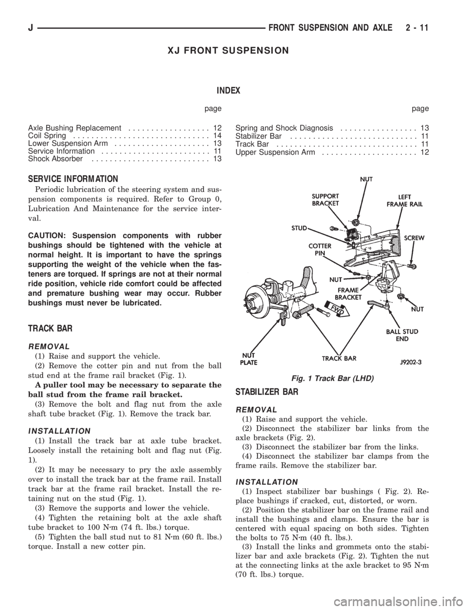
(2) Remove the cotter pin and nut from the ball
stud end at the frame rail bracket (Fig. 1).
A puller tool may be necessary to separate the
ball stud from the frame rail bracket.
(3) Remove the bolt and flag nut from the axle
shaft tube bracket (Fig. 1). Remove the track bar.
INSTALLATION
(1) Install the track bar at axle tube bracket.
Loosely install the retaining bolt and flag nut (Fig.
1).
(2) It may be necessary to pry the axle assembly
over to install the track bar at the frame rail. Install
track bar at the frame rail bracket. Install the re-
taining nut on the stud (Fig. 1).
(3) Remove the supports and lower the vehicle.
(4) Tighten the retaining bolt at the axle shaft
tube bracket to 100 Nzm (74 ft. lbs.) torque.
(5) Tighten the ball stud nut to 81 Nzm (60 ft. lbs.)
torque. Install a new cotter pin.
STABILIZER BAR
REMOVAL
(1) Raise and support the vehicle.
(2) Disconnect the stabilizer bar links from the
axle brackets (Fig. 2).
(3) Disconnect the stabilizer bar from the links.
(4) Disconnect the stabilizer bar clamps from the
frame rails. Remove the stabilizer bar.
INSTALLATION
(1) Inspect stabilizer bar bushings ( Fig. 2). Re-
place bushings if cracked, cut, distorted, or worn.
(2) Position the stabilizer bar on the frame rail and
install the bushings and clamps. Ensure the bar is
centered with equal spacing on both sides. Tighten
the bolts to 75 Nzm (40 ft. lbs.).
(3) Install the links and grommets onto the stabi-
lizer bar and axle brackets (Fig. 2). Tighten the nut
at the connecting links at the axle bracket to 95 Nzm
(70 ft. lbs.) torque.
Fig. 1 Track Bar (LHD)
JFRONT SUSPENSION AND AXLE 2 - 11
Page 65 of 2158
LOWER SUSPENSION ARM
REMOVAL
(1) Raise and support the vehicle.
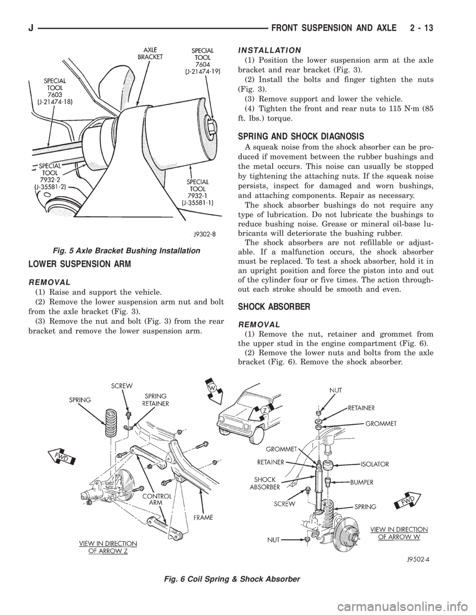
(2) Remove the lower suspension arm nut and bolt
from the axle bracket (Fig. 3).
(3) Remove the nut and bolt (Fig. 3) from the rear
bracket and remove the lower suspension arm.
INSTALLATION
(1) Position the lower suspension arm at the axle
bracket and rear bracket (Fig. 3).
(2) Install the bolts and finger tighten the nuts
(Fig. 3).
(3) Remove support and lower the vehicle.
(4) Tighten the front and rear nuts to 115 Nzm (85
ft. lbs.) torque.
SPRING AND SHOCK DIAGNOSIS
A squeak noise from the shock absorber can be pro-
duced if movement between the rubber bushings and
the metal occurs. This noise can usually be stopped
by tightening the attaching nuts. If the squeak noise
persists, inspect for damaged and worn bushings,
and attaching components. Repair as necessary.
The shock absorber bushings do not require any
type of lubrication. Do not lubricate the bushings to
reduce bushing noise. Grease or mineral oil-base lu-
bricants will deteriorate the bushing rubber.
The shock absorbers are not refillable or adjust-
able. If a malfunction occurs, the shock absorber
must be replaced. To test a shock absorber, hold it in
an upright position and force the piston into and out
of the cylinder four or five times. The action through-
out each stroke should be smooth and even.
SHOCK ABSORBER
REMOVAL
(1) Remove the nut, retainer and grommet from
the upper stud in the engine compartment (Fig. 6).
(2) Remove the lower nuts and bolts from the axle
bracket (Fig. 6). Remove the shock absorber.
Fig. 6 Coil Spring & Shock Absorber
Fig. 5 Axle Bracket Bushing Installation
JFRONT SUSPENSION AND AXLE 2 - 13
Page 66 of 2158

INSTALLATION
(1) Position the lower retainer and grommet on the
upper stud. Insert the shock absorber through the
shock tower hole.
(2) Install the lower bolts and nuts. Tighten nuts
to 23 Nzm (17 ft. lbs.) torque.
(3) Install the upper grommet and retainer on the
stud in the engine compartment. Install the nut and
tighten to 10 Nzm (8 ft. lbs.) torque.
COIL SPRING
REMOVAL
(1) Raise and support the vehicle. Position a hy-
draulic jack under the axle to support it.
(2) Remove the wheel if necessary.
(3) Mark and disconnect the front propeller shaft
from the axle.
(4) Disconnect the lower suspension arms from the
axle (Fig. 6).
(5) Disconnect the stabilizer bar link and shock ab-
sorber from the axle.
(6) Disconnect the track bar from the frame rail
bracket.(7) Disconnect the drag link from the pitman arm.
(8) Lower the axle until the spring is free from the
upper mount. Remove the coil spring clip (Fig. 6) and
remove the spring.
(9) Pull jounce bumper out of mount.
INSTALLATION
(1) Install jounce bumper into mount.
(2) Position the coil spring on the axle pad. Install
the spring clip and bolt (Fig. 6). Tighten bolt to 21
Nzm (16 ft. lbs.) torque.
(3) Raise the axle into position until the spring
seats in the upper mount.
(4) Connect the stabilizer bar links and shock ab-
sorbers to the axle bracket. Connect the track bar to
the frame rail bracket.
(5) Install the lower suspension arms to the axle.
DO NOT TIGHTEN AT THIS TIME.
(6) Install the front propeller shaft to the axle.
(7) Remove the supports and lower the vehicle.
(8) Tighten lower suspension arms nuts to 115 Nzm
(85 ft. lbs.) torque.
2 - 14 FRONT SUSPENSION AND AXLEJ
Page 68 of 2158

The shock absorber bushings do not require any
type of lubrication. Do not lubricate the bushings to
reduce bushing noise. Grease or mineral oil-base lu-
bricants will deteriorate the bushing rubber.
The shock absorbers are not refillable or adjustable.
If a malfunction occurs, the shock absorber must be
replaced. To test a shock absorber, hold it in an up-
right position and force the piston into and out of the
cylinder four or five times. The action throughout
each stroke should be smooth and even.
SHOCK ABSORBER
REMOVAL
(1) Remove the nut, retainer and grommet from the
upper stud on the frame bracket (Fig. 3).
(2) Raise and support the vehicle.
(3) Remove the nut, washers and bolt from the
shock absorber lower eye (Fig.3).
(4) Remove the shock absorber.
(5) Remove the remaining grommet and retainer
from the shock absorber stud.
INSTALLATION
(1) Position the lower retainer and grommet on the
upper stud. Insert the shock absorber through the
shock tower hole.
(2) Install the lower bolts and nuts. Tighten the
nuts to 61 Nzm (45 ft. lbs.) torque.
(3) Install the upper grommet and retainer on the
stud on the frame bracket. Install the nut and tighten
to 12 Nzm (9 ft. lbs.) torque.
LEAF SPRING
REMOVAL
(1) Raise the vehicle.
(2) Support the vehicle with jack stands placed un-
der the frame.
(3) Position a hydraulic jack under the axle. Raise
the axle to relieve the axle weight from the springs.
(4) Remove the stabilizer bar links attaching nut.
(5) Remove the nuts, the U-bolts and spring
bracket from the axle.
(6) Remove the nut and bolt that attaches the
spring front eye to the shackle (Fig. 3).
(7) Remove the nut and bolt from the spring rear
eye.
(8) Remove the spring from the vehicle.
The spring can be disassembled by removing
the spring clips and the center bolt. If the
spring bushings require replacement, refer to
the bushing removal and installation proce-
dures.
INSTALLATION
(1) Position the spring front eye in the shackle.
Loosely install the attaching bolt and nut. Do not
tighten at this time.
(2) Position the rear eye in the hanger bracket.
Loosely install the attaching bolt and nut (Fig. 3). Do
not tighten at this time.
(3) Position the axle. Install the spring bracket,
U-bolts and nuts (Fig. 3). Tighten the U-bolt nuts to
122 Nzm (90 ft. lbs.) torque.
(4) Attach the stabilizer bar links.
(5) Remove the hydraulic jack.
Fig. 2 Stabilizer BarFig. 3 Spring & Shock Absorber
2 - 16 FRONT SUSPENSION AND AXLEJ
Page 74 of 2158

MODEL 30 AXLE AND TUBE AXLE (2WD)
INDEX
page page
Axle Bushing Replacement.................. 34
Axle ShaftÐCardan U-Joint.................. 26
Backlash and Contact Pattern Analysis......... 45
Cleaning/Inspection........................ 37
Differential and Pinion Measurement........... 40
Differential Assembly....................... 38
Differential Disassembly.................... 35
Differential Installation...................... 44
Differential Removal....................... 34
Differential Shim Pack Measurement and
Adjustment............................ 43
Drive Axle Assembly ReplacementÐXJ Vehicles . . 23
Drive Axle Assembly ReplacementÐYJ Vehicles . . 24Final Assembly........................... 46
Hub Bearing and Axle Shaft................. 25
Information.............................. 22
Inner Axle Shaft Oil Seal Replacement......... 35
Lubricant Change......................... 23
Lubricant Specifications..................... 22
Pinion Gear Assembly/Installation............. 42
Pinion Gear Depth Information............... 39
Pinion Removal/Disassembly................. 36
Pinion Seal Replacement................... 25
Steering Knuckle and Ball Studs.............. 32
Vacuum Disconnect AxleÐYJ Vehicles......... 27
INFORMATION
The Model 30 front axles consists of a cast iron dif-
ferential housing with axle shaft tubes extending
from either side. The tubes are pressed into the dif-
ferential housing and welded.
The integral type housing, hypoid gear design has
the centerline of the pinion set above the centerline
of the ring gear.
The axle has a fitting for a vent hose used to re-
lieve internal pressure caused by lubricant vaporiza-
tion and internal expansion.
The axles are equipped with semi-floating axle
shafts, meaning that loads are supported by the hub
bearings. The axle shafts are retained by nuts at the
hub bearings. The hub bearings are bolted to the
steering knuckle at the outboard end of the axle tube
yoke. The hub bearings are serviced as an assembly.
The axles are equipped with ABS brake sensors.
The sensors are attached to the knuckle assemblies
and tone rings are pressed on the axle shaft.Use
care when removing axle shafts as NOT to dam-
age the tone wheel or the sensor.
The stamped steel cover provides a means for in-
spection and servicing the differential.
The Model 30 axle has the assembly part number
and gear ratio listed on a tag. The tag is attached to
the housing cover. Build date identification codes are
stamped on the axle shaft tube cover side.
The differential case is a one-piece design. The dif-
ferential pinion mate shaft is retained with a roll
pin. Differential bearing preload and ring gear back-
lash is adjusted by the use of shims (select thick-
ness). The shims are located between the differential
bearing cones and case. Pinion bearing preload is set
and maintained by the use of collapsible spacer.
COMMAND-TRACÐYJ VEHICLES
The Command-Trac system is a vacuum disconnect
axle. The system has a two-piece axle shaft coupled
together by a shift collar. For two-wheel drive opera-
tion, the vacuum motor and shift fork disengages the
axle shaft splines. For four-wheel drive operation, the
vacuum motor and shift fork engages the axle
splines.
SELEC-TRACÐXJ VEHICLES
The Selec-Trac system is a non-disconnect axle.
Shifting from two-wheel to four-wheel drive is done
at the transfer case.
For XJ vehicles equipped withSelec-Tracand
ABS brake system, refer to Group 5ÐBrakes for ad-
ditional service information.
LUBRICANT SPECIFICATIONS
Multi-purpose, hypoid gear lubricant should be
used for Model 30 axles. The lubricant should have
MIL-L-2105C and API GL 5 quality specifications.
MOPARtHypoid Gear Lubricant conforms to both of
these specifications.
²The factory fill for the Model 30 axle is SAE Ther-
mally Stable 80W-90 gear lubricant.Do not use
heavier weight lubricant, this will cause axle
engagement difficulties.
²The factory installed lubricant quantity for the
NON-DISCONNECT TYPE AXLE is 1.48 L (3.13
pts.).
²The factory installed lubricant quantity for the
VACUUM-DISCONNECT TYPE AXLE is 1.65 L (3.76
pts.).
Refer to Group 0, Lubrication and Maintenance for
additional information regarding temperature range,
viscosity and fluid level.
2 - 22 FRONT SUSPENSION AND AXLEJ
Page 75 of 2158

CAUTION: If axle is submerged in water, lubricant
must be replaced immediately to avoid possible
premature axle failure.
LUBRICANT CHANGE
The gear lubricant will drain quicker if the vehicle
has been recently driven.
(1) Raise and support the vehicle.
(2) Remove the lubricant fill hole plug from the dif-
ferential housing cover.
(3) Remove the differential housing cover and
drain the lubricant from the housing.
(4) Clean the housing cavity with a flushing oil,
light engine oil or lint free cloth.Do not use water,
steam, kerosene or gasoline for cleaning.
(5) Remove the sealant from the housing and cover
surfaces. Use solvent to clean the mating surfaces.
(6) Apply a bead of MOPARtSilicone Rubber Seal-
ant to the housing cover (Fig. 1).Allow the sealant
to cure for a few minutes.
Install the housing cover within 5 minutes af-
ter applying the sealant. If not installed the
sealant must be removed and another bead ap-
plied.
(7) Install the cover and any identification tag.
Tighten the cover bolts in a criss-cross pattern to 41
Nzm (30 ft. lbs.) torque.
(8) Refill the differential with MOPARtHypoid
Gear Lubricant to bottom of the fill plug hole.
(9) Install the fill hole plug and lower the vehicle.
DRIVE AXLE ASSEMBLY REPLACEMENTÐXJ
VEHICLES
REMOVAL
(1) Raise the vehicle and position support stands
under the frame rails behind the lower suspension
arm frame brackets.
(2) Remove the front wheels.
(3) Remove the brake components and ABS brake
sensor (if equipped). Refer to Group 5ÐBrakes.
(4) On 4WD vehicles, disconnect the axle vent
hose.
(5) On 4WD vehicles, mark the drive shaft yoke
and axle pinion yoke for alignment reference. Discon-
nect the drive shaft from the axle.
(6) Disconnect the stabilizer bar link at the axle
bracket.
(7) Disconnect the shock absorbers from axle
bracket.
(8) Disconnect the track bar from the axle bracket.
(9) Disconnect the tie rod and drag link from the
steering knuckle. Disconnect the steering damper
from the axle bracket.
(10) Support the axle with a hydraulic jack under
the differential.
(11) Disconnect the upper and lower suspension
arms from the axle bracket.
(12) Lower the jack enough to remove the axle.
The coil springs will drop with the axle.
(13) Remove the coil springs from the axle bracket.
INSTALLATION
CAUTION: Suspension components with rubber
bushings should be tightened with the vehicle at
normal height. It is important to have the springs
supporting the weight of the vehicle when the fas-
teners are torqued. If springs are not at their normal
ride position, vehicle ride comfort could be affected
and premature bushing wear may occur. Rubber
bushings must never be lubricated.
(1) Install the springs and retainer clip. Tighten
the retainer bolts to 21 Nzm (16 ft. lbs.) torque.
(2) Support the axle on a hydraulic jack under the
differential. Position the axle under the vehicle.
(3) Raise the axle with a floor jack and align it
with the spring pads.
(4) Position the upper and lower suspension arm at
the axle bracket. Install bolts and nuts finger
tighten.
(5) Connect the track bar to the axle bracket and
install the bolt.Do not tighten at this time.
It is important that the springs support the
weight of the vehicle when the track bar is con-
nected. If springs are not at their usual posi-
tion, vehicle ride comfort could be affected.
Fig. 1 Typical Housing Cover With Sealant
JFRONT SUSPENSION AND AXLE 2 - 23
Page 77 of 2158
(17) Tighten the track bar nut at the axle bracket
to 100 Nzm (74 ft. lbs.) torque.
(18) Check the front wheel alignment.
PINION SEAL REPLACEMENT
REMOVAL
(1) Raise and support the vehicle.
(2) Remove wheel and tire assemblies.
(3) Mark the propeller shaft yoke and pinion yoke
for installation alignment reference.
(4) Remove the propeller shaft from the yoke.
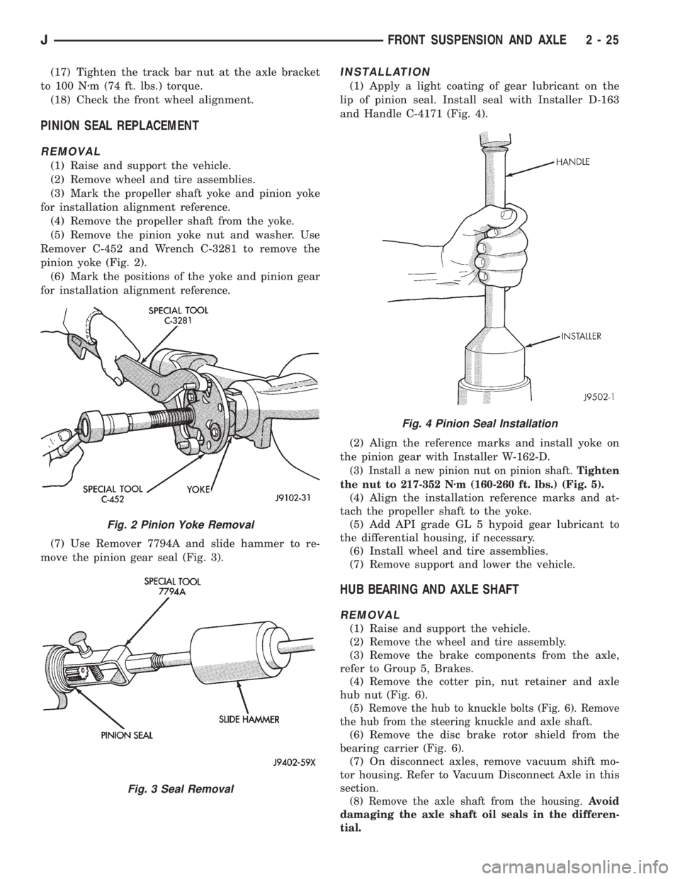
(5) Remove the pinion yoke nut and washer. Use
Remover C-452 and Wrench C-3281 to remove the
pinion yoke (Fig. 2).
(6) Mark the positions of the yoke and pinion gear
for installation alignment reference.
(7) Use Remover 7794A and slide hammer to re-
move the pinion gear seal (Fig. 3).
INSTALLATION
(1) Apply a light coating of gear lubricant on the
lip of pinion seal. Install seal with Installer D-163
and Handle C-4171 (Fig. 4).
(2) Align the reference marks and install yoke on
the pinion gear with Installer W-162-D.
(3) Install a new pinion nut on pinion shaft.Tighten
the nut to 217-352 Nzm (160-260 ft. lbs.) (Fig. 5).
(4) Align the installation reference marks and at-
tach the propeller shaft to the yoke.
(5) Add API grade GL 5 hypoid gear lubricant to
the differential housing, if necessary.
(6) Install wheel and tire assemblies.
(7) Remove support and lower the vehicle.
HUB BEARING AND AXLE SHAFT
REMOVAL
(1) Raise and support the vehicle.
(2) Remove the wheel and tire assembly.
(3) Remove the brake components from the axle,
refer to Group 5, Brakes.
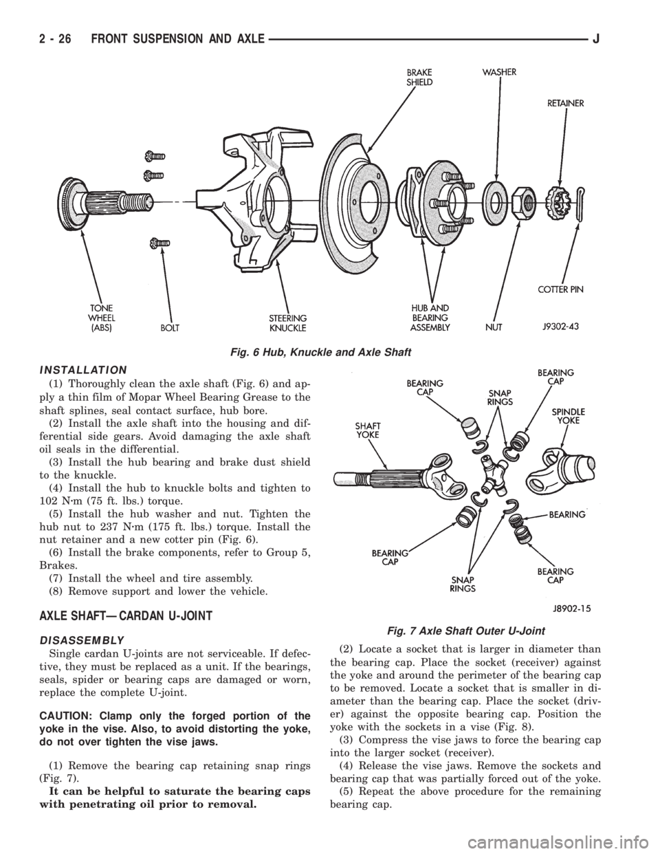
(4) Remove the cotter pin, nut retainer and axle
hub nut (Fig. 6).
(5) Remove the hub to knuckle bolts (Fig. 6). Remove
the hub from the steering knuckle and axle shaft.
(6) Remove the disc brake rotor shield from the
bearing carrier (Fig. 6).
(7) On disconnect axles, remove vacuum shift mo-
tor housing. Refer to Vacuum Disconnect Axle in this
section.
(8) Remove the axle shaft from the housing.Avoid
damaging the axle shaft oil seals in the differen-
tial.
Fig. 2 Pinion Yoke Removal
Fig. 3 Seal Removal
Fig. 4 Pinion Seal Installation
JFRONT SUSPENSION AND AXLE 2 - 25
Page 78 of 2158
INSTALLATION
(1) Thoroughly clean the axle shaft (Fig. 6) and ap-
ply a thin film of Mopar Wheel Bearing Grease to the
shaft splines, seal contact surface, hub bore.
(2) Install the axle shaft into the housing and dif-
ferential side gears. Avoid damaging the axle shaft
oil seals in the differential.
(3) Install the hub bearing and brake dust shield
to the knuckle.
(4) Install the hub to knuckle bolts and tighten to
102 Nzm (75 ft. lbs.) torque.
(5) Install the hub washer and nut. Tighten the
hub nut to 237 Nzm (175 ft. lbs.) torque. Install the
nut retainer and a new cotter pin (Fig. 6).
(6) Install the brake components, refer to Group 5,
Brakes.
(7) Install the wheel and tire assembly.
(8) Remove support and lower the vehicle.
AXLE SHAFTÐCARDAN U-JOINT
DISASSEMBLY
Single cardan U-joints are not serviceable. If defec-
tive, they must be replaced as a unit. If the bearings,
seals, spider or bearing caps are damaged or worn,
replace the complete U-joint.
CAUTION: Clamp only the forged portion of the
yoke in the vise. Also, to avoid distorting the yoke,
do not over tighten the vise jaws.
(1) Remove the bearing cap retaining snap rings
(Fig. 7).
It can be helpful to saturate the bearing caps
with penetrating oil prior to removal.(2) Locate a socket that is larger in diameter than
the bearing cap. Place the socket (receiver) against
the yoke and around the perimeter of the bearing cap
to be removed. Locate a socket that is smaller in di-
ameter than the bearing cap. Place the socket (driv-
er) against the opposite bearing cap. Position the
yoke with the sockets in a vise (Fig. 8).
(3) Compress the vise jaws to force the bearing cap
into the larger socket (receiver).
(4) Release the vise jaws. Remove the sockets and
bearing cap that was partially forced out of the yoke.
(5) Repeat the above procedure for the remaining
bearing cap.
Fig. 6 Hub, Knuckle and Axle Shaft
Fig. 7 Axle Shaft Outer U-Joint
2 - 26 FRONT SUSPENSION AND AXLEJ