1995 JEEP YJ key battery
[x] Cancel search: key batteryPage 1351 of 2158
VIBRATION DAMPER
REMOVAL
(1) Disconnect negative cable from battery.
(2) Remove the serpentine drive belt and fan
shroud.
(3) Remove the vibration damper retaining bolt
and washer.
(4) Use Vibration Damper Removal Tool 7697 to re-
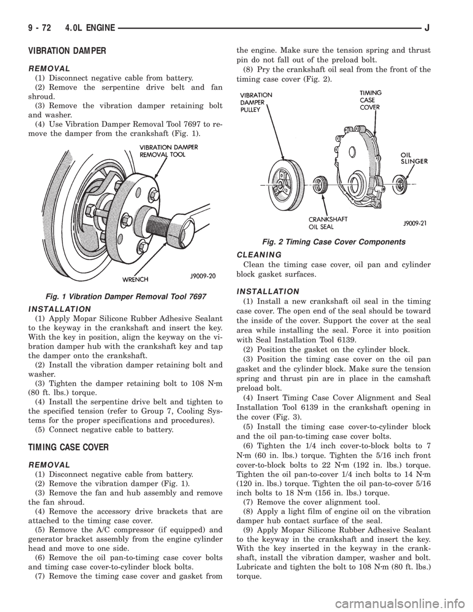
move the damper from the crankshaft (Fig. 1).
INSTALLATION
(1) Apply Mopar Silicone Rubber Adhesive Sealant
to the keyway in the crankshaft and insert the key.
With the key in position, align the keyway on the vi-
bration damper hub with the crankshaft key and tap
the damper onto the crankshaft.
(2) Install the vibration damper retaining bolt and
washer.
(3) Tighten the damper retaining bolt to 108 Nzm
(80 ft. lbs.) torque.
(4) Install the serpentine drive belt and tighten to
the specified tension (refer to Group 7, Cooling Sys-
tems for the proper specifications and procedures).
(5) Connect negative cable to battery.
TIMING CASE COVER
REMOVAL
(1) Disconnect negative cable from battery.
(2) Remove the vibration damper (Fig. 1).
(3) Remove the fan and hub assembly and remove
the fan shroud.
(4) Remove the accessory drive brackets that are
attached to the timing case cover.
(5) Remove the A/C compressor (if equipped) and
generator bracket assembly from the engine cylinder
head and move to one side.
(6) Remove the oil pan-to-timing case cover bolts
and timing case cover-to-cylinder block bolts.
(7) Remove the timing case cover and gasket fromthe engine. Make sure the tension spring and thrust
pin do not fall out of the preload bolt.
(8) Pry the crankshaft oil seal from the front of the
timing case cover (Fig. 2).
CLEANING
Clean the timing case cover, oil pan and cylinder
block gasket surfaces.
INSTALLATION
(1) Install a new crankshaft oil seal in the timing
case cover. The open end of the seal should be toward
the inside of the cover. Support the cover at the seal
area while installing the seal. Force it into position
with Seal Installation Tool 6139.
(2) Position the gasket on the cylinder block.
(3) Position the timing case cover on the oil pan
gasket and the cylinder block. Make sure the tension
spring and thrust pin are in place in the camshaft
preload bolt.
(4) Insert Timing Case Cover Alignment and Seal
Installation Tool 6139 in the crankshaft opening in
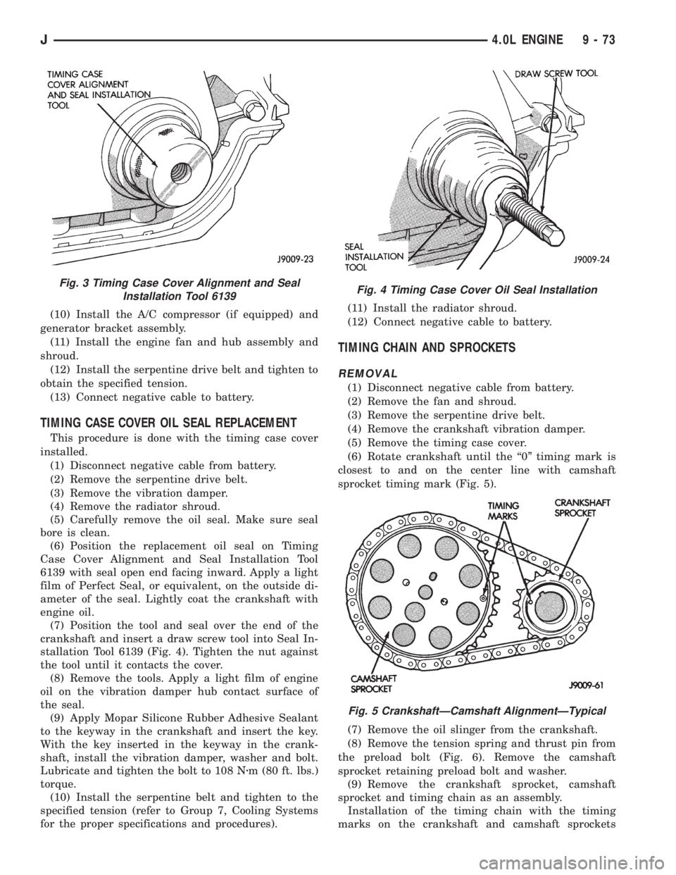
the cover (Fig. 3).
(5) Install the timing case cover-to-cylinder block
and the oil pan-to-timing case cover bolts.
(6) Tighten the 1/4 inch cover-to-block bolts to 7
Nzm (60 in. lbs.) torque. Tighten the 5/16 inch front
cover-to-block bolts to 22 Nzm (192 in. lbs.) torque.
Tighten the oil pan-to-cover 1/4 inch bolts to 14 Nzm
(120 in. lbs.) torque. Tighten the oil pan-to-cover 5/16
inch bolts to 18 Nzm (156 in. lbs.) torque.
(7) Remove the cover alignment tool.
(8) Apply a light film of engine oil on the vibration
damper hub contact surface of the seal.
(9) Apply Mopar Silicone Rubber Adhesive Sealant
to the keyway in the crankshaft and insert the key.
With the key inserted in the keyway in the crank-
shaft, install the vibration damper, washer and bolt.
Lubricate and tighten the bolt to 108 Nzm (80 ft. lbs.)
torque.Fig. 1 Vibration Damper Removal Tool 7697
Fig. 2 Timing Case Cover Components
9 - 72 4.0L ENGINEJ
Page 1352 of 2158
(10) Install the A/C compressor (if equipped) and
generator bracket assembly.
(11) Install the engine fan and hub assembly and
shroud.
(12) Install the serpentine drive belt and tighten to
obtain the specified tension.
(13) Connect negative cable to battery.
TIMING CASE COVER OIL SEAL REPLACEMENT
This procedure is done with the timing case cover
installed.
(1) Disconnect negative cable from battery.
(2) Remove the serpentine drive belt.
(3) Remove the vibration damper.
(4) Remove the radiator shroud.
(5) Carefully remove the oil seal. Make sure seal
bore is clean.
(6) Position the replacement oil seal on Timing
Case Cover Alignment and Seal Installation Tool
6139 with seal open end facing inward. Apply a light
film of Perfect Seal, or equivalent, on the outside di-
ameter of the seal. Lightly coat the crankshaft with
engine oil.
(7) Position the tool and seal over the end of the
crankshaft and insert a draw screw tool into Seal In-
stallation Tool 6139 (Fig. 4). Tighten the nut against
the tool until it contacts the cover.
(8) Remove the tools. Apply a light film of engine
oil on the vibration damper hub contact surface of
the seal.
(9) Apply Mopar Silicone Rubber Adhesive Sealant
to the keyway in the crankshaft and insert the key.
With the key inserted in the keyway in the crank-
shaft, install the vibration damper, washer and bolt.
Lubricate and tighten the bolt to 108 Nzm (80 ft. lbs.)
torque.
(10) Install the serpentine belt and tighten to the
specified tension (refer to Group 7, Cooling Systems
for the proper specifications and procedures).(11) Install the radiator shroud.
(12) Connect negative cable to battery.
TIMING CHAIN AND SPROCKETS
REMOVAL
(1) Disconnect negative cable from battery.
(2) Remove the fan and shroud.
(3) Remove the serpentine drive belt.
(4) Remove the crankshaft vibration damper.
(5) Remove the timing case cover.
(6) Rotate crankshaft until the ``0'' timing mark is
closest to and on the center line with camshaft
sprocket timing mark (Fig. 5).
(7) Remove the oil slinger from the crankshaft.
(8) Remove the tension spring and thrust pin from
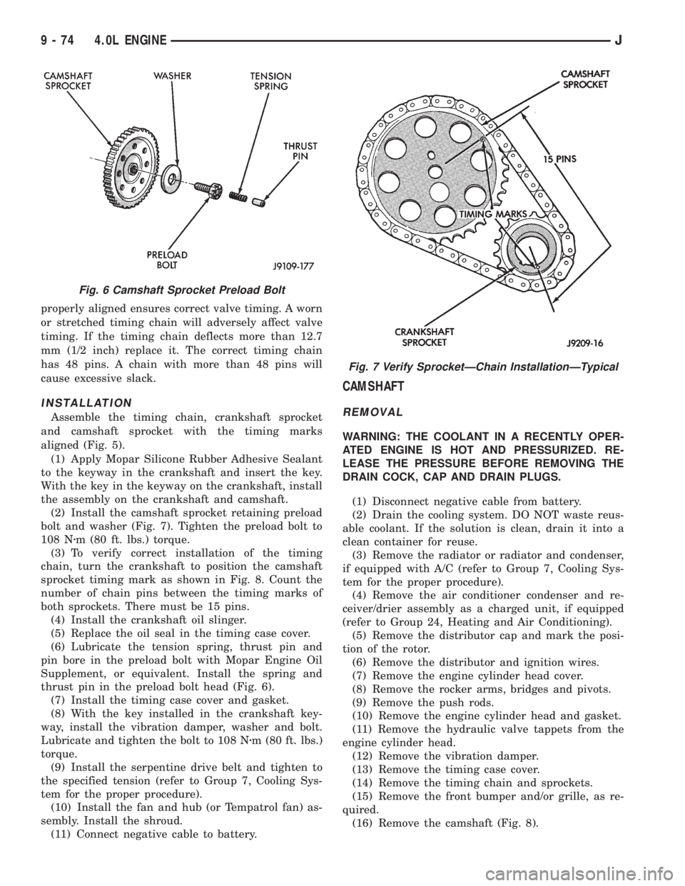
the preload bolt (Fig. 6). Remove the camshaft
sprocket retaining preload bolt and washer.
(9) Remove the crankshaft sprocket, camshaft
sprocket and timing chain as an assembly.
Installation of the timing chain with the timing
marks on the crankshaft and camshaft sprockets
Fig. 3 Timing Case Cover Alignment and Seal
Installation Tool 6139Fig. 4 Timing Case Cover Oil Seal Installation
Fig. 5 CrankshaftÐCamshaft AlignmentÐTypical
J4.0L ENGINE 9 - 73
Page 1353 of 2158
properly aligned ensures correct valve timing. A worn
or stretched timing chain will adversely affect valve
timing. If the timing chain deflects more than 12.7
mm (1/2 inch) replace it. The correct timing chain
has 48 pins. A chain with more than 48 pins will
cause excessive slack.
INSTALLATION
Assemble the timing chain, crankshaft sprocket
and camshaft sprocket with the timing marks
aligned (Fig. 5).
(1) Apply Mopar Silicone Rubber Adhesive Sealant
to the keyway in the crankshaft and insert the key.
With the key in the keyway on the crankshaft, install
the assembly on the crankshaft and camshaft.
(2) Install the camshaft sprocket retaining preload
bolt and washer (Fig. 7). Tighten the preload bolt to
108 Nzm (80 ft. lbs.) torque.
(3) To verify correct installation of the timing
chain, turn the crankshaft to position the camshaft
sprocket timing mark as shown in Fig. 8. Count the
number of chain pins between the timing marks of
both sprockets. There must be 15 pins.
(4) Install the crankshaft oil slinger.
(5) Replace the oil seal in the timing case cover.
(6) Lubricate the tension spring, thrust pin and
pin bore in the preload bolt with Mopar Engine Oil
Supplement, or equivalent. Install the spring and
thrust pin in the preload bolt head (Fig. 6).
(7) Install the timing case cover and gasket.
(8) With the key installed in the crankshaft key-
way, install the vibration damper, washer and bolt.
Lubricate and tighten the bolt to 108 Nzm (80 ft. lbs.)
torque.
(9) Install the serpentine drive belt and tighten to
the specified tension (refer to Group 7, Cooling Sys-
tem for the proper procedure).
(10) Install the fan and hub (or Tempatrol fan) as-
sembly. Install the shroud.
(11) Connect negative cable to battery.
CAMSHAFT
REMOVAL
WARNING: THE COOLANT IN A RECENTLY OPER-
ATED ENGINE IS HOT AND PRESSURIZED. RE-
LEASE THE PRESSURE BEFORE REMOVING THE
DRAIN COCK, CAP AND DRAIN PLUGS.
(1) Disconnect negative cable from battery.
(2) Drain the cooling system. DO NOT waste reus-
able coolant. If the solution is clean, drain it into a
clean container for reuse.
(3) Remove the radiator or radiator and condenser,
if equipped with A/C (refer to Group 7, Cooling Sys-
tem for the proper procedure).
(4) Remove the air conditioner condenser and re-
ceiver/drier assembly as a charged unit, if equipped
(refer to Group 24, Heating and Air Conditioning).
(5) Remove the distributor cap and mark the posi-
tion of the rotor.
(6) Remove the distributor and ignition wires.
(7) Remove the engine cylinder head cover.
(8) Remove the rocker arms, bridges and pivots.
(9) Remove the push rods.
(10) Remove the engine cylinder head and gasket.
(11) Remove the hydraulic valve tappets from the
engine cylinder head.
(12) Remove the vibration damper.
(13) Remove the timing case cover.
(14) Remove the timing chain and sprockets.
(15) Remove the front bumper and/or grille, as re-
quired.
(16) Remove the camshaft (Fig. 8).
Fig. 6 Camshaft Sprocket Preload Bolt
Fig. 7 Verify SprocketÐChain InstallationÐTypical
9 - 74 4.0L ENGINEJ
Page 1421 of 2158
MULTI-PORT FUEL INJECTION (MFI)ÐCOMPONENT DESCRIPTION/SYSTEM
OPERATION
INDEX
page page
Air Cleaner.............................. 29
Air Conditioning (A/C) Clutch RelayÐPCM Output . 26
Air Conditioning (A/C) ControlsÐPCM Input...... 21
Auto Shutdown (ASD) RelayÐPCM Output...... 26
Automatic Shutdown (ASD) SenseÐPCM Input . . . 21
Battery VoltageÐPCM Input................. 21
Brake SwitchÐPCM Input................... 22
Camshaft Position SensorÐPCM Input......... 22
Crankshaft Position SensorÐPCM Input........ 22
Data Link ConnectorÐPCM Input............. 22
Data Link ConnectorÐPCM Output............ 27
EMR LampÐPCM Output................... 27
Engine Coolant Temperature SensorÐPCM Input . 23
Extended Idle SwitchÐPCM Input............. 23
Fuel InjectorsÐPCM Output................. 27
Fuel Pressure Regulator.................... 33
Fuel Pump RelayÐPCM Output.............. 27
Fuel Rail................................ 33
General Information....................... 19
Generator FieldÐPCM Output................ 27
Generator LampÐPCM Output............... 27
Idle Air Control (IAC) MotorÐPCM Output....... 27
Ignition Circuit SenseÐPCM Input............. 23
Ignition CoilÐPCM Output................... 28Intake Manifold Air Temperature SensorÐ
PCM Input............................. 22
Malfunction Indicator LampÐPCM Output....... 28
Manifold Absolute Pressure (MAP) SensorÐPCM
Input................................. 23
Open Loop/Closed Loop Modes of Operation..... 30
Oxygen (O2S) SensorÐPCM Input............ 24
Park/Neutral SwitchÐPCM Input.............. 24
Power Ground........................... 24
Power Steering Pressure SwitchÐPCM Input.... 24
Powertrain Control Module (PCM)............. 20
Radiator Fan RelayÐPCM Output............. 28
SCI ReceiveÐPCM Input................... 24
SCI TransmitÐPCM Output.................. 29
Sensor ReturnÐPCM Input.................. 25
Shift IndicatorÐPCM Output................. 29
Speed ControlÐPCM Input.................. 25
Speed ControlÐPCM Output................. 29
TachometerÐPCM Output................... 29
Throttle Body............................ 33
Throttle Position Sensor (TPS)ÐPCM Input...... 25
Torque Converter Clutch RelayÐPCM Output.... 29
Vehicle Speed SensorÐPCM Input............ 25
GENERAL INFORMATION
All 2.5L 4-cylinder and 4.0L 6-cylinder engines are
equipped with sequential Multi-Port Fuel Injection
(MFI). The MFI system provides precise air/fuel ra-
tios for all driving conditions.
The Powertrain Control Module (PCM) operates
the fuel system. The PCM was formerly referred to
as the SBEC or engine controller. The PCM is a pre-
programmed, dual microprocessor digital computer. It
regulates ignition timing, air-fuel ratio, emission con-
trol devices, charging system, speed control, air con-
ditioning compressor clutch engagement and idle
speed. The PCM can adapt its programming to meet
changing operating conditions.
Powertrain Control Module (PCM) Inputsrep-
resent the instantaneous engine operating conditions.
Air-fuel mixture and ignition timing calibrations for
various driving and atmospheric conditions are pre-
programmed into the PCM. The PCM monitors and
analyzes various inputs. It then computes engine fuel
and ignition timing requirements based on these in-
puts. Fuel delivery control and ignition timing will
then be adjusted accordingly.
Other inputs to the PCM are provided by the brake
light switch, air conditioning select switch and the
speed control switches. All inputs to the PCM are
converted into signals.
Electrically operated fuel injectors spray fuel inprecise metered amounts into the intake port directly
above the intake valve. The injectors are fired in a
specific sequence by the PCM. The PCM maintains
an air/fuel ratio of 14.7 to 1 by constantly adjusting
injector pulse width. Injector pulse width is the
length of time that the injector opens and sprays fuel
into the chamber. The PCM adjusts injector pulse
width by opening and closing the ground path to the
injector.
Manifold absolute pressure (air density) and engine
rpm (speed) are the primary inputs that determine
fuel injector pulse width. The PCM also monitors
other inputs when adjusting air-fuel ratio.
Inputs That Effect Fuel Injector Pulse Width:
²Exhaust gas oxygen content
²Engine coolant temperature
²Manifold absolute pressure (MAP)
²Engine speed
²Throttle position
²Battery voltage
²Air conditioning selection
²Transmission gear selection (automatic transmis-
sions only)
²Speed control
The powertrain control module (PCM) adjusts igni-
tion timing by controlling ignition coil operation. The
ignition coil receives battery voltage when the igni-
tion key is in the run or starter position. The PCM
JFUEL SYSTEM COMPONENT DESCRIPTION/SYSTEM OPERATION 14 - 19
Page 1456 of 2158
EXAMPLES:
²If the lamp (Figs. 45 or 46) flashes 1 time, pauses
and flashes 2 more times, a flashing Diagnostic Trou-
ble Code (DTC) number 12 is indicated. If this code is
observed, it is indicating that the battery has been
disconnected within the last 50 key-on cycles. It
could also indicate that battery voltage has been dis-
connected to the PCM. In either case, other DTC's
may have been erased.
²If the lamp flashes 4 times, pauses and flashes 1
more time, a flashing Diagnostic Trouble Code (DTC)
number 41 is indicated.
²If the lamp flashes 4 times, pauses and flashes 6
more times, a flashing Diagnostic Trouble Code
(DTC) number 46 is indicated.
After any stored DTC information has been ob-
served, the display will end with a flashing DTC
number 55. This will indicate the end of all stored in-
formation.
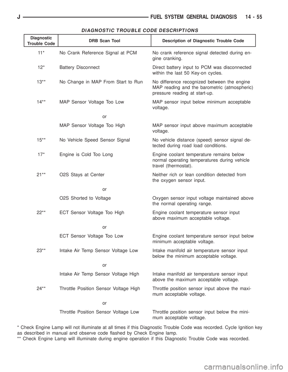
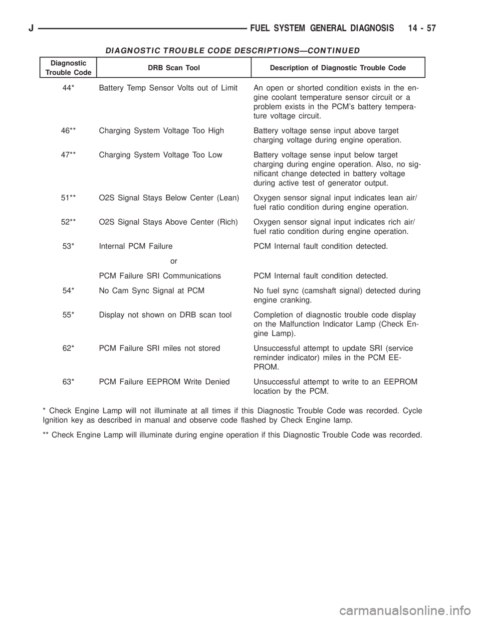
Refer to the Diagnostic Trouble Code (DTC) charts
for DTC identification.If the problem is repaired or ceases to exist, the
Powertrain Control Module (PCM) cancels the DTC
after 51 engine starts.
Diagnostic Trouble Codes indicate the results of a
failure, but never identify the failed component di-
rectly.
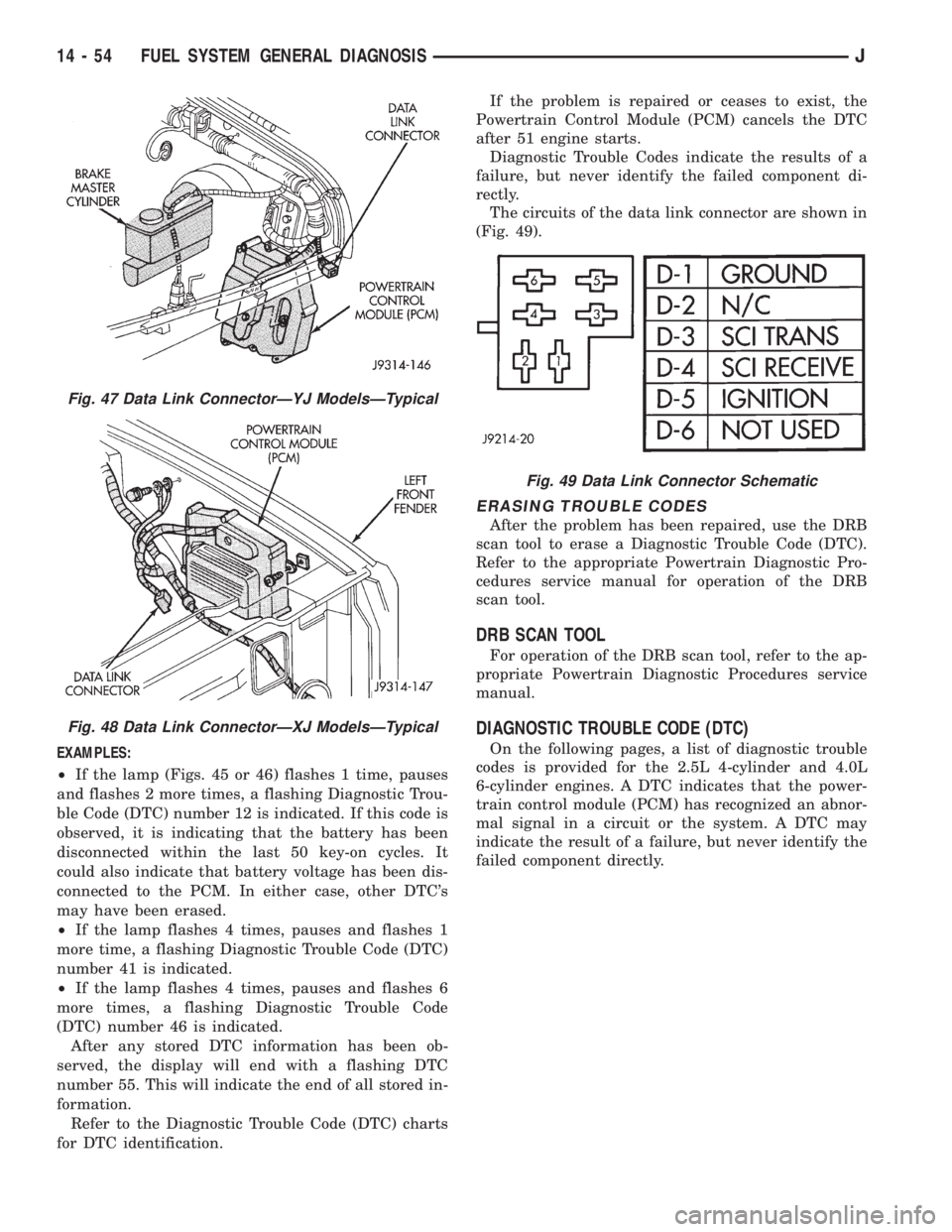
The circuits of the data link connector are shown in
(Fig. 49).
ERASING TROUBLE CODES
After the problem has been repaired, use the DRB
scan tool to erase a Diagnostic Trouble Code (DTC).
Refer to the appropriate Powertrain Diagnostic Pro-
cedures service manual for operation of the DRB
scan tool.
DRB SCAN TOOL
For operation of the DRB scan tool, refer to the ap-
propriate Powertrain Diagnostic Procedures service
manual.
DIAGNOSTIC TROUBLE CODE (DTC)
On the following pages, a list of diagnostic trouble
codes is provided for the 2.5L 4-cylinder and 4.0L
6-cylinder engines. A DTC indicates that the power-
train control module (PCM) has recognized an abnor-
mal signal in a circuit or the system. A DTC may
indicate the result of a failure, but never identify the
failed component directly.
Fig. 47 Data Link ConnectorÐYJ ModelsÐTypical
Fig. 48 Data Link ConnectorÐXJ ModelsÐTypical
Fig. 49 Data Link Connector Schematic
14 - 54 FUEL SYSTEM GENERAL DIAGNOSISJ
Page 1457 of 2158
DIAGNOSTIC TROUBLE CODE DESCRIPTIONS
Diagnostic
Trouble CodeDRB Scan Tool Description of Diagnostic Trouble Code
11* No Crank Reference Signal at PCM No crank reference signal detected during en-
gine cranking.
12* Battery Disconnect Direct battery input to PCM was disconnected
within the last 50 Key-on cycles.
13** No Change in MAP From Start to Run No difference recognized between the engine
MAP reading and the barometric (atmospheric)
pressure reading at start-up.
14** MAP Sensor Voltage Too Low MAP sensor input below minimum acceptable
voltage.
or
MAP Sensor Voltage Too High MAP sensor input above maximum acceptable
voltage.
15** No Vehicle Speed Sensor Signal No vehicle distance (speed) sensor signal de-
tected during road load conditions.
17* Engine is Cold Too Long Engine coolant temperature remains below
normal operating temperatures during vehicle
travel (thermostat).
21** O2S Stays at Center Neither rich or lean condition detected from
the oxygen sensor input.
or
O2S Shorted to Voltage Oxygen sensor input voltage maintained above
the normal operating range.
22** ECT Sensor Voltage Too High Engine coolant temperature sensor input
above maximum acceptable voltage.
or
ECT Sensor Voltage Too Low Engine coolant temperature sensor input below
minimum acceptable voltage.
23** Intake Air Temp Sensor Voltage Low Intake manifold air temperature sensor input
below the minimum acceptable voltage.
or
Intake Air Temp Sensor Voltage High Intake manifold air temperature sensor input
above the maximum acceptable voltage.
24** Throttle Position Sensor Voltage High Throttle position sensor input above the maxi-
mum acceptable voltage.
or
Throttle Position Sensor Voltage Low Throttle position sensor input below the mini-
mum acceptable voltage.
* Check Engine Lamp will not illuminate at all times if this Diagnostic Trouble Code was recorded. Cycle Ignition key
as described in manual and observe code flashed by Check Engine lamp.
** Check Engine Lamp will illuminate during engine operation if this Diagnostic Trouble Code was recorded.
JFUEL SYSTEM GENERAL DIAGNOSIS 14 - 55
Page 1459 of 2158
DIAGNOSTIC TROUBLE CODE DESCRIPTIONSÐCONTINUED
Diagnostic
Trouble CodeDRB Scan Tool Description of Diagnostic Trouble Code
44* Battery Temp Sensor Volts out of Limit An open or shorted condition exists in the en-
gine coolant temperature sensor circuit or a
problem exists in the PCM's battery tempera-
ture voltage circuit.
46** Charging System Voltage Too High Battery voltage sense input above target
charging voltage during engine operation.
47** Charging System Voltage Too Low Battery voltage sense input below target
charging during engine operation. Also, no sig-
nificant change detected in battery voltage
during active test of generator output.
51** O2S Signal Stays Below Center (Lean) Oxygen sensor signal input indicates lean air/
fuel ratio condition during engine operation.
52** O2S Signal Stays Above Center (Rich) Oxygen sensor signal input indicates rich air/
fuel ratio condition during engine operation.
53* Internal PCM Failure PCM Internal fault condition detected.
or
PCM Failure SRI Communications PCM Internal fault condition detected.
54* No Cam Sync Signal at PCM No fuel sync (camshaft signal) detected during
engine cranking.
55* Display not shown on DRB scan tool Completion of diagnostic trouble code display
on the Malfunction Indicator Lamp (Check En-
gine Lamp).
62* PCM Failure SRI miles not stored Unsuccessful attempt to update SRI (service
reminder indicator) miles in the PCM EE-
PROM.
63* PCM Failure EEPROM Write Denied Unsuccessful attempt to write to an EEPROM
location by the PCM.
* Check Engine Lamp will not illuminate at all times if this Diagnostic Trouble Code was recorded. Cycle
Ignition key as described in manual and observe code flashed by Check Engine lamp.
** Check Engine Lamp will illuminate during engine operation if this Diagnostic Trouble Code was recorded.
JFUEL SYSTEM GENERAL DIAGNOSIS 14 - 57
Page 1538 of 2158
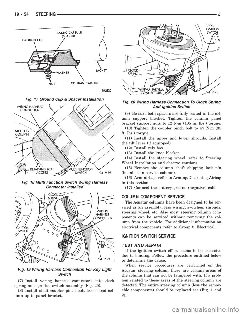
(7) Install wiring harness connectors onto clock
spring and ignition switch assembly (Fig. 20).
(8) Install shaft coupler pinch bolt loose, load col-
umn up to panel bracket.(9) Be sure both spacers are fully seated in the col-
umn support bracket. Tighten the column panel
bracket support nuts to 12 Nzm (105 in. lbs.) torque.
(10) Tighten the coupler pinch bolt to 47 Nzm (35
ft. lbs.) torque.
(11) Install the upper and lower shrouds. Install
the tilt lever (if equipped).
(12) Install rely box.
(13) Install the knee blocker.
(14) Install the steering wheel, refer to Steering
Wheel Installation and observe cautions.
(15) Remove the column shaft shipping lock pin
(installed in service column).
(16) Arm airbag, refer to Arming/Disarming Airbag
in this section.
(17) Connect the battery ground (negative) cable.
COLUMN COMPONENT SERVICE
The Acustar columns have been designed to be ser-
viced as an assembly; less wiring, switches, shrouds,
steering wheel, etc. Also most steering column com-
ponents can be serviced without removing the col-
umn from the vehicle. For additional information on
electrical components refer to Group 8, Electrical.
IGNITION SWITCH SERVICE
TEST AND REPAIR
If the ignition switch effort seems to be excessive
due to binding. Follow the procedure outlined below
to determine the cause.
When service procedures are performed on the
Acustar steering column there are certain areas of
the column that can not be tampered with. If a prob-
lem related to these areas of the steering column are
detected. The entire steering column (less the remov-
able components) should be replaced see (Fig. 1 and
2).
Fig. 17 Ground Clip & Spacer Installation
Fig. 18 Multi Function Switch Wiring Harness
Connector Installed
Fig. 19 Wiring Harness Connection For Key Light
Switch
Fig. 20 Wiring Harness Connection To Clock Spring
And Ignition Switch
19 - 54 STEERINGJ