1995 JEEP YJ engine overheat
[x] Cancel search: engine overheatPage 1376 of 2158
EXHAUST SYSTEM AND INTAKE MANIFOLD
CONTENTS
page page
EXHAUST SYSTEM....................... 1
EXHAUST SYSTEM DIAGNOSIS............. 2SERVICE PROCEDURES................... 3
TORQUE SPECIFICATIONS................ 10
EXHAUST SYSTEM
GENERAL INFORMATION
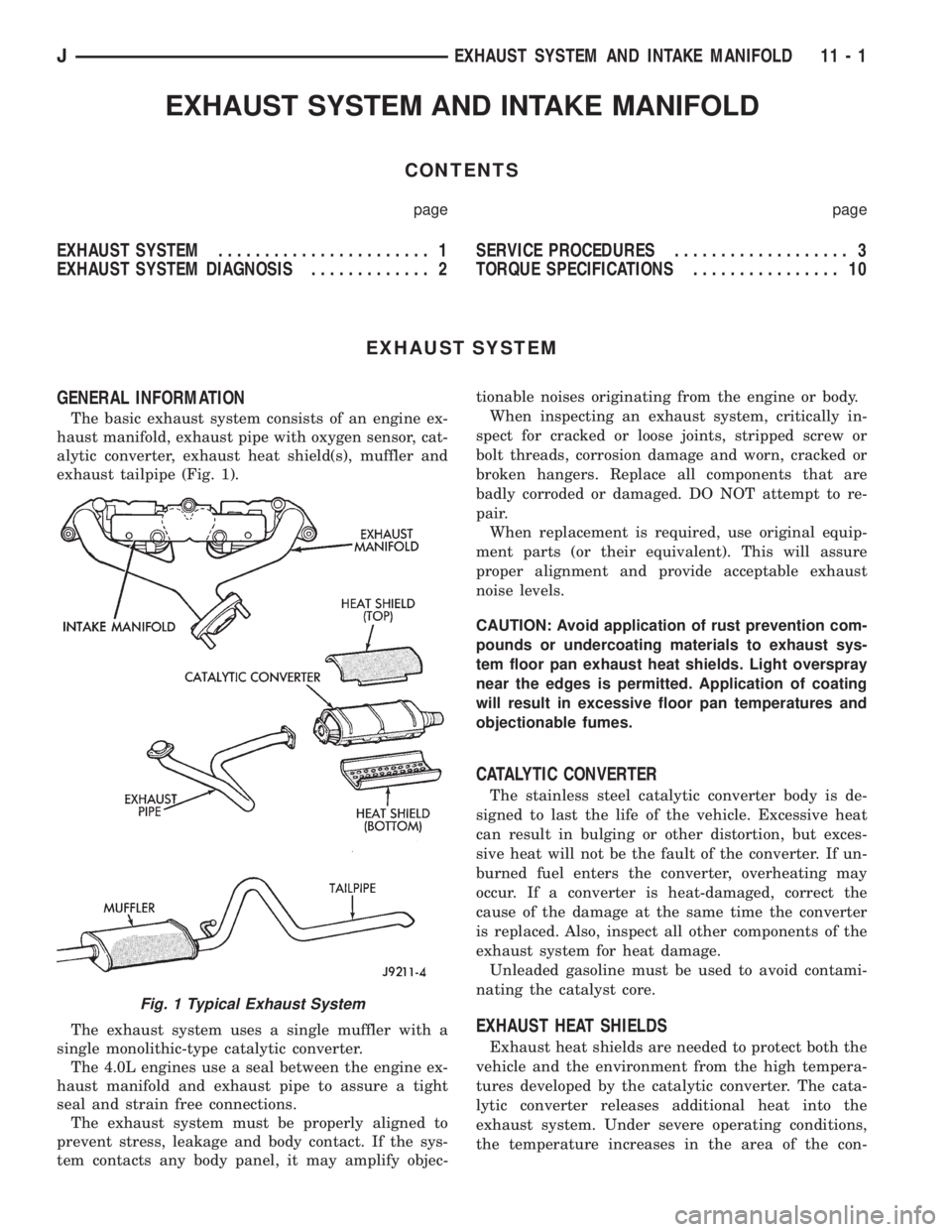
The basic exhaust system consists of an engine ex-
haust manifold, exhaust pipe with oxygen sensor, cat-
alytic converter, exhaust heat shield(s), muffler and
exhaust tailpipe (Fig. 1).
The exhaust system uses a single muffler with a
single monolithic-type catalytic converter.
The 4.0L engines use a seal between the engine ex-
haust manifold and exhaust pipe to assure a tight
seal and strain free connections.
The exhaust system must be properly aligned to
prevent stress, leakage and body contact. If the sys-
tem contacts any body panel, it may amplify objec-tionable noises originating from the engine or body.
When inspecting an exhaust system, critically in-
spect for cracked or loose joints, stripped screw or
bolt threads, corrosion damage and worn, cracked or
broken hangers. Replace all components that are
badly corroded or damaged. DO NOT attempt to re-
pair.
When replacement is required, use original equip-
ment parts (or their equivalent). This will assure
proper alignment and provide acceptable exhaust
noise levels.
CAUTION: Avoid application of rust prevention com-
pounds or undercoating materials to exhaust sys-
tem floor pan exhaust heat shields. Light overspray
near the edges is permitted. Application of coating
will result in excessive floor pan temperatures and
objectionable fumes.
CATALYTIC CONVERTER
The stainless steel catalytic converter body is de-
signed to last the life of the vehicle. Excessive heat
can result in bulging or other distortion, but exces-
sive heat will not be the fault of the converter. If un-
burned fuel enters the converter, overheating may
occur. If a converter is heat-damaged, correct the
cause of the damage at the same time the converter
is replaced. Also, inspect all other components of the
exhaust system for heat damage.
Unleaded gasoline must be used to avoid contami-
nating the catalyst core.
EXHAUST HEAT SHIELDS
Exhaust heat shields are needed to protect both the
vehicle and the environment from the high tempera-
tures developed by the catalytic converter. The cata-
lytic converter releases additional heat into the
exhaust system. Under severe operating conditions,
the temperature increases in the area of the con-
Fig. 1 Typical Exhaust System
JEXHAUST SYSTEM AND INTAKE MANIFOLD 11 - 1
Page 1383 of 2158
CAUTION: When disconnecting the cruise control
connector at the throttle body, DO NOT pry the con-
nector off with pliers or screwdriver. Use finger
pressure only. Prying the connector off could break
it.
(9) Disconnect the electrical connectors. Pull the
harnesses away from the manifold.
²The throttle position sensor.
²The idle speed control motor.
²The coolant temperature sensor at the thermostat.
²The manifold air temperature sensor at the intake
manifold.
²The fuel injectors.
²The oxygen sensor.
(10) Disconnect the crankcase ventilation (CCV)
vacuum hose and manifold absolute pressure (MAP)
sensor vacuum hose connector at the intake mani-
fold.
(11) Disconnect vacuum hose from vacuum port on
the intake manifold.
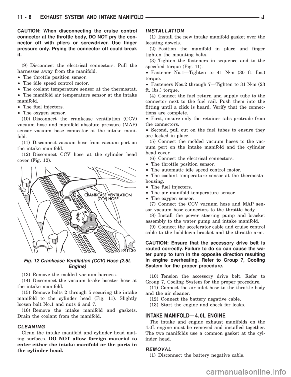
(12) Disconnect CCV hose at the cylinder head
cover (Fig. 12).
(13) Remove the molded vacuum harness.
(14) Disconnect the vacuum brake booster hose at
the intake manifold.
(15) Remove bolts 2 through 5 securing the intake
manifold to the cylinder head (Fig. 11). Slightly
loosen bolt No.1 and nuts 6 and 7.
(16) Remove the intake manifold and gaskets.
Drain the coolant from the manifold.
CLEANING
Clean the intake manifold and cylinder head mat-
ing surfaces.DO NOT allow foreign material to
enter either the intake manifold or the ports in
the cylinder head.
INSTALLATION
(1) Install the new intake manifold gasket over the
locating dowels.
(2) Position the manifold in place and finger
tighten the mounting bolts.
(3) Tighten the fasteners in sequence and to the
specified torque (Fig. 11).
²Fastener No.1ÐTighten to 41 Nzm (30 ft. lbs.)
torque.
²Fasteners Nos.2 through 7ÐTighten to 31 Nzm (23
ft. lbs.) torque.
(4) Connect the fuel return and supply tube to the
connector next to the fuel rail. Push them into the
fitting until a click is heard. Verify that the connec-
tions are complete.
²First, ensure only the retainer tabs protrude from
the connectors.
²Second, pull out on the fuel tubes to ensure they
are locked in place.
(5) Connect the molded vacuum hoses to the vac-
uum port on the intake manifold and the cylinder
head cover.
(6) Connect the electrical connectors.
²The throttle position sensor.
²The automatic idle speed control motor.
²The coolant temperature sensor at the thermostat
housing.
²The fuel injectors.
²The air manifold temperature sensor.
²The oxygen sensor.
(7) Connect the CCV vacuum hose and MAP sen-
sor vacuum hose connectors to the throttle body.
(8) Install the power steering pump and bracket
assembly to the water pump and intake manifold.
(9) Connect the accelerator cable and cruise control
cable to the holddown bracket and the throttle arm.
CAUTION: Ensure that the accessory drive belt is
routed correctly. Failure to do so can cause the wa-
ter pump to turn in the opposite direction resulting
in engine overheating. Refer to Group 7, Cooling
System for the proper procedure.
(10) Tension the accessory drive belt. Refer to
Group 7, Cooling System for the proper procedure.
(11) Connect the air inlet hose to the throttle body
and the air cleaner.
(12) Connect the battery negative cable.
(13) Start the engine and check for leaks.
INTAKE MANIFOLDÐ4.0L ENGINE
The intake and engine exhaust manifolds on the
4.0L engine must be removed and installed together.
The two manifolds use a common gasket at the cyl-
inder head.
REMOVAL
(1) Disconnect the battery negative cable.
Fig. 12 Crankcase Ventilation (CCV) Hose (2.5L
Engine)
11 - 8 EXHAUST SYSTEM AND INTAKE MANIFOLDJ
Page 1565 of 2158

happens when the container delivery mechanism is im-
properly calibrated. Always check the lubricant level af-
ter filling to avoid an under fill condition.
A correct lubricant level check can only be made
when the vehicle is level; use a drive-on hoist to en-
sure this. Also allow the lubricant to settle for a
minute or so before checking. These recommenda-
tions will ensure an accurate check and avoid an un-
der-or-overfill condition.
HARD SHIFTING
Hard shifting is usually caused by a low lubricant
level, improper or contaminated lubricants, compo-
nent damage, incorrect clutch adjustment, or by a
damaged clutch pressure plate or disc.
Substantial lubricant leaks can result in gear, shift
rail, synchro and bearing damage. If a leak goes un-
detected for an extended period, the first indications
of a problem are usually hard shifting and noise.
Incorrect or contaminated lubricants can also con-
tribute to hard shifting. The consequence of using
non-recommended lubricants is noise, excessive wear,
internal bind and hard shifting.
Improper clutch release is a frequent cause of hard
shifting. Incorrect adjustment or a worn, damaged
pressure plate or disc can cause incorrect release. If
the clutch problem is advanced, gear clash during
shifts can result.
Worn or damaged synchro rings can cause gear clash
when shifting into any forward gear. In some new or re-
built transmissions, new synchro rings may tend to
stick slightly causing hard or noisy shifts. In most
cases, this condition will decline as the rings wear-in.
TRANSMISSION NOISE
Most manual transmissions make some noise dur-
ing normal operation. Rotating gears generate a mild
whine that is audible but only at extreme speeds.
Severe, highly audible transmission noise is gener-
ally the result of a lubricant problem. Insufficient,
improper, or contaminated lubricant will promote
rapid wear of gears, synchros, shift rails, forks and
bearings. The overheating caused by a lubricant
problem, can also lead to gear breakage.
TRANSMISSION REMOVAL
(1) Shift transmission into first or third gear. Then
raise vehicle on hoist.
(2) Support engine with adjustable jack stand. Po-
sition wood block between jack and oil pan to avoid
damaging pan.
(3) Disconnect necessary exhaust system components.
(4) Remove skid plate.
(5) Disconnect rear cushion and bracket from
transmission (Fig. 5).
(6) Remove rear crossmember.
Fig. 5 Rear Mount Components (YJ Shown)
JAX 4/5 MANUAL TRANSMISSION 21 - 3
Page 1633 of 2158
(4) Apply parking brakes.
(5) Shift transmission momentarily into all gear
ranges. Then shift transmission back to Neutral.
(6) Clean top of filler tube and dipstick to keep dirt
from entering tube.
(7) Remove dipstick and check fluid level as fol-
lows:
(a) Dipstick has three fluid level indicator levels
(Fig. 1) which are: a MIN dot, an OK crosshatch
area, and a MAX fill arrow.
(b) Correct maximum level is to MAX arrow
mark. Correct acceptable level is to OK mark in
crosshatch area.
(c) Incorrect level is at or below MIN dot.
(d) If fluid is low, add only enough Mopar ATF
Plus to restore correct level. Do not overfill.
CAUTION: Do not overfill the transmission. Overfill-
ing may cause leakage out the pump vent which
can be mistaken for a pump seal leak. Overfilling
will also cause fluid aeration and foaming as the ex-
cess fluid is picked up and churned by the gear
train. This will significantly reduce fluid life.
EFFECTS OF INCORRECT FLUID LEVEL
A low fluid level allows the pump to take in air
along with the fluid. Air in the fluid will cause fluid
pressures to be low and develop slower than normal.
If the transmission is overfilled, the gears churn
the fluid into foam. This aerates the fluid causing the
same conditions that occur with a low level.
In either case, air bubbles cause fluid overheating,
oxidation and varnish buildup which interferes with
valve, clutch and servo operation. Foaming also
causes fluid expansion which can result in fluid over-
flow from the transmission vent or fill tube. Fluid
overflow can easily be mistaken for a leak if inspec-
tion is not careful.
TRANSMISSION THROTTLE VALVE CABLE
ADJUSTMENT
Throttle cable adjustment is important to proper
operation. This adjustment positions the throttle
valve which controls shift speed, quality and part
throttle downshift sensitivity.
If cable adjustment setting is too short, early shifts
and slippage between shifts may occur. If the setting
is too long, shifts may be delayed and part throttle
downshifts may be very sensitive. Refer to the In-Ve-
hicle Service section for adjustment procedure.
GEARSHIFT CABLE/LINKAGE ADJUSTMENT
Gearshift cable/linkage adjustment is important be-
cause it positions the valve body manual valve. Incor-
rect adjustment will cause creeping in Neutral,
premature clutch wear, delayed engagement in any
gear, or a no-start in Park or Neutral position.Proper operation of the neutral start switch will
provide a quick check on adjustment. Refer to the In-
Vehicle Service section for adjustment procedure.
ROAD TEST
Before road testing, be sure the fluid level and all
cable/linkage adjustments have been checked and ad-
justed if necessary.
Observe engine performance during the road test. A
poorly tuned engine will not allow an accurate anal-
ysis of transmission operation.
Operate the transmission in all gear ranges. Check
for slippage and shift variations. Note whether the
shifts are harsh, spongy, delayed, early, or if part
throttle downshifts are sensitive.
Watch closely for slippage or engine flare which
usually indicates clutch, band or overrunning clutch
problems. If the condition is advanced, an overhaul
may be necessary to restore normal operation.
A slipping clutch or band can often be determined
by comparing which internal units are applied in the
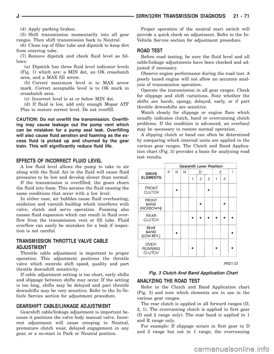
various gear ranges. The Clutch and Band Applica-
tion chart (Fig. 3) provides a basis for analyzing road
test results.
ANALYZING THE ROAD TEST
Refer to the Clutch and Band Application chart
(Fig. 3) and note which elements are in use in the
various gear ranges.
The rear clutch is applied in all forward ranges (D,
2, 1). The overrunning clutch is applied in first gear
(D and 2 range only). The rear band is applied in 1
and R range only.
For example: If slippage occurs in first gear in D
and 2 range but not in 1 range, the overrunning
Fig. 3 Clutch And Band Application Chart
J30RH/32RH TRANSMISSION DIAGNOSIS 21 - 71
Page 1636 of 2158
CONVERTER STALL TEST
Stall testing involves determining maximum engine
rpm obtainable at full throttle with the rear wheels
locked and the transmission in D range. This test
checks the holding ability of the converter overrun-
ning clutch and both of the transmission clutches.
When stall testing is completed, refer to the Stall
Speed Specifications chart and Stall Speed Diagnosis
guides.
WARNING: NEVER ALLOW ANYONE TO STAND IN
FRONT OF THE VEHICLE DURING A STALL TEST.
ALWAYS BLOCK THE FRONT WHEELS AND APPLY
THE SERVICE AND PARKING BRAKES DURING
THE TEST.
STALL TEST PROCEDURE
(1) Connect tachometer to engine.
(2) Check and adjust transmission fluid level.
(3) Start and run engine until transmission fluid
reaches normal operating temperature.
(4) Block front wheels.
(5) Fully apply service and parking brakes.
(6) Open throttle completely and record maximum
engine rpm registered on tachometer. It will take
from 3 to 10 seconds to reach maximum rpm. How-
ever, once maximum rpm has been achieved,do not
hold wide open throttle for more than 5 sec-
onds.
CAUTION: Stalling the converter causes a rapid in-
crease in fluid temperature. To avoid fluid overheat-
ing, hold wide open throttle for no more than 5
seconds after reaching peak rpm. In addition, if
more than one stall test is required, run the engine
at 1000 rpm with the transmission in Neutral for at
least 20 seconds to cool the fluid.
(7) Stall speeds should be in 1700-2150 rpm range.
CAUTION: If engine exceeds 2150 rpm, release ac-
celerator pedal immediately as transmission clutch
slippage is occurring.
(8) Shift transmission into Neutral. Run engine for
20-30 seconds at 1000 rpm to cool fluid. Then stop
engine, shift transmission into Park and release
brakes.
(9) Refer to Stall Test Diagnosis.
STALL TEST DIAGNOSIS
Stall Speed Too Low
Low stall speeds with a properly tuned engine in-
dicate a torque converter overrunning clutch prob-
lem. The condition should be confirmed by road
testing prior to converter replacement.The converter overrunning clutch is slipping when
stall speeds are 250 to 350 rpm below specified min-
imum.
A converter overrunning clutch failure will result
in sluggish acceleration in all speed ranges. It will
also require greater than normal throttle opening to
maintain cruising speeds.
Stall Speed Too High
If stall speed exceeds 2150 rpm, transmission
clutch slippage is occurring.
Stall Speed Normal But Acceleration Is Sluggish
If stall speeds are within specified range but abnor-
mal throttle opening is required for acceleration, or
to maintain cruise speeds, the converter overrunning
clutch is seized. The torque converter will have to be
replaced.
Converter Noise During Test
A whining noise caused by fluid flow is normal dur-
ing a stall test. However, loud metallic noises indi-
cate a damaged converter. To confirm that noise is
originating from the converter, operate the vehicle at
light throttle in Drive and Neutral on a hoist and lis-
ten for noise from the converter housing.
AIR PRESSURE TEST
Air pressure testing can be used to check clutch
and band operation with the transmission either in
the vehicle, or on the work bench as a final check af-
ter overhaul.
Air pressure testing requires that the oil pan and
valve body be removed from the transmission.
The servo and clutch apply passages are shown in
Figure 8.
Air Test Procedure
(1) Place one or two fingers on the clutch housing
and apply air pressure through front clutch apply
passage (Fig. 8). Piston movement can be felt and a
soft thud heard as the clutch applies.
(2) Place one or two fingers on the clutch housing
and apply air pressure through rear clutch apply
passage (Fig. 8). Piston movement can be felt and a
soft thud heard as the clutch applies.
(3) Apply air pressure to the front servo apply pas-
sage. The servo rod should extend and cause the
band to tighten around the drum. Spring tension
should release the servo when air pressure is re-
moved.
(4) Apply air pressure to the rear servo apply pas-
sage. The servo rod should extend and cause the
band to tighten around the drum. Spring tension
should release the servo when air pressure is re-
moved.
21 - 74 30RH/32RH TRANSMISSION DIAGNOSISJ
Page 1675 of 2158
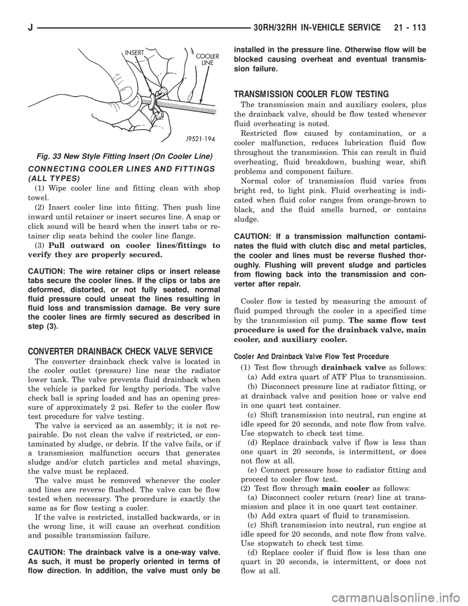
CONNECTING COOLER LINES AND FITTINGS
(ALL TYPES)
(1) Wipe cooler line and fitting clean with shop
towel.
(2) Insert cooler line into fitting. Then push line
inward until retainer or insert secures line. A snap or
click sound will be heard when the insert tabs or re-
tainer clip seats behind the cooler line flange.
(3)Pull outward on cooler lines/fittings to
verify they are properly secured.
CAUTION: The wire retainer clips or insert release
tabs secure the cooler lines. If the clips or tabs are
deformed, distorted, or not fully seated, normal
fluid pressure could unseat the lines resulting in
fluid loss and transmission damage. Be very sure
the cooler lines are firmly secured as described in
step (3).
CONVERTER DRAINBACK CHECK VALVE SERVICE
The converter drainback check valve is located in
the cooler outlet (pressure) line near the radiator
lower tank. The valve prevents fluid drainback when
the vehicle is parked for lengthy periods. The valve
check ball is spring loaded and has an opening pres-
sure of approximately 2 psi. Refer to the cooler flow
test procedure for valve testing.
The valve is serviced as an assembly; it is not re-
pairable. Do not clean the valve if restricted, or con-
taminated by sludge, or debris. If the valve fails, or if
a transmission malfunction occurs that generates
sludge and/or clutch particles and metal shavings,
the valve must be replaced.
The valve must be removed whenever the cooler
and lines are reverse flushed. The valve can be flow
tested when necessary. The procedure is exactly the
same as for flow testing a cooler.
If the valve is restricted, installed backwards, or in
the wrong line, it will cause an overheat condition
and possible transmission failure.
CAUTION: The drainback valve is a one-way valve.
As such, it must be properly oriented in terms of
flow direction. In addition, the valve must only beinstalled in the pressure line. Otherwise flow will be
blocked causing overheat and eventual transmis-
sion failure.
TRANSMISSION COOLER FLOW TESTING
The transmission main and auxiliary coolers, plus
the drainback valve, should be flow tested whenever
fluid overheating is noted.
Restricted flow caused by contamination, or a
cooler malfunction, reduces lubrication fluid flow
throughout the transmission. This can result in fluid
overheating, fluid breakdown, bushing wear, shift
problems and component failure.
Normal color of transmission fluid varies from
bright red, to light pink. Fluid overheating is indi-
cated when fluid color ranges from orange-brown to
black, and the fluid smells burned, or contains
sludge.
CAUTION: If a transmission malfunction contami-
nates the fluid with clutch disc and metal particles,
the cooler and lines must be reverse flushed thor-
oughly. Flushing will prevent sludge and particles
from flowing back into the transmission and con-
verter after repair.
Cooler flow is tested by measuring the amount of
fluid pumped through the cooler in a specified time
by the transmission oil pump.The same flow test
procedure is used for the drainback valve, main
cooler, and auxiliary cooler.
Cooler And Drainback Valve Flow Test Procedure
(1) Test flow throughdrainback valveas follows:
(a) Add extra quart of ATF Plus to transmission.
(b) Disconnect pressure line at radiator fitting, or
at drainback valve and position hose or valve end
in one quart test container.
(c) Shift transmission into neutral, run engine at
idle speed for 20 seconds, and note flow from valve.
Use stopwatch to check test time.
(d) Replace drainback valve if flow is less than
one quart in 20 seconds, is intermittent, or does
not flow at all.
(e) Connect pressure hose to radiator fitting and
proceed to cooler flow test.
(2) Test flow throughmain cooleras follows:
(a) Disconnect cooler return (rear) line at trans-
mission and place it in one quart test container.
(b) Add extra quart of fluid to transmission.
(c) Shift transmission into neutral, run engine at
idle speed for 20 seconds, and note flow from valve.
Use stopwatch to check test time.
(d) Replace cooler if fluid flow is less than one
quart in 20 seconds, is intermittent, or does not
flow at all.
Fig. 33 New Style Fitting Insert (On Cooler Line)
J30RH/32RH IN-VEHICLE SERVICE 21 - 113
Page 1740 of 2158
PRESSURE TEST ANALYSIS
If pressures in D and Reverse are higher than
specified in test, check for the following:
²throttle cable loose, worn, binding or out of adjust-
ment
²throttle valve, downshift plug, throttle cam, or pri-
mary regulator valve are sticking, worn or damaged
If pressures in D and Reverse are lower than spec-
ified in test, check for following:
²throttle cable loose, worn, binding or out of adjust-
ment
²throttle valve, downshift plug, or throttle cam
sticking, worn or damaged
²primary regulator valve sticking, worn, or dam-
aged
²oil pump gears or housing worn, or damaged
²overdrive clutch worn, or damaged
If pressures are low in D range only, check for fol-
lowing:
²forward clutch worn or damaged
²fluid leakage in D range circuit (component seal
and O-rings)
If pressures are low in Reverse only, check for fol-
lowing:
²shift cable and manual valve out of adjustment
²fluid leakage in reverse circuit (component seal
and O-rings)
²direct clutch worn or damaged
²first/reverse brake worn or damaged
TORQUE CONVERTER STALL TEST
Stall testing checks the holding ability of the trans-
mission clutches and brakes and of the torque con-
verter stator overrunning clutch.Stall speeds are
checked in both Drive and Reverse ranges with
the AW-4 transmission.
(1) Before starting test, be sure fluid level is cor-
rect and fluid is at normal operating temperature.
(2) Connect tachometer to engine. Position tachom-
eter so it can be viewed from drivers seat.
(3) Apply parking brakes and block wheels.
(4) Apply and hold service brakes.
(5) Shift transfer case into 2H position.
(6) Start engine.
WARNING: DO NOT ALLOW ANYONE TO STAND AT
THE FRONT OR REAR OF THE VEHICLE DURING
THE TEST.
(7) Shift transmission into D range.
(8) Open throttle completely and record maximum
engine rpm registered on tachometer. It takes any-
where from 4 to 10 seconds to reach maximum rpm.
However, once maximum rpm has been achieved,do
not hold wide open throttle for more than 3-4
seconds.CAUTION: Stalling the converter causes a rapid in-
crease in fluid temperature. To avoid fluid overheat-
ing, hold wide open throttle for no more than 4
seconds after reaching peak rpm. In addition, if
more than one stall test is required, run the engine
at 1000 rpm with the transmission in Neutral for at
least 20 seconds to cool the fluid.
(9) Stall speed should be in 2100-2400 rpm range
in Drive.
(10) Release throttle, shift transmission into Neu-
tral, and run engine for 20-30 seconds to cool fluid.
(11) Shift transmission into Reverse.
(12) Repeat stall test described in step (8).
(13) Stall speed in Reverse should also be in 2100-
2400 rpm range.
(14) Release accelerator pedal, shift transmission
into Neutral, and run engine for 20-30 seconds to
cool fluid.
STALL SPEED TEST ANALYSIS
If engine rpm is lower than specified in D and Re-
verse, check for the following:
²engine output/performance insufficient
²stator overrunning clutch in torque converter not
holding if engine speed was 1500 rpm or less.
If stall speed in D range is higher than specified,
check for the following:
²line pressure low
²forward clutch slipping
²No. 2 one-way clutch not holding
²overdrive one-way clutch not holding
If stall speed in Reverse was higher than specified,
check for the following:
²line pressure low
²direct clutch slipping
²first/ reverse brake slipping
²overdrive one-way clutch not holding
If stall speeds were higher than specified in both D
and Reverse, check for the following:
²low fluid level
²line pressure low
²overdrive one-way clutch not holding
TIME LAG TEST
This test checks general condition of the overdrive
clutch, forward clutch, rear clutch and first/reverse
brake. Condition is indicated by the amount of time
required for clutch/brake engagement with the en-
gine at curb idle speed. Engagement time is mea-
sured for D and Reverse positions. A stop watch is
recommended for test accuracy.
TEST PROCEDURE
(1) Check and adjust transmission fluid level if
necessary.
(2) Bring transmission to normal operating tem-
perature.
21 - 178 AW-4 TRANSMISSION DIAGNOSISJ