1995 JEEP YJ display
[x] Cancel search: displayPage 1126 of 2158
switch to ground on circuit Z1. The switch closes dur-
ing periods of high power steering pump load and
low engine speed; such as parking maneuvers. Cir-
cuit K10 connects to cavity 10 of the PCM.
TACHOMETER SIGNAL
The Powertrain Control Module (PCM) supplies the
signal for the tachometer on circuit G21. Circuit G21
connects to cavity 43 of the PCM.
MALFUNCTION INDICATOR LAMP (MIL)
The Powertrain Control Module (PCM) provides
ground for the instrument cluster malfunction indica-
tor lamp on circuit G3. The MIL displays the mes-
sage CHECK ENGINE when illuminated. Circuit G5
provides voltage for the lamp.
DATA LINK CONNECTOR
Circuit G50 supplies battery voltage to the data
link connector. Circuit G50 originates at fuse 5 in the
fuse block. Circuit G50 is double crimped at the data
link connector and connects to cavity 9 of the Power-
train Control Module (PCM).
Circuit A21 from the ignition switch powers fuse 5
when the switch is in the START or RUN positions.
In the START or RUN position the ignition switch
connects circuit A1 from fuse 4 in the Power Distri-
bution Center (PDC) with circuit A21.
Circuit D20 connects to cavity 45 of the PCM. Cir-
cuit D20 is the SCI receive circuit for the PCM.
Circuit D21 connects to cavity 25 of the PCM. Cir-
cuit D21 is the SCI transmit circuit for the PCM.
Circuit Z11 provides ground for the data link con-
nector. Circuit Z11 splices to circuit Z1 which termi-
nates at the right rear of the engine. Circuit Z11 also
connects to cavity 5 of the PCM.
HELPFUL INFORMATION
²Circuit Z1 also supplies a ground for the PCM
high current drivers.
²If the system loses ground for the Z1 and Z11 cir-
cuits at the right rear of the engine, the vehicle will
not operate. Check the connection at the ganged-
ground circuit eyelet.
BRAKE SWITCH INPUT
Circuit V40 provides the brake switch input to the
Powertrain Control Module (PCM). Circuit V40 con-
nects to cavity 29 of the PCM.
POWER (DEVICE) GROUND
Circuit Z11 connects to cavities 11 and 12 of the
Powertrain Control Module (PCM). The Z1 circuit
provides ground for PCM internal drivers that oper-
ate high current devices like the injectors and igni-
tion coil.
Internal to the PCM, the power (device) ground cir-
cuit connects to the PCM sensor return circuit (from
circuit K4).
HELPFUL INFORMATION
²The grounding point for circuit Z1 is the right rear
of the engine.
²If the system loses ground for the Z1 circuits at
the rear of the engine, the vehicle will not operate.
Check the connection at the ganged-ground circuit
eyelet.
DIAGRAM INDEX
Component Page
Automatic Shut Down Relay...............8W-30-6, 14
Camshaft Position Sensor................8W-30-10, 16
Crankshaft Position Sensor...............8W-30-10, 16
Data Link Connector...................8W-30-11, 17
Daytime Running Lamps (DRL) Module.......8W-30-11, 17
Engine Coolant Temperature Sensor..........8W-30-9, 18
Fuel Pump Relay........................8W-30-20
Fuel Tank Level Unit......................8W-30-21
Fuse 1 (PDC)........................8W-30-6, 14
Fuse 4 (PDC)........................8W-30-6, 14
Fuse 5 (Fuse Block).................8W-30-6, 14, 20
Heated Oxygen Sensor..................8W-30-7, 15
Idle Air Control Motor..................8W-30-12, 18
Ignition Switch.....................8W-30-6, 14, 20
Ignition Coil........................8W-30-12, 18
Injectors (4.0L).........................8W-30-13
Injectors (2.5L)..........................8W-30-8
Instrument Cluster....................8W-30-11, 17
Intake Air Temperature Sensor.............8W-30-9, 18
MAP Sensor.........................8W-30-9, 18
Power Steering Pressure Switch..............8W-30-12
Powertrain Control Module.............8W-30-6 thru 21
Throttle Position Sensor.................8W-30-9, 18
Vehicle Speed Sensor..................8W-30-11, 17
J8W-30 FUEL/IGNITIONÐYJ VEHICLES 8W - 30 - 5
Page 1155 of 2158
MALFUNCTION INDICATOR (CHECK ENGINE)
LAMP
The Powertrain Control Module (PCM) provides
ground for the malfunction indicator (Check Engine)
lamp on circuit G3. Circuit G3 connects to cavity 32
of the PCM. Circuit G5 connects to the instrument
cluster and supplies battery voltage for the malfunc-
tion indicator lamp. When illuminated, the malfunc-
tion indicator lamp displays the message CHECK
ENGINE.
For information regarding diagnostic trouble code
access using the malfunction indicator lamp, refer to
Group 14, Fuel Systems.
UP-SHIFT LAMP
On vehicles equipped with a manual transmission,
the Powertrain Control Module (PCM) provides
ground for the Up-Shift lamp on circuit K54. Circuit
G5 provides battery voltage for the lamp.
ABS WARNING LAMP
Circuit G5 provides power for the ABS warning
lamp at the instrument cluster. Ground for the ABS
warning lamp is provided by either the ABS control
module or by the ABS power relay when the relay is
not energized. The ABS control module illuminates
the lamp by providing ground on circuit G19.
Circuit G19 splices to connect to circuit B15
through a diode. When the ABS power relay is not
energized, it connects circuit B15 to circuit Z12. The
ground path for the warning lamp is provided
through the diode to circuit B15, through the ABS
power relay to ground on circuit Z12.
The diode between circuit G19 and B15 prevents
voltage from flowing to the ABS control module when
the ABS power relay switches to supply power on cir-
cuit B15.
BRAKE WARNING LAMP
Circuit G5 provides battery voltage for the brake
warning lamp. Circuit G11 can provide ground for
the lamp in 3 ways. The first ground path is through
the ignition switch when the key is in the START po-
sition.
The second ground path for the brake warning
lamp on circuit G11 is through the case grounded
brake warning switch. When the switch closes it pro-
vides a ground.
The third ground path on circuit G11 is through
the case grounded park brake switch. When the
switch closes it provides ground.
HIGH BEAM INDICATOR LAMP
Circuit G34 supplies power for the high-beam indi-
cator lamp when the operator either flashes the opti-
cal horn (high beams) or selects high beam operation.
Circuit Z1 provides the ground path for the lamp.
Circuit L3 from the headlamp switch powers the
high beam circuits of the headlamps. On vehicles not
equipped with Daytime Running Lamps (DRL), cir-
cuit G34 double crimps to circuit L3 at the bulkhead
connector.
On vehicles equipped with DRL, circuit L3 splices
to the DRL module. The DRL module powers circuit
G34.
TURN SIGNAL INDICATOR LAMPS
Circuit L61 supplies battery voltage to the left turn
signal indicator lamp. The right turn signal indicator
lamp receives battery voltage from circuit L60. The
turn signal/hazard flasher switch powers circuits L60
and L61. Circuit Z1 provides ground for the lamps.
HELPFUL INFORMATION
²If the warning lamps, gauges and indicator lamps
don't operate, check fuse 4 in the PDC and fuse 9 in
the fuse block.
²If the illumination lamps don't operate, check fuse
10 in the fuse block.
DIAGRAM INDEX
Component Page
4WD Switch............................8W-40-9
ABS Control Module......................8W-40-5
Brake Warning Switch.....................8W-40-5
Combination Buzzer.....................8W-40-7, 8
Daytime Running Lamp (DRL) Module.........8W-40-4, 6
Engine Coolant Temperature Sensor...........8W-40-7, 8
Engine Oil Pressure Sensor..................8W-40-9
Fuse 3 (PDC).......................8W-40-3, 7, 8
Fuse 4 (PDC).......................8W-40-4, 7, 8
Fuse 7 (PDC)...........................8W-40-6
Fuse 8 (Fuse Block)...................8W-40-3, 7, 8
Fuse 9 (Fuse Block).......................8W-40-8
Fuse 10 (Fuse Block).................8W-40-3, 7, 10
Gauge Package......................8W-40-7, 8, 9
Headlamp Switch...................8W-40-3, 6, 7, 8
Headlamp Dimmer Switch...................8W-40-6
Ignition Switch......................8W-40-4, 5, 8
Instrument Cluster...................8W-40-3 thru 9
Panel Lamp Dimmer Switch..............8W-40-3, 7, 8
Park Brake Switch........................8W-40-5
Powertrain Control Module.................8W-40-4, 5
8W - 40 - 2 8W-40 INSTRUMENT CLUSTERÐYJ VEHICLESJ
Page 1180 of 2158
RADIO
RADIO MEMORY
Circuit M1 from the Ignition Off Draw (IOD) fuse
in the Power Distribution Center (PDC) supplies
power for the radio memory. The IOD fuse is re-
moved during vehicle shipping to prevent excessive
battery draw.
Circuit A4 from fuse 8 in the PDC supplies voltage
to the IOD fuse in cavity 12. Circuit A4 is HOT at all
times.
RADIO ILLUMINATION
Circuit E2 supplies battery voltage to the radio il-
lumination lamps when the headlamps or parking
lamps are ON and the dimmer switch is in the LOW
or ON positions.
Circuit E22 supplies battery voltage for the radio
clock and station frequency display. Circuit E22 orig-
inates at the radio illumination relay and is fed by
either circuit F30 or circuit E2 depending on the
switch position inside the relay.
When the headlamps and parking lamps are OFF,
the radio illumination relay is in its normal At-Rest
position. In the At Rest position, the relay connects
circuit F30 from fuse 7 in the fuse block to circuit
E22.
When the headlamps or parking lamps are ON, cir-
cuit L7 from the headlamp switch supplies battery
voltage to the coil side of the radio illumination relay.
Circuit Z1 provides ground for the coil side of the re-
lay.
When voltage is present on circuit L7, the radio il-
lumination relay switches from its at rest position to
connect circuit E2 to circuit E22.
HELPFUL INFORMATION
²Circuit A31 supplies voltage to the fuse block for
circuit F30 when the ignition switch is in the AC-
CESSORY or RUN positions. In these positions the
ignition switch connects circuit A1 from fuse 4 in the
PDC to circuit A31. Circuit A31 powers a bus bar in
the fuse block that feeds circuit F30 through fuse 7.
²Circuit A6 from fuse 3 in the PDC supplies power
to the fuse block for fuse 8. Fuse 8 protects circuit
F33. When the headlamps or parking lamps are ON,the headlamp switch connects circuit F33 to circuit
L7. When the adjustable dimmer switch is in the
LOW to ON positions, it connects circuit L7 to circuit
E1. Circuit E1 powers fuse 10 in the fuse block. Fuse
10 in the fuse block protects circuit E2.
SPEAKERS
Circuit X53 feeds the speaker on the left side of the
instrument panel. Circuit X55 is the return from the
speaker to the radio.
Circuit X54 feeds the right instrument panel
speaker. Circuit X56 is the return from the speaker
to the radio.
The speaker feed and return circuits are double
crimped at the front speakers and continue to the
connector for the rear speakers. If the vehicle is not
equipped with the rear speaker sound bar, a jumper
is installed in the harness to simulate rear speaker
load.
Circuit X51 feeds the left rear speaker. Circuit X57
is the return from the speaker to the radio.
Circuit X52 feeds the right rear speaker. Circuit
X58 is the return from the speaker to the radio.
DIAGRAM INDEX
Component Page
Fuse 3 (PDC)...........................8W-47-3
Fuse 4 (PDC)...........................8W-47-2
Fuse 7 (Fuse Block).......................8W-47-2
Fuse 8 (Fuse Block).......................8W-47-3
Fuse 8 (PDC)...........................8W-47-2
Fuse 10 (Fuse Block)......................8W-47-3
Fuse 12 (PDC)..........................8W-47-2
Headlamp Switch.........................8W-47-3
Ignition Switch..........................8W-47-2
Left Front Speaker........................8W-47-4
Left Rear Speaker........................8W-47-5
Panel Lamp Dimmer Switch..................8W-47-3
Radio............................8W-47-2, 3, 4
Radio Illumination Relay....................8W-47-2
Right Front Speaker.......................8W-47-4
Right Rear Speaker.......................8W-47-5
J8W-47 AUDIO SYSTEMÐYJ VEHICLES 8W - 47 - 1
Page 1307 of 2158
(2) Use Valve Spring Compressor Tool
MD-998772A and compress each valve spring.
(3) Remove the valve locks, retainers, springs and
valve stem oil seals. Discard the oil seals.
(4) Use an Arkansas smooth stone or a jewelers
file to remove any burrs on the top of the valve stem,
especially around the groove for the locks.
(5) Remove the valves, and place them in a rack in
the same order as removed.
VALVE CLEANING
Clean all carbon deposits from the combustion
chambers, valve ports, valve stems, valve stem
guides and head.
Clean all grime and gasket material from the en-
gine cylinder head machined gasket surface.
INSPECTION
Inspect for cracks in the combustion chambers and
valve ports.
Inspect for cracks on the exhaust seat.
Inspect for cracks in the gasket surface at each
coolant passage.
Inspect valves for burned, cracked or warped
heads.
Inspect for scuffed or bent valve stems.
Replace valves displaying any damage.
VALVE REFACING
(1) Use a valve refacing machine to reface the in-
take and exhaust valves to the specified angle.
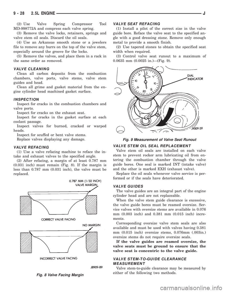
(2) After refacing, a margin of at least 0.787 mm
(0.031 inch) must remain (Fig. 8). If the margin is
less than 0.787 mm (0.031 inch), the valve must be
replaced.
VALVE SEAT REFACING
(1) Install a pilot of the correct size in the valve
guide bore. Reface the valve seat to the specified an-
gle with a good dressing stone. Remove only enough
metal to provide a smooth finish.
(2) Use tapered stones to obtain the specified seat
width when required.
(3) Control valve seat runout to a maximum of
0.0635 mm (0.0025 in.)Ð(Fig. 9).
VALVE STEM OIL SEAL REPLACEMENT
Valve stem oil seals are installed on each valve
stem to prevent rocker arm lubricating oil from en-
tering the combustion chamber through the valve
guide bores. One seal is marked INT (intake valve)
and the other is marked EXH (exhaust valve).
Replace the oil seals whenever valve service is per-
formed or if the seals have deteriorated.
VALVE GUIDES
The valve guides are an integral part of the engine
cylinder head and are not replaceable.
When the valve stem guide clearance is excessive,
the valve guide bores must be reamed oversize. Ser-
vice valves with oversize stems are available in 0.076
mm (0.003 inch) and 0.381 mm (0.015 inch) incre-
ments.
Corresponding oversize valve stem seals are also
available and must be used with valves having 0.381
mm (0.015 inch) oversize stems, 0.076mm (.003in.)
oversize stems do not require oversize seals.
If the valve guides are reamed oversize, the
valve seats must be ground to ensure that the
valve seat is concentric to the valve guide.
VALVE STEM-TO-GUIDE CLEARANCE
MEASUREMENT
Valve stem-to-guide clearance may be measured by
either of the following two methods.
Fig. 8 Valve Facing Margin
Fig. 9 Measurement of Valve Seat Runout
9 - 28 2.5L ENGINEJ
Page 1348 of 2158
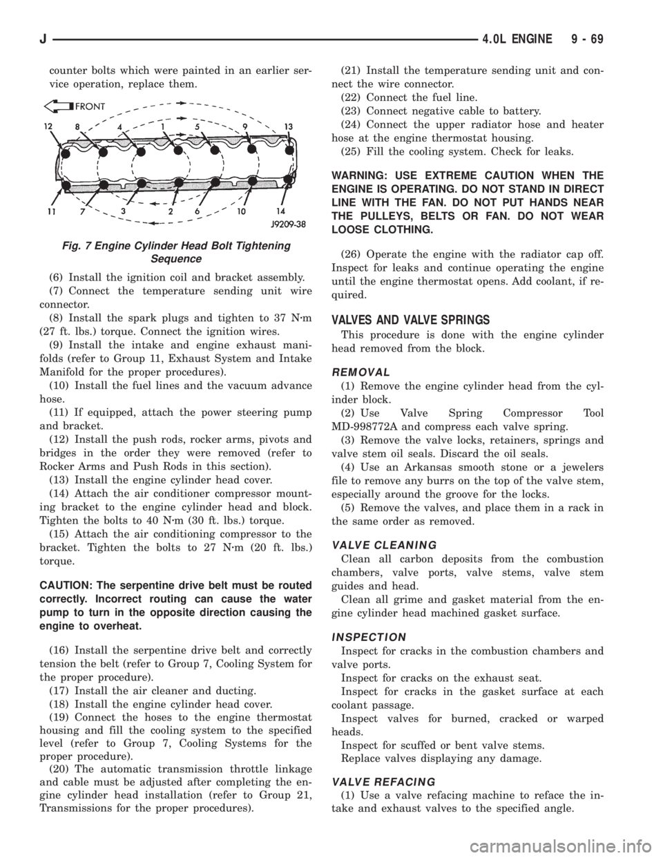
counter bolts which were painted in an earlier ser-
vice operation, replace them.
(6) Install the ignition coil and bracket assembly.
(7) Connect the temperature sending unit wire
connector.
(8) Install the spark plugs and tighten to 37 Nzm
(27 ft. lbs.) torque. Connect the ignition wires.
(9) Install the intake and engine exhaust mani-
folds (refer to Group 11, Exhaust System and Intake
Manifold for the proper procedures).
(10) Install the fuel lines and the vacuum advance
hose.
(11) If equipped, attach the power steering pump
and bracket.
(12) Install the push rods, rocker arms, pivots and
bridges in the order they were removed (refer to
Rocker Arms and Push Rods in this section).
(13) Install the engine cylinder head cover.
(14) Attach the air conditioner compressor mount-
ing bracket to the engine cylinder head and block.
Tighten the bolts to 40 Nzm (30 ft. lbs.) torque.
(15) Attach the air conditioning compressor to the
bracket. Tighten the bolts to 27 Nzm (20 ft. lbs.)
torque.
CAUTION: The serpentine drive belt must be routed
correctly. Incorrect routing can cause the water
pump to turn in the opposite direction causing the
engine to overheat.
(16) Install the serpentine drive belt and correctly
tension the belt (refer to Group 7, Cooling System for
the proper procedure).
(17) Install the air cleaner and ducting.
(18) Install the engine cylinder head cover.
(19) Connect the hoses to the engine thermostat
housing and fill the cooling system to the specified
level (refer to Group 7, Cooling Systems for the
proper procedure).
(20) The automatic transmission throttle linkage
and cable must be adjusted after completing the en-
gine cylinder head installation (refer to Group 21,
Transmissions for the proper procedures).(21) Install the temperature sending unit and con-
nect the wire connector.
(22) Connect the fuel line.
(23) Connect negative cable to battery.
(24) Connect the upper radiator hose and heater
hose at the engine thermostat housing.
(25) Fill the cooling system. Check for leaks.
WARNING: USE EXTREME CAUTION WHEN THE
ENGINE IS OPERATING. DO NOT STAND IN DIRECT
LINE WITH THE FAN. DO NOT PUT HANDS NEAR
THE PULLEYS, BELTS OR FAN. DO NOT WEAR
LOOSE CLOTHING.
(26) Operate the engine with the radiator cap off.
Inspect for leaks and continue operating the engine
until the engine thermostat opens. Add coolant, if re-
quired.
VALVES AND VALVE SPRINGS
This procedure is done with the engine cylinder
head removed from the block.
REMOVAL
(1) Remove the engine cylinder head from the cyl-
inder block.
(2) Use Valve Spring Compressor Tool
MD-998772A and compress each valve spring.
(3) Remove the valve locks, retainers, springs and
valve stem oil seals. Discard the oil seals.
(4) Use an Arkansas smooth stone or a jewelers
file to remove any burrs on the top of the valve stem,
especially around the groove for the locks.
(5) Remove the valves, and place them in a rack in
the same order as removed.
VALVE CLEANING
Clean all carbon deposits from the combustion
chambers, valve ports, valve stems, valve stem
guides and head.
Clean all grime and gasket material from the en-
gine cylinder head machined gasket surface.
INSPECTION
Inspect for cracks in the combustion chambers and
valve ports.
Inspect for cracks on the exhaust seat.
Inspect for cracks in the gasket surface at each
coolant passage.
Inspect valves for burned, cracked or warped
heads.
Inspect for scuffed or bent valve stems.
Replace valves displaying any damage.
VALVE REFACING
(1) Use a valve refacing machine to reface the in-
take and exhaust valves to the specified angle.
Fig. 7 Engine Cylinder Head Bolt Tightening
Sequence
J4.0L ENGINE 9 - 69
Page 1411 of 2158
codes are not displayed, the problem may be mechan-
ical rather than electronic.
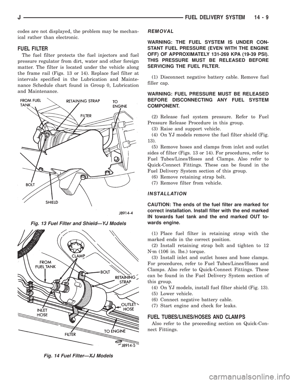
FUEL FILTER
The fuel filter protects the fuel injectors and fuel
pressure regulator from dirt, water and other foreign
matter. The filter is located under the vehicle along
the frame rail (Figs. 13 or 14). Replace fuel filter at
intervals specified in the Lubrication and Mainte-
nance Schedule chart found in Group 0, Lubrication
and Maintenance.
REMOVAL
WARNING: THE FUEL SYSTEM IS UNDER CON-
STANT FUEL PRESSURE (EVEN WITH THE ENGINE
OFF) OF APPROXIMATELY 131-269 KPA (19-39 PSI).
THIS PRESSURE MUST BE RELEASED BEFORE
SERVICING THE FUEL FILTER.
(1) Disconnect negative battery cable. Remove fuel
filler cap.
WARNING: FUEL PRESSURE MUST BE RELEASED
BEFORE DISCONNECTING ANY FUEL SYSTEM
COMPONENT.
(2) Release fuel system pressure. Refer to Fuel
Pressure Release Procedure in this group.
(3) Raise and support vehicle.
(4) On YJ models remove the fuel filter shield (Fig.
13).
(5) Remove hoses and clamps from inlet and outlet
sides of filter (Figs. 13 or 14). For procedures, refer to
Fuel Tubes/Lines/Hoses and Clamps. Also refer to
Quick-Connect Fittings. These can be found in the
Fuel Delivery System section of this group.
(6) Remove retaining strap bolt.
(7) Remove filter from vehicle.
INSTALLATION
CAUTION: The ends of the fuel filter are marked for
correct installation. Install filter with the end marked
IN towards fuel tank and the end marked OUT to-
wards engine.
(1) Place fuel filter in retaining strap with the
marked ends in the correct position.
(2) Install retaining strap bolt and tighten to 12
Nzm (106 in. lbs.) torque.
(3) Install inlet and outlet hoses and hose clamps.
For procedures, refer to Fuel Tubes/Lines/Hoses and
Clamps. Also refer to Quick-Connect Fittings. These
can be found in the Fuel Delivery System section of
this group.
(4) On YJ models, install fuel filter shield (Fig. 13).
(5) Lower vehicle.
(6) Connect negative battery cable.
(7) Start engine and check for leaks.
FUEL TUBES/LINES/HOSES AND CLAMPS
Also refer to the proceeding section on Quick-Con-
nect Fittings.
Fig. 13 Fuel Filter and ShieldÐYJ Models
Fig. 14 Fuel FilterÐXJ Models
JFUEL DELIVERY SYSTEM 14 - 9
Page 1430 of 2158
The throttle body has an air control passage that
provides air for the engine at idle (the throttle plate
is closed). The IAC motor pintle protrudes into the
air control passage and regulates air flow through it.
Based on various sensor inputs, the powertrain con-
trol module (PCM) adjusts engine idle speed by mov-
ing the IAC motor pintle in and out of the air control
passage. The IAC motor is positioned when the igni-
tion key is turned to the On position.
A (factory adjusted) set screw is used to mechani-
cally limit the position of the throttle body throttle
plate.Never attempt to adjust the engine idle
speed using this screw.All idle speed functions are
controlled by the PCM.
IGNITION COILÐPCM OUTPUT
System voltage is supplied to the ignition coil pos-
itive terminal. The powertrain control module (PCM)
operates the ignition coil.Base (initial) ignition
timing is not adjustable.The PCM adjusts ignition
timing to meet changing engine operating conditions.
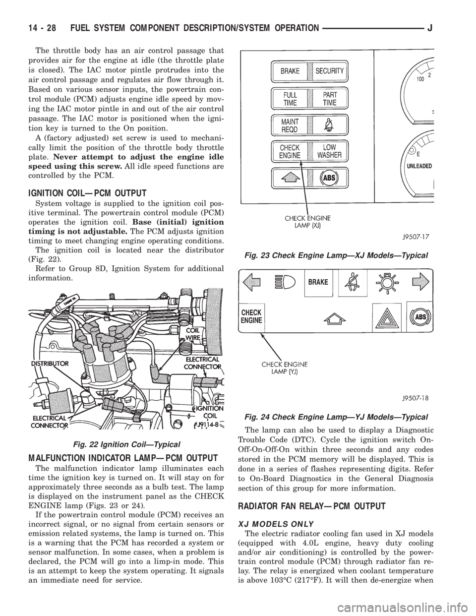
The ignition coil is located near the distributor
(Fig. 22).
Refer to Group 8D, Ignition System for additional
information.
MALFUNCTION INDICATOR LAMPÐPCM OUTPUT
The malfunction indicator lamp illuminates each
time the ignition key is turned on. It will stay on for
approximately three seconds as a bulb test. The lamp
is displayed on the instrument panel as the CHECK
ENGINE lamp (Figs. 23 or 24).
If the powertrain control module (PCM) receives an
incorrect signal, or no signal from certain sensors or
emission related systems, the lamp is turned on. This
is a warning that the PCM has recorded a system or
sensor malfunction. In some cases, when a problem is
declared, the PCM will go into a limp-in mode. This
is an attempt to keep the system operating. It signals
an immediate need for service.The lamp can also be used to display a Diagnostic
Trouble Code (DTC). Cycle the ignition switch On-
Off-On-Off-On within three seconds and any codes
stored in the PCM memory will be displayed. This is
done in a series of flashes representing digits. Refer
to On-Board Diagnostics in the General Diagnosis
section of this group for more information.
RADIATOR FAN RELAYÐPCM OUTPUT
XJ MODELS ONLY
The electric radiator cooling fan used in XJ models
(equipped with 4.0L engine, heavy duty cooling
and/or air conditioning) is controlled by the power-
train control module (PCM) through radiator fan re-
lay. The relay is energized when coolant temperature
is above 103ÉC (217ÉF). It will then de-energize when
Fig. 22 Ignition CoilÐTypical
Fig. 23 Check Engine LampÐXJ ModelsÐTypical
Fig. 24 Check Engine LampÐYJ ModelsÐTypical
14 - 28 FUEL SYSTEM COMPONENT DESCRIPTION/SYSTEM OPERATIONJ
Page 1443 of 2158
PCM SYSTEM SCHEMATICS
Powertrain control system schematics for the 2.5L
4-cylinder and 4.0L 6-cylinder engines are shown in
figures 29, 30, 31 and 32.
These schematics are displayed as a quick refer-
ence only. They are not intended to be all-inclusive.
Refer to the Wiring Diagrams section for detailed in-
formation.
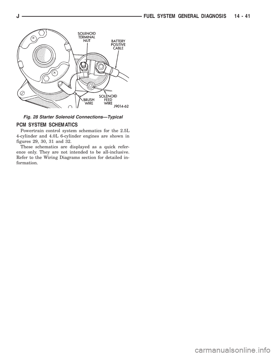
Fig. 28 Starter Solenoid ConnectionsÐTypical
JFUEL SYSTEM GENERAL DIAGNOSIS 14 - 41