1995 JEEP YJ change time
[x] Cancel search: change timePage 625 of 2158

INSTRUMENT CLUSTER
INDEX
page page
ABS Warning Lamp........................ 2
Brake Warning Lamp....................... 2
Charging System Indicator Lamp............... 3
Cluster Ground............................ 3
Diagram Index............................. 3
Engine Coolant Temperature Gauge............ 1
Engine Coolant Temperature Warning Lamp...... 1
Fuel Gauge.............................. 1
High-Beam Indicator Lamp................... 2
Instrument Cluster......................... 1Low Fuel Warning Lamp..................... 1
Low Washer Fluid Warning Lamp.............. 2
Malfunction Indicator Lamp (MIL)............... 2
Manual Transmission Up-Shift Lamp............ 2
Oil Pressure Gauge........................ 2
Oil Pressure Warning Lamp.................. 2
Seat Belt Indicator Warning Lamp.............. 2
Speedometer............................. 2
Tachometer.............................. 2
Turn Signal Indicator Lamps.................. 2
INSTRUMENT CLUSTER
The instrument cluster contains the gauges and
warning lamps. All gauges have magnetic move-
ments.
When the ignition switch is in the START or RUN
position, circuit A21 feeds circuit F87 through fuse 17
in the fuse block. Circuit A1 from fuse 6 in the Power
Distribution Center (PDC) supplies voltage to circuit
A21. Circuit A1 is HOT at all times.
Circuit F87 connects to the cluster connector to
power the gauges and to the telltale connector to
power the warning lamps.
Circuit E2 from fuse 19 in the fuse block feeds the
illumination lamps. Circuit E2 originates at the head-
lamp switch and continues through fuse 19. The
headlamp switch powers circuit E2 when the parking
lamps or headlamp are ON.
Circuit Z2 provides ground for the indicator lamps
and illumination lamps.
ENGINE COOLANT TEMPERATURE GAUGE
Circuit G20 connects the engine coolant tempera-
ture gauge to the engine coolant temperature sensor.
The sensor is a variable resistor and case grounded to
the engine. Circuit F87 connects to the instrument
cluster left connector and supplies voltage for the
gauge.
The gauge uses two coils. Current passing through
the coils creates a magnetic field. Position of the
gauge needle is controlled by the amount of current
passing through the coils to ground at the sensor.
ENGINE COOLANT TEMPERATURE WARNING
LAMP
Circuit G20 connects the engine coolant tempera-
ture warning lamp to the engine coolant temperature
switch. When the switch closes, battery voltage from
circuit F87 flows through the lamp to ground through
the switch on circuit G20. The engine coolant tem-
perature switch is case grounded to the engine. Cir-cuit F87 connects to the instrument cluster connector
and supplies voltage for the lamp.
Circuit G20 also connects to the warning lamp to
ground when the ignition switch is in the START
position. When the ignition switch is in the START
position, the lamp illuminates for a bulb test.
FUEL GAUGE
The fuel level sensor is a variable resistor. Circuit
G4 connects the fuel level sensor to the fuel gauge in
the instrument cluster. Circuit F87 from fuse 17 in
the fuse block supplies voltage to the fuel gauge. The
fuel level sensor draws voltage from circuit F87
through the fuel gauge on circuit G4. Circuit G4
connects to circuit 57 in the fuel pump module har-
ness. Circuit 57 connects to the fuel level sensor.
Circuit 99 in the fuel pump module harness con-
nects to circuit Z1. Circuit Z1 provides the ground
path for the fuel level sensor. The grounding point for
circuit Z1 is the left side of the cowl panel.
As current flows through the coils in the fuel gauge,
it creates a magnetic field. One of the coils in the
gauge receives fixed current. The other coil is con-
nected to the level sensor. The magnetic field controls
the position of the fuel gauge pointer.
The fuel level sensor contains a variable resistor. As
the position of the float arm on the fuel level sensor
changes, the resistor changes the current flow
through second coil in the fuel gauge. A change in
current flow alters the magnetic field in the fuel
gauge, which changes the pointer position.
LOW FUEL WARNING LAMP
Circuit G4 connects the fuel level sensor to the fuel
gauge. The low fuel level module at the rear of the
gauge monitors resistance in circuit G4. The low fuel
level module powers an light emitting diode (LED)
when the resistance in circuit G4 reaches a calibrated
level. The LED illuminates the Low Fuel indicator.
Refer to Group 8E for additional information.
J8W-40 INSTRUMENT CLUSTERÐXJ VEHICLES 8W - 40 - 1
Page 661 of 2158
HEATED REAR WINDOW
HEATED REAR WINDOW
The heated rear window relay supplies power to
heated rear window grid. Circuit F83 from fuse 8 in
the fuse 8 in the fuse block supplies power to the
heated rear window relay when the ignition switch is
in the ACCESSORY or RUN positions.
When the operator depresses the heated rear win-
dow switch, the contacts inside the switch momen-
tarily close and circuit C80 connects the switch to the
relay. This causes the relay to change state and com-
plete a circuit to energize the coil side of the relay
and start the relay timer.
Circuit F81 from fuse 18 in the fuse block supplies
voltage to the coil and contact sides of the relay. Cir-
cuit Z1 provides ground for the relay.
When the heated rear window relay energizes, the
contacts inside the relay close and connect circuit
F81 to circuit C15. Circuit C15 splices to the power
the heated rear window grid and the indicator lamp
in the heated rear window switch. Circuit Z1 pro-
vides ground for the heated rear window grid.
HELPFUL INFORMATION
²When the ignition switch is in the ACCESSORY or
RUN positions, it connects circuit A1 from fuse 6 in
the power distribution center (PDC) to circuit A48.
²Check for broken grid lines on the window.
²Check for a broken bus bar or disconnected leads
at the rear window.
²Check for a good ground.
DIAGRAM INDEX
Component Page
Fuse 6 (PDC)...........................8W-48-2
Fuse 7 (PDC)...........................8W-48-2
Fuse 8 (Fuse Block).......................8W-48-2
Fuse 18 (Fuse Block)......................8W-48-2
Ignition Switch..........................8W-48-2
Heated Rear Window Grid...................8W-48-3
Heated Rear Window Relay..................8W-48-2
Heated Rear Window Switch.................8W-48-2
J8W-48 HEATED REAR WINDOWÐXJ VEHICLES 8W - 48 - 1
Page 931 of 2158
HEATED REAR WINDOW
HEATED REAR WINDOW
The heated rear window relay supplies power to
heated rear window grid. Circuit F83 from fuse 14 in
the fuse block supplies power to the heated rear win-
dow relay when the ignition switch is in the ACCES-
SORY OR RUN positions.
When the operator depresses the heated rear win-
dow switch, the contacts inside the switch momen-
tarily close and circuit C80 connects the switch to the
relay. This causes the relay to change state and com-
plete a circuit to energize the coil side of the relay
and start the relay timer.
Circuit F82 from fuse 7 in the Power Distribution
Center (PDC) supplies voltage to the coil and contact
sides of the relay. Circuit Z1 provides ground for the
relay.
When the heated rear window relay energizes, the
contacts inside the relay close and connect circuit
F82 to circuit C15. Circuit C15 splices to the power
the heated rear window grid and the indicator lamp
in the heated rear window switch. Circuit Z1 pro-
vides ground for the heated rear window grid.
HELPFUL INFORMATION
²When the ignition switch is in the ACCESSORY or
RUN positions, it connects circuit A1 from fuse 11 in
the power distribution center (PDC) to circuit A48.
²Check for broken grid lines on the window.
²Check for a broken bus bar or disconnected leads
at the rear window.
²Check for a good ground.
DIAGRAM INDEX
Component Page
Fuse 2 (Fuse Block).......................8W-48-2
Fuse 6 (PDC)...........................8W-48-2
Fuse 7 (PDC)...........................8W-48-2
Fuse 14 (Fuse Block)......................8W-48-2
Ignition Switch..........................8W-48-2
Heated Rear Window Grid...................8W-48-3
Heated Rear Window Relay..................8W-48-2
Heated Rear Window Switch.................8W-48-2
J8W-48 HEATED REAR WINDOWÐXJ-RHD 8W - 48 - 1
Page 1124 of 2158
²Circuit K60 connects to cavity 60 of the PCM.
VEHICLE SPEED SENSOR
Circuit K7 supplies 8 volts from the Powertrain
Control Module (PCM) to the vehicle speed sensor.
The K7 circuit connects to cavity 7 of the PCM.
Circuit G7 from the vehicle speed sensor provides
an input signal to the PCM. The G7 circuit connects
to cavity 47 of the PCM.
The PCM provides a ground for the vehicle speed
sensor signal (circuit G7) through circuit K4. Circuit
K4 connects to cavity 4 of the PCM.
HELPFUL INFORMATION
²Circuit G7 splices to the speedometer, and Day-
time Running Lamp module (DRL).
²Circuit K7 splices to supply 8 volts to the camshaft
position sensor and crankshaft position sensor.
Circuit K4 splices to supply ground for the signals
from the following:
²Heated oxygen sensor
²Camshaft position sensor
²Crankshaft position sensor
²Throttle position sensor
²Manifold absolute pressure sensor
²Engine coolant temperature sensor
²Intake air temperature sensor
HEATED OXYGEN SENSOR
When the Automatic Shut Down (ASD) relay con-
tacts close, they connect circuits A14 and A142. Cir-
cuit A142 splices to supply voltage to the heated
oxygen sensor.
Circuit K41 delivers the signal from the heated ox-
ygen sensor to the Powertrain Control Module
(PCM). Circuit K41 connects to cavity 41 of the PCM.
The PCM provides a ground for the heated oxygen
sensor signal (circuit K41) through circuit K4. Circuit
K4 connects to cavity 4 of the PCM connector.
Circuit Z1 provides a ground for the heater circuit
in the sensor. Circuit Z1 terminates at the rear of the
engine.
HELPFUL INFORMATION
²Along with supplying voltage to the ASD relay
contacts, circuit A14 supplies voltage to the contact
side of the fuel pump relay.
²Circuit A142 splices to supply voltage to the fuel
injectors, ignition coil, and heated oxygen sensor.
Circuit K4 splices to supply ground for the signals
from the following:
²Camshaft position sensor
²Crankshaft position sensor
²Intake air temperature sensor
²Throttle position sensor
²Manifold absolute pressure sensor
²Engine coolant temperature sensor
²Vehicle speed sensor
CAMSHAFT POSITION SENSOR
The Powertrain Control Module (PCM) supplies 8
volts to the camshaft position sensor (in distributor)
on circuit K7. Circuit K7 connects to cavity 7 of the
PCM.
The PCM receives the camshaft position sensor sig-
nal on circuit K44. Circuit K44 connects to cavity 44
of the PCM.
The PCM provides a ground for the camshaft posi-
tion sensor signal (circuit K44) through circuit K4.
Circuit K4 connects to cavity 4 of the PCM.
HELPFUL INFORMATION
²Circuit K7 splices to supply 8 volts to the crank-
shaft position sensor and the vehicle speed sensor.
Circuit K4 splices to supply ground for the signals
from the following:
²Heated oxygen sensor
²Crankshaft position sensor
²Intake air temperature sensor
²Throttle position sensor
²Manifold absolute pressure sensor
²Engine coolant temperature sensor
²Vehicle speed sensor
CRANKSHAFT POSITION SENSOR
The Powertrain Control Module (PCM) supplies 8
volts to the crankshaft position sensor on circuit K7.
Circuit K7 connects to cavity 7 of the PCM.
The PCM receives the crankshaft position sensor
signal on circuit K24. Circuit K24 connects to cavity
24 of the PCM.
The PCM provides a ground for the crankshaft po-
sition sensor (circuit K24) through circuit K4. Circuit
K4 connects to cavity 4 of the PCM.
HELPFUL INFORMATION
²Circuit K7 splices to supply 8 volts to the crank-
shaft position sensor and the vehicle speed sensor.
Circuit K4 splices to supply ground for the signals
from the following:
²Heated oxygen sensor
²Camshaft position sensor
²Intake air temperature sensor
²Throttle position sensor
²Manifold absolute pressure sensor
²Engine coolant temperature sensor
²Vehicle speed sensor
ENGINE COOLANT TEMPERATURE SENSOR
The engine coolant temperature sensor provides an
input to the Powertrain Control Module (PCM) on
circuit K2. From circuit K2, the engine coolant tem-
perature sensor draws up to 5 volts from the PCM.
The sensor is a variable resistor. As coolant temper-
ature changes, the resistance in the sensor changes,
causing a change in current draw. The K2 circuit
connects to cavity 2 of the PCM.
J8W-30 FUEL/IGNITIONÐYJ VEHICLES 8W - 30 - 3
Page 1186 of 2158
HEATED REAR WINDOW
HEATED REAR WINDOW
The heated rear window relay supplies power to
heated rear window grid. When the operator presses
the heated rear window switch, the contacts inside
the switch momentarily close and circuit C16 con-
nects the relay timer to ground on circuit Z1. This
causes the relay to change state and complete a cir-
cuit to energize the coil side of the relay and start
the relay timer. Circuit G5 from fuse 9 in the fuse
block supplies voltage to the coil side of the relay.
Circuit Z1 provides ground for the relay.
When the heated rear window relay energizes, the
contacts inside the relay close and connect circuit
F32 to circuit C15. Fuse 3 in the fuse block protects
circuit F32.
Circuit C15 is double crimped at the heated rear
window relay. One branch of circuit C15 powers the
indicator lamp in the heated rear window switch.
The other branch of circuit C15 powers the heated
rear window grid. Circuit Z1 provides ground for the
heated rear window grid.
At the rear window grid, circuits C15 and Z1 pass
through lift gate support struts.
HELPFUL INFORMATION
²When the ignition switch is in the START or RUN
positions, it connects circuit A1 from fuse 4 in the
Power Distribution Center (PDC) to circuit A21. Cir-
cuit A21 supplies battery voltage to the fuse block
bus bar that powers circuit G5 through the fuse in
cavity 9.
²Circuit A6 from PDC fuse 3 supplies battery volt-
age to the fuse block bus bar that feeds fuse 3 and
circuit F32. Check fuse 3 in the PDC and fuse 3 in
the fuse block.
²Check for broken grid lines on the window.
²Check for a broken bus bar or disconnected leads
at the rear window.
²Check for a good ground.
DIAGRAM INDEX
Component Page
Fuse 3 (PDC)...........................8W-48-2
Fuse 4 (PDC)...........................8W-48-2
Fuse 6 (Fuse Block).......................8W-48-2
Fuse 9 (Fuse Block).......................8W-48-2
Heated Rear Window Relay..................8W-48-2
Heated Rear Window Grid...................8W-48-3
Heated Rear Window Switch.................8W-48-3
J8W-48 HEATED REAR WINDOWÐYJ VEHICLES 8W - 48 - 1
Page 1304 of 2158
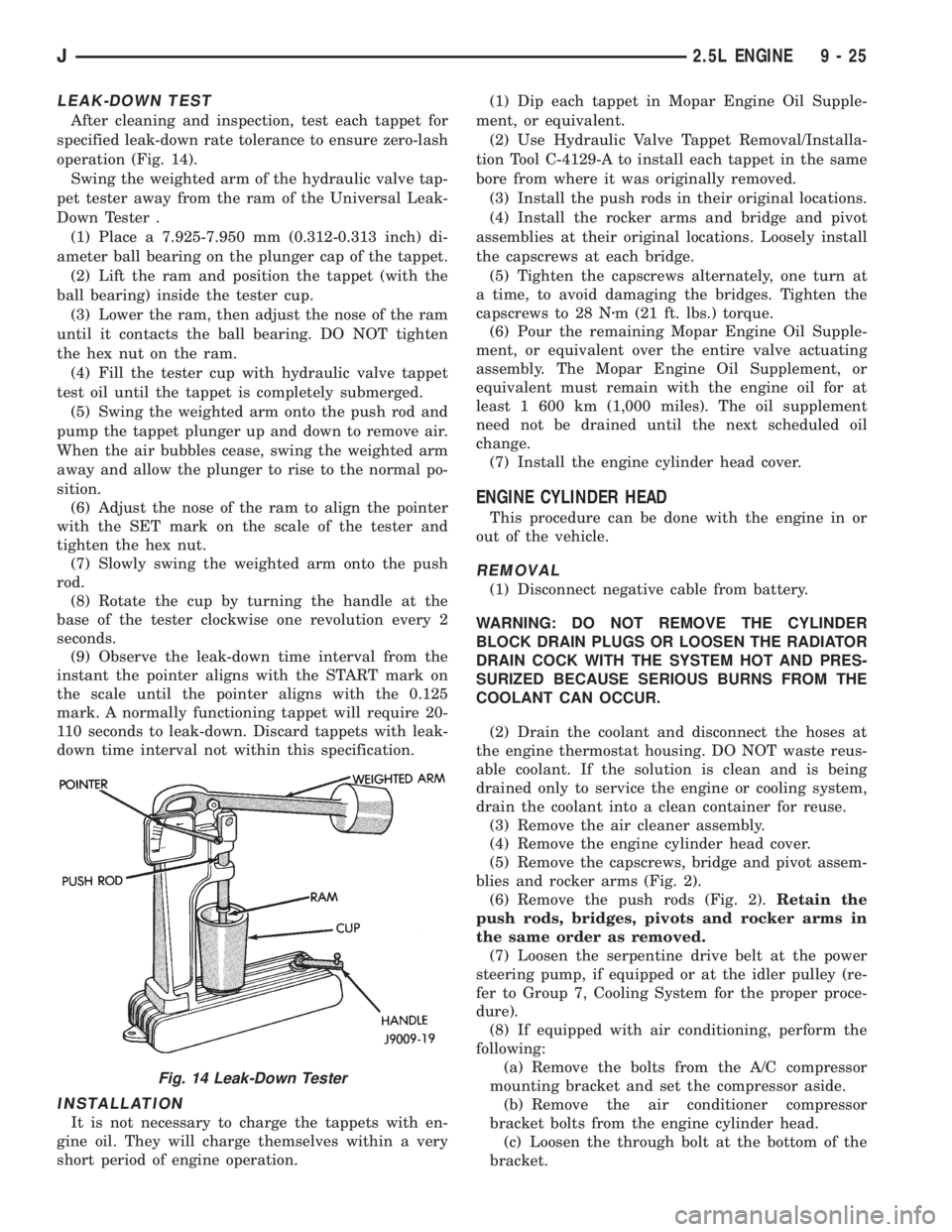
LEAK-DOWN TEST
After cleaning and inspection, test each tappet for
specified leak-down rate tolerance to ensure zero-lash
operation (Fig. 14).
Swing the weighted arm of the hydraulic valve tap-
pet tester away from the ram of the Universal Leak-
Down Tester .
(1) Place a 7.925-7.950 mm (0.312-0.313 inch) di-
ameter ball bearing on the plunger cap of the tappet.
(2) Lift the ram and position the tappet (with the
ball bearing) inside the tester cup.
(3) Lower the ram, then adjust the nose of the ram
until it contacts the ball bearing. DO NOT tighten
the hex nut on the ram.
(4) Fill the tester cup with hydraulic valve tappet
test oil until the tappet is completely submerged.
(5) Swing the weighted arm onto the push rod and
pump the tappet plunger up and down to remove air.
When the air bubbles cease, swing the weighted arm
away and allow the plunger to rise to the normal po-
sition.
(6) Adjust the nose of the ram to align the pointer
with the SET mark on the scale of the tester and
tighten the hex nut.
(7) Slowly swing the weighted arm onto the push
rod.
(8) Rotate the cup by turning the handle at the
base of the tester clockwise one revolution every 2
seconds.
(9) Observe the leak-down time interval from the
instant the pointer aligns with the START mark on
the scale until the pointer aligns with the 0.125
mark. A normally functioning tappet will require 20-
110 seconds to leak-down. Discard tappets with leak-
down time interval not within this specification.
INSTALLATION
It is not necessary to charge the tappets with en-
gine oil. They will charge themselves within a very
short period of engine operation.(1) Dip each tappet in Mopar Engine Oil Supple-
ment, or equivalent.
(2) Use Hydraulic Valve Tappet Removal/Installa-
tion Tool C-4129-A to install each tappet in the same
bore from where it was originally removed.
(3) Install the push rods in their original locations.
(4) Install the rocker arms and bridge and pivot
assemblies at their original locations. Loosely install
the capscrews at each bridge.
(5) Tighten the capscrews alternately, one turn at
a time, to avoid damaging the bridges. Tighten the
capscrews to 28 Nzm (21 ft. lbs.) torque.
(6) Pour the remaining Mopar Engine Oil Supple-
ment, or equivalent over the entire valve actuating
assembly. The Mopar Engine Oil Supplement, or
equivalent must remain with the engine oil for at
least 1 600 km (1,000 miles). The oil supplement
need not be drained until the next scheduled oil
change.
(7) Install the engine cylinder head cover.
ENGINE CYLINDER HEAD
This procedure can be done with the engine in or
out of the vehicle.
REMOVAL
(1) Disconnect negative cable from battery.
WARNING: DO NOT REMOVE THE CYLINDER
BLOCK DRAIN PLUGS OR LOOSEN THE RADIATOR
DRAIN COCK WITH THE SYSTEM HOT AND PRES-
SURIZED BECAUSE SERIOUS BURNS FROM THE
COOLANT CAN OCCUR.
(2) Drain the coolant and disconnect the hoses at
the engine thermostat housing. DO NOT waste reus-
able coolant. If the solution is clean and is being
drained only to service the engine or cooling system,
drain the coolant into a clean container for reuse.
(3) Remove the air cleaner assembly.
(4) Remove the engine cylinder head cover.
(5) Remove the capscrews, bridge and pivot assem-
blies and rocker arms (Fig. 2).
(6) Remove the push rods (Fig. 2).Retain the
push rods, bridges, pivots and rocker arms in
the same order as removed.
(7) Loosen the serpentine drive belt at the power
steering pump, if equipped or at the idler pulley (re-
fer to Group 7, Cooling System for the proper proce-
dure).
(8) If equipped with air conditioning, perform the
following:
(a) Remove the bolts from the A/C compressor
mounting bracket and set the compressor aside.
(b) Remove the air conditioner compressor
bracket bolts from the engine cylinder head.
(c) Loosen the through bolt at the bottom of the
bracket.
Fig. 14 Leak-Down Tester
J2.5L ENGINE 9 - 25
Page 1346 of 2158
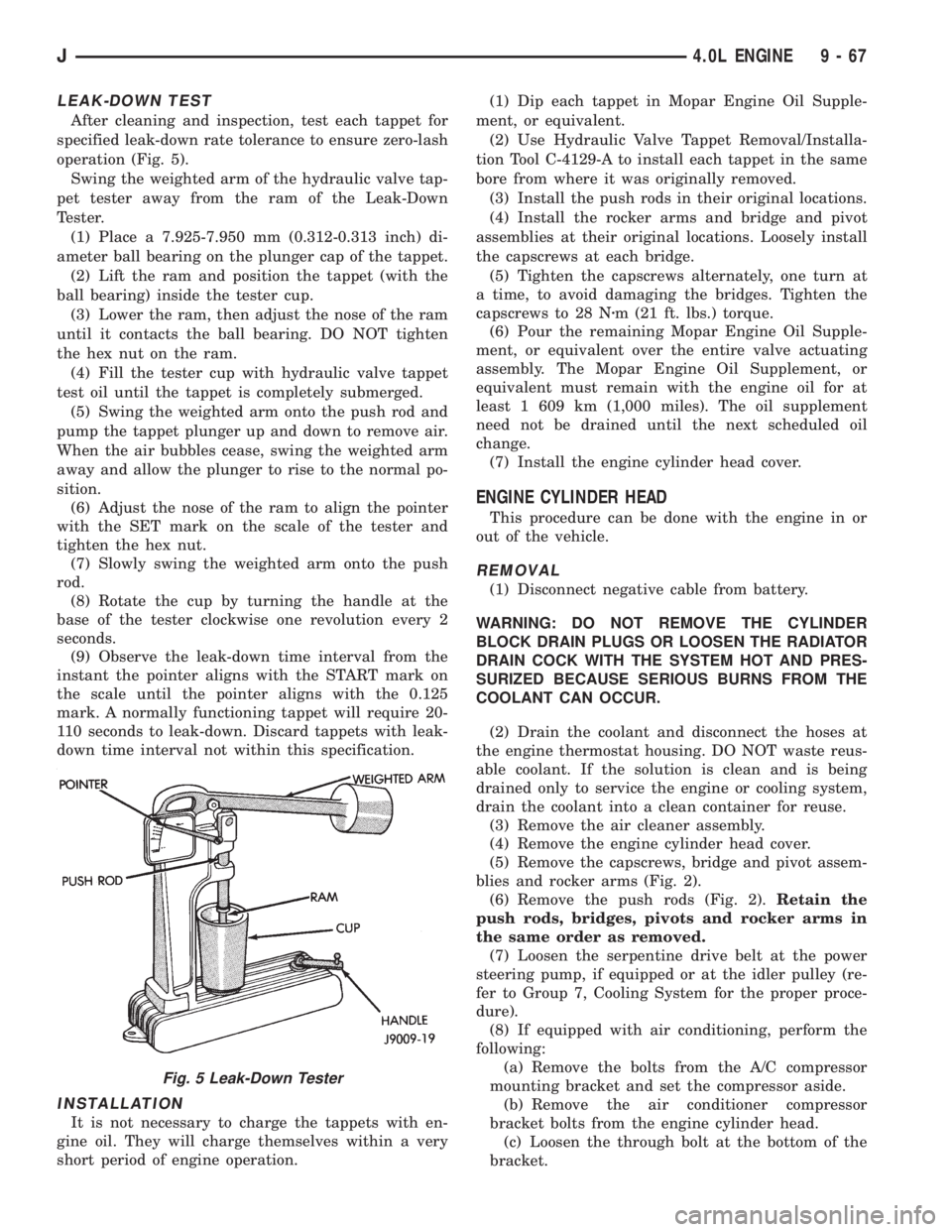
LEAK-DOWN TEST
After cleaning and inspection, test each tappet for
specified leak-down rate tolerance to ensure zero-lash
operation (Fig. 5).
Swing the weighted arm of the hydraulic valve tap-
pet tester away from the ram of the Leak-Down
Tester.
(1) Place a 7.925-7.950 mm (0.312-0.313 inch) di-
ameter ball bearing on the plunger cap of the tappet.
(2) Lift the ram and position the tappet (with the
ball bearing) inside the tester cup.
(3) Lower the ram, then adjust the nose of the ram
until it contacts the ball bearing. DO NOT tighten
the hex nut on the ram.
(4) Fill the tester cup with hydraulic valve tappet
test oil until the tappet is completely submerged.
(5) Swing the weighted arm onto the push rod and
pump the tappet plunger up and down to remove air.
When the air bubbles cease, swing the weighted arm
away and allow the plunger to rise to the normal po-
sition.
(6) Adjust the nose of the ram to align the pointer
with the SET mark on the scale of the tester and
tighten the hex nut.
(7) Slowly swing the weighted arm onto the push
rod.
(8) Rotate the cup by turning the handle at the
base of the tester clockwise one revolution every 2
seconds.
(9) Observe the leak-down time interval from the
instant the pointer aligns with the START mark on
the scale until the pointer aligns with the 0.125
mark. A normally functioning tappet will require 20-
110 seconds to leak-down. Discard tappets with leak-
down time interval not within this specification.
INSTALLATION
It is not necessary to charge the tappets with en-
gine oil. They will charge themselves within a very
short period of engine operation.(1) Dip each tappet in Mopar Engine Oil Supple-
ment, or equivalent.
(2) Use Hydraulic Valve Tappet Removal/Installa-
tion Tool C-4129-A to install each tappet in the same
bore from where it was originally removed.
(3) Install the push rods in their original locations.
(4) Install the rocker arms and bridge and pivot
assemblies at their original locations. Loosely install
the capscrews at each bridge.
(5) Tighten the capscrews alternately, one turn at
a time, to avoid damaging the bridges. Tighten the
capscrews to 28 Nzm (21 ft. lbs.) torque.
(6) Pour the remaining Mopar Engine Oil Supple-
ment, or equivalent over the entire valve actuating
assembly. The Mopar Engine Oil Supplement, or
equivalent must remain with the engine oil for at
least 1 609 km (1,000 miles). The oil supplement
need not be drained until the next scheduled oil
change.
(7) Install the engine cylinder head cover.
ENGINE CYLINDER HEAD
This procedure can be done with the engine in or
out of the vehicle.
REMOVAL
(1) Disconnect negative cable from battery.
WARNING: DO NOT REMOVE THE CYLINDER
BLOCK DRAIN PLUGS OR LOOSEN THE RADIATOR
DRAIN COCK WITH THE SYSTEM HOT AND PRES-
SURIZED BECAUSE SERIOUS BURNS FROM THE
COOLANT CAN OCCUR.
(2) Drain the coolant and disconnect the hoses at
the engine thermostat housing. DO NOT waste reus-
able coolant. If the solution is clean and is being
drained only to service the engine or cooling system,
drain the coolant into a clean container for reuse.
(3) Remove the air cleaner assembly.
(4) Remove the engine cylinder head cover.
(5) Remove the capscrews, bridge and pivot assem-
blies and rocker arms (Fig. 2).
(6) Remove the push rods (Fig. 2).Retain the
push rods, bridges, pivots and rocker arms in
the same order as removed.
(7) Loosen the serpentine drive belt at the power
steering pump, if equipped or at the idler pulley (re-
fer to Group 7, Cooling System for the proper proce-
dure).
(8) If equipped with air conditioning, perform the
following:
(a) Remove the bolts from the A/C compressor
mounting bracket and set the compressor aside.
(b) Remove the air conditioner compressor
bracket bolts from the engine cylinder head.
(c) Loosen the through bolt at the bottom of the
bracket.
Fig. 5 Leak-Down Tester
J4.0L ENGINE 9 - 67
Page 1354 of 2158
INSPECTION
Inspect the cam lobes for wear.
Inspect the bearing journals for uneven wear pat-
tern or finish.
Inspect the bearings for wear.
Inspect the distributor drive gear for wear.
If the camshaft appears to have been rubbing
against the timing case cover, examine the oil pres-
sure relief holes in the rear cam journal. The oil
pressure relief holes must be free of debris.
INSTALLATION
(1) Lubricate the camshaft with Mopar Engine Oil
Supplement, or equivalent.
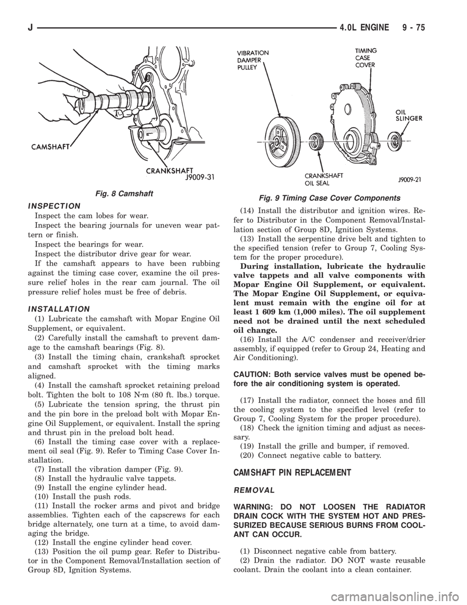
(2) Carefully install the camshaft to prevent dam-
age to the camshaft bearings (Fig. 8).
(3) Install the timing chain, crankshaft sprocket
and camshaft sprocket with the timing marks
aligned.
(4) Install the camshaft sprocket retaining preload
bolt. Tighten the bolt to 108 Nzm (80 ft. lbs.) torque.
(5) Lubricate the tension spring, the thrust pin
and the pin bore in the preload bolt with Mopar En-
gine Oil Supplement, or equivalent. Install the spring
and thrust pin in the preload bolt head.
(6) Install the timing case cover with a replace-
ment oil seal (Fig. 9). Refer to Timing Case Cover In-
stallation.
(7) Install the vibration damper (Fig. 9).
(8) Install the hydraulic valve tappets.
(9) Install the engine cylinder head.
(10) Install the push rods.
(11) Install the rocker arms and pivot and bridge
assemblies. Tighten each of the capscrews for each
bridge alternately, one turn at a time, to avoid dam-
aging the bridge.
(12) Install the engine cylinder head cover.
(13) Position the oil pump gear. Refer to Distribu-
tor in the Component Removal/Installation section of
Group 8D, Ignition Systems.(14) Install the distributor and ignition wires. Re-
fer to Distributor in the Component Removal/Instal-
lation section of Group 8D, Ignition Systems.
(13) Install the serpentine drive belt and tighten to
the specified tension (refer to Group 7, Cooling Sys-
tem for the proper procedure).
During installation, lubricate the hydraulic
valve tappets and all valve components with
Mopar Engine Oil Supplement, or equivalent.
The Mopar Engine Oil Supplement, or equiva-
lent must remain with the engine oil for at
least 1 609 km (1,000 miles). The oil supplement
need not be drained until the next scheduled
oil change.
(16) Install the A/C condenser and receiver/drier
assembly, if equipped (refer to Group 24, Heating and
Air Conditioning).
CAUTION: Both service valves must be opened be-
fore the air conditioning system is operated.
(17) Install the radiator, connect the hoses and fill
the cooling system to the specified level (refer to
Group 7, Cooling System for the proper procedure).
(18) Check the ignition timing and adjust as neces-
sary.
(19) Install the grille and bumper, if removed.
(20) Connect negative cable to battery.
CAMSHAFT PIN REPLACEMENT
REMOVAL
WARNING: DO NOT LOOSEN THE RADIATOR
DRAIN COCK WITH THE SYSTEM HOT AND PRES-
SURIZED BECAUSE SERIOUS BURNS FROM COOL-
ANT CAN OCCUR.
(1) Disconnect negative cable from battery.
(2) Drain the radiator. DO NOT waste reusable
coolant. Drain the coolant into a clean container.
Fig. 9 Timing Case Cover ComponentsFig. 8 Camshaft
J4.0L ENGINE 9 - 75