1995 JEEP YJ torque
[x] Cancel search: torquePage 1671 of 2158
Inspection
Check the sprag shaft for scores and for free move-
ment in the housing and sprag.
Check the sprag and control rod springs for loss of
tension or distortion. Check the square lug on the
sprag for broken edges. Check the lugs on the gover-
nor support (park gear) for broken edges. Replace
any park lock components that are worn or damaged.
Check the knob on the end of the control rod for
nicks, burrs and free turning. Replace the rod if the
knob is grooved, or worn, or if the rod is bent. The
park lock rods used in Chrysler 3-speed transmis-
sions are different lengths. If the rod must be re-
placed, be sure to install the correct length and
shape rod.
COMPONENT INSTALLATION
(1) Install park lock rod on valve body.
(2) Install reaction plug and pin assembly in the
housing and install the snap ring.
(3) Position sprag and spring in housing and in-
stall sprag shaft. Be sure square lug on sprag is fac-
ing park gear and that spring is positioned so it
moves sprag away from park gear.
(4) Install valve body.
(5) Install adapter housing and transfer case.
PARK/NEUTRAL POSITION SWITCH SERVICE
The starter feed circuit of the switch is through the
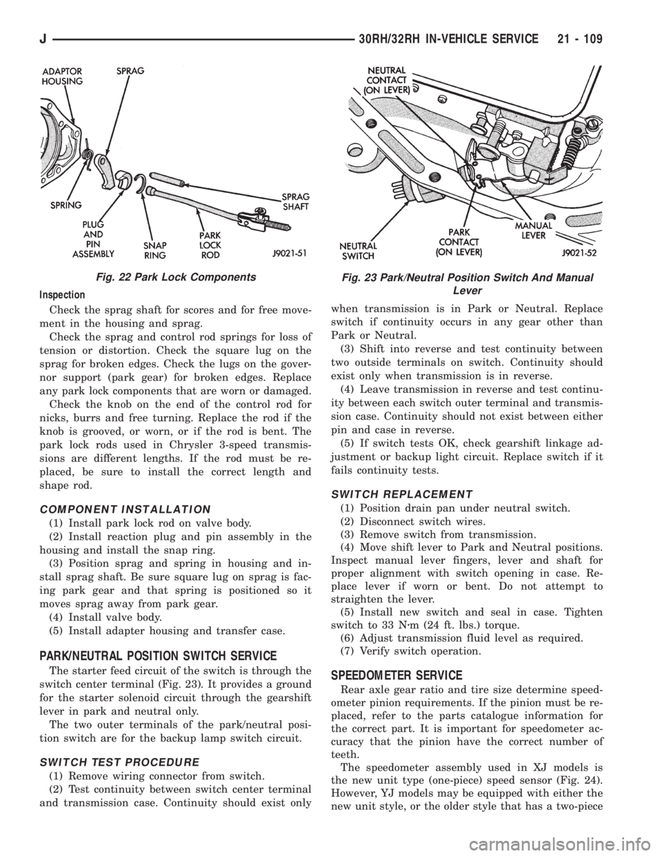
switch center terminal (Fig. 23). It provides a ground
for the starter solenoid circuit through the gearshift
lever in park and neutral only.
The two outer terminals of the park/neutral posi-
tion switch are for the backup lamp switch circuit.
SWITCH TEST PROCEDURE
(1) Remove wiring connector from switch.
(2) Test continuity between switch center terminal
and transmission case. Continuity should exist onlywhen transmission is in Park or Neutral. Replace
switch if continuity occurs in any gear other than
Park or Neutral.
(3) Shift into reverse and test continuity between
two outside terminals on switch. Continuity should
exist only when transmission is in reverse.
(4) Leave transmission in reverse and test continu-
ity between each switch outer terminal and transmis-
sion case. Continuity should not exist between either
pin and case in reverse.
(5) If switch tests OK, check gearshift linkage ad-
justment or backup light circuit. Replace switch if it
fails continuity tests.
SWITCH REPLACEMENT
(1) Position drain pan under neutral switch.
(2) Disconnect switch wires.
(3) Remove switch from transmission.
(4) Move shift lever to Park and Neutral positions.
Inspect manual lever fingers, lever and shaft for
proper alignment with switch opening in case. Re-
place lever if worn or bent. Do not attempt to
straighten the lever.
(5) Install new switch and seal in case. Tighten
switch to 33 Nzm (24 ft. lbs.) torque.
(6) Adjust transmission fluid level as required.
(7) Verify switch operation.
SPEEDOMETER SERVICE
Rear axle gear ratio and tire size determine speed-
ometer pinion requirements. If the pinion must be re-
placed, refer to the parts catalogue information for
the correct part. It is important for speedometer ac-
curacy that the pinion have the correct number of
teeth.
The speedometer assembly used in XJ models is
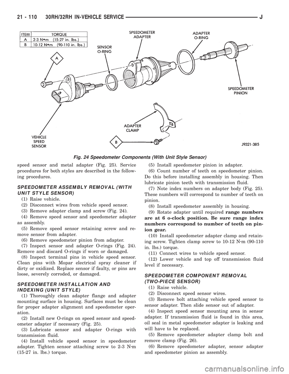
the new unit type (one-piece) speed sensor (Fig. 24).
However, YJ models may be equipped with either the
new unit style, or the older style that has a two-piece
Fig. 22 Park Lock ComponentsFig. 23 Park/Neutral Position Switch And Manual
Lever
J30RH/32RH IN-VEHICLE SERVICE 21 - 109
Page 1672 of 2158
speed sensor and metal adapter (Fig. 25). Service
procedures for both styles are described in the follow-
ing procedures.
SPEEDOMETER ASSEMBLY REMOVAL (WITH
UNIT STYLE SENSOR)
(1) Raise vehicle.
(2) Disconnect wires from vehicle speed sensor.
(3) Remove adapter clamp and screw (Fig. 24).
(4) Remove speed sensor and speedometer adapter
as assembly.
(5) Remove speed sensor retaining screw and re-
move sensor from adapter.
(6) Remove speedometer pinion from adapter.
(7) Inspect sensor and adapter O-rings (Fig. 24).
Remove and discard O-rings if worn or damaged.
(8) Inspect terminal pins in vehicle speed sensor.
Clean pins with Mopar electrical spray cleaner if
dirty or oxidized. Replace sensor if faulty, or pins are
loose, severely corroded, or damaged.
SPEEDOMETER INSTALLATION AND
INDEXING (UNIT STYLE)
(1) Thoroughly clean adapter flange and adapter
mounting surface in housing. Surfaces must be clean
for proper adapter alignment and speedometer oper-
ation.
(2) Install new O-rings on speed sensor and speed-
ometer adapter if necessary (Fig. 25).
(3) Lubricate sensor and adapter O-rings with
transmission fluid.
(4) Install vehicle speed sensor in speedometer
adapter. Tighten sensor attaching screw to 2-3 Nzm
(15-27 in. lbs.) torque.(5) Install speedometer pinion in adapter.
(6) Count number of teeth on speedometer pinion.
Do this before installing assembly in housing. Then
lubricate pinion teeth with transmission fluid.
(7) Note index numbers on adapter body (Fig. 25).
These numbers will correspond to number of teeth on
pinion.
(8) Install speedometer assembly in housing.
(9) Rotate adapter until requiredrange numbers
are at 6 o-clock position. Be sure range index
numbers correspond to number of teeth on pin-
ion gear.
(10) Install speedometer adapter clamp and retain-
ing screw. Tighten clamp screw to 10-12 Nzm (90-110
in. lbs.) torque.
(11) Connect wires to vehicle speed sensor.
(12) Lower vehicle and top off transmission fluid
level if necessary.
SPEEDOMETER COMPONENT REMOVAL
(TWO-PIECE SENSOR)
(1) Raise vehicle.
(2) Disconnect speed sensor wires.
(3) Remove bolt attaching vehicle speed sensor to
sensor adapter. Then slide sensor out of adapter.
(4) Inspect speed sensor mounting area in sensor
adapter. If transmission fluid is found in this area,
oil seal in metal speedometer adapter is leaking and
will have to be replaced.
(5) Remove speedometer adapter clamp bolt and
remove clamp (Fig. 26).
(6) Remove speedometer adapter, sensor adapter
and speedometer pinion as assembly.
Fig. 24 Speedometer Components (With Unit Style Sensor)
21 - 110 30RH/32RH IN-VEHICLE SERVICEJ
Page 1673 of 2158
SPEEDOMETER COMPONENT INSTALLATION
AND INDEXING (TWO-PIECE SENSOR)
(1) Replace speedometer O-ring if cut, torn, or
worn.
(2) If oil seal in metal speedometer adapter needs
replacement, remove old seal with pointed tool. Then
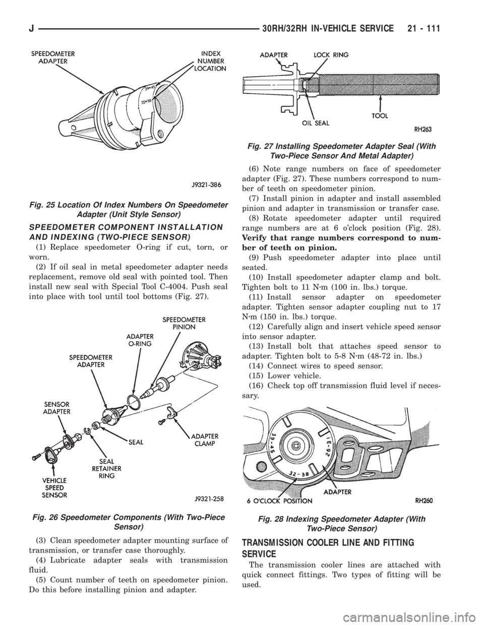
install new seal with Special Tool C-4004. Push seal
into place with tool until tool bottoms (Fig. 27).
(3) Clean speedometer adapter mounting surface of
transmission, or transfer case thoroughly.
(4) Lubricate adapter seals with transmission
fluid.
(5) Count number of teeth on speedometer pinion.
Do this before installing pinion and adapter.(6) Note range numbers on face of speedometer
adapter (Fig. 27). These numbers correspond to num-
ber of teeth on speedometer pinion.
(7) Install pinion in adapter and install assembled
pinion and adapter in transmission or transfer case.
(8) Rotate speedometer adapter until required
range numbers are at 6 o'clock position (Fig. 28).
Verify that range numbers correspond to num-
ber of teeth on pinion.
(9) Push speedometer adapter into place until
seated.
(10) Install speedometer adapter clamp and bolt.
Tighten bolt to 11 Nzm (100 in. lbs.) torque.
(11) Install sensor adapter on speedometer
adapter. Tighten sensor adapter coupling nut to 17
Nzm (150 in. lbs.) torque.
(12) Carefully align and insert vehicle speed sensor
into sensor adapter.
(13) Install bolt that attaches speed sensor to
adapter. Tighten bolt to 5-8 Nzm (48-72 in. lbs.)
(14) Connect wires to speed sensor.
(15) Lower vehicle.
(16) Check top off transmission fluid level if neces-
sary.
TRANSMISSION COOLER LINE AND FITTING
SERVICE
The transmission cooler lines are attached with
quick connect fittings. Two types of fitting will be
used.
Fig. 25 Location Of Index Numbers On Speedometer
Adapter (Unit Style Sensor)
Fig. 26 Speedometer Components (With Two-Piece
Sensor)
Fig. 27 Installing Speedometer Adapter Seal (With
Two-Piece Sensor And Metal Adapter)
Fig. 28 Indexing Speedometer Adapter (With
Two-Piece Sensor)
J30RH/32RH IN-VEHICLE SERVICE 21 - 111
Page 1678 of 2158
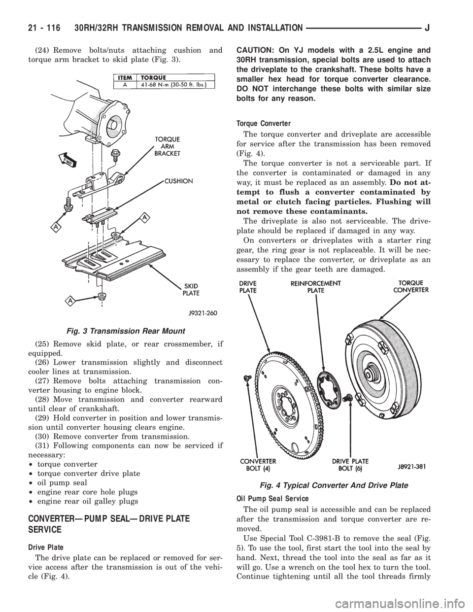
(24) Remove bolts/nuts attaching cushion and
torque arm bracket to skid plate (Fig. 3).
(25) Remove skid plate, or rear crossmember, if
equipped.
(26) Lower transmission slightly and disconnect
cooler lines at transmission.
(27) Remove bolts attaching transmission con-
verter housing to engine block.
(28) Move transmission and converter rearward
until clear of crankshaft.
(29) Hold converter in position and lower transmis-
sion until converter housing clears engine.
(30) Remove converter from transmission.
(31) Following components can now be serviced if
necessary:
²torque converter
²torque converter drive plate
²oil pump seal
²engine rear core hole plugs
²engine rear oil galley plugs
CONVERTERÐPUMP SEALÐDRIVE PLATE
SERVICE
Drive Plate
The drive plate can be replaced or removed for ser-
vice access after the transmission is out of the vehi-
cle (Fig. 4).CAUTION: On YJ models with a 2.5L engine and
30RH transmission, special bolts are used to attach
the driveplate to the crankshaft. These bolts have a
smaller hex head for torque converter clearance.
DO NOT interchange these bolts with similar size
bolts for any reason.
Torque Converter
The torque converter and driveplate are accessible
for service after the transmission has been removed
(Fig. 4).
The torque converter is not a serviceable part. If
the converter is contaminated or damaged in any
way, it must be replaced as an assembly.Do not at-
tempt to flush a converter contaminated by
metal or clutch facing particles. Flushing will
not remove these contaminants.
The driveplate is also not serviceable. The drive-
plate should be replaced if damaged in any way.
On converters or driveplates with a starter ring
gear, the ring gear is not replaceable. It will be nec-
essary to replace the converter, or driveplate as an
assembly if the gear teeth are damaged.
Oil Pump Seal Service
The oil pump seal is accessible and can be replaced
after the transmission and torque converter are re-
moved.
Use Special Tool C-3981-B to remove the seal (Fig.
5). To use the tool, first start the tool into the seal by
hand. Next, thread the tool into the seal as far as it
will go. Use a wrench on the tool hex to turn the tool.
Continue tightening until all the tool threads firmly
Fig. 3 Transmission Rear Mount
Fig. 4 Typical Converter And Drive Plate
21 - 116 30RH/32RH TRANSMISSION REMOVAL AND INSTALLATIONJ
Page 1679 of 2158
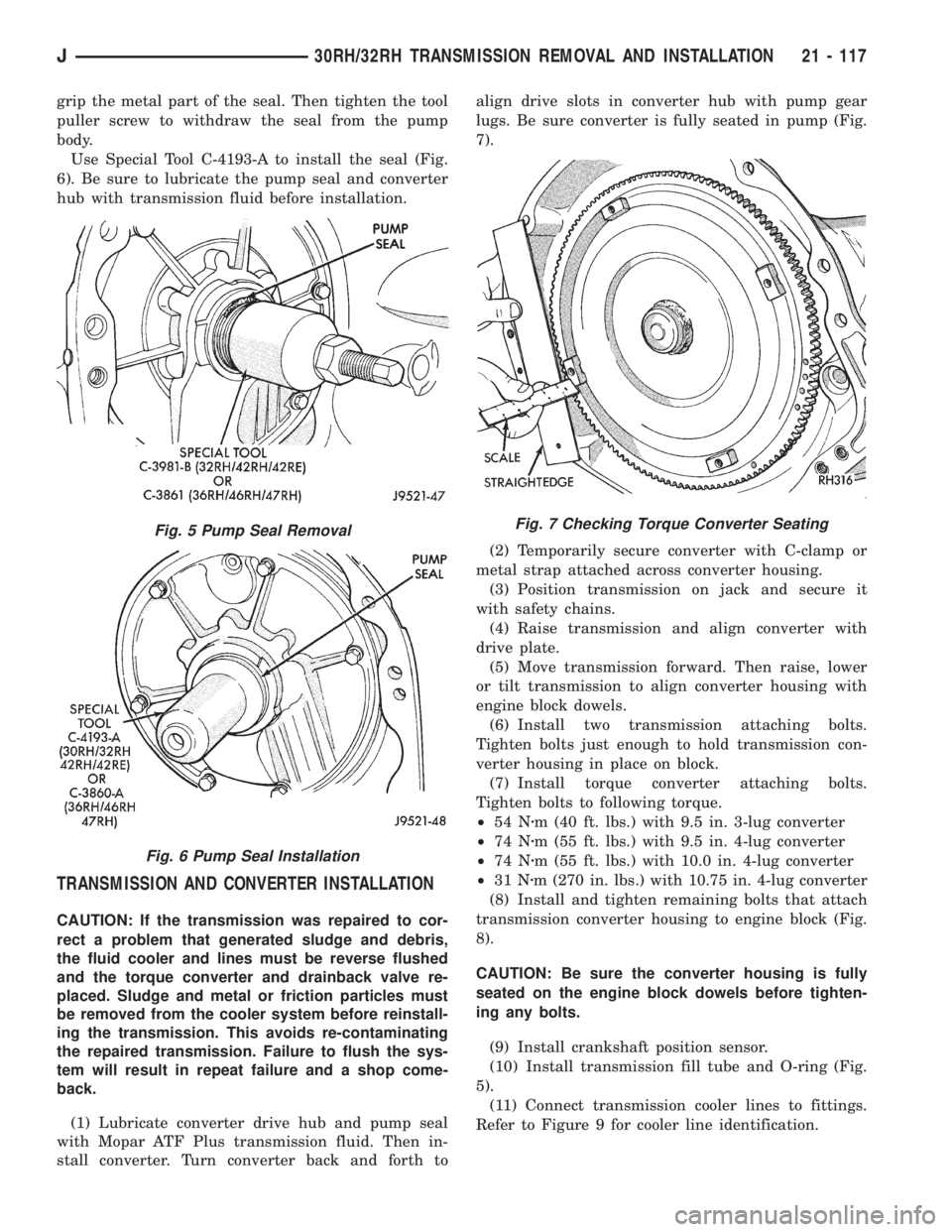
grip the metal part of the seal. Then tighten the tool
puller screw to withdraw the seal from the pump
body.
Use Special Tool C-4193-A to install the seal (Fig.
6). Be sure to lubricate the pump seal and converter
hub with transmission fluid before installation.
TRANSMISSION AND CONVERTER INSTALLATION
CAUTION: If the transmission was repaired to cor-
rect a problem that generated sludge and debris,
the fluid cooler and lines must be reverse flushed
and the torque converter and drainback valve re-
placed. Sludge and metal or friction particles must
be removed from the cooler system before reinstall-
ing the transmission. This avoids re-contaminating
the repaired transmission. Failure to flush the sys-
tem will result in repeat failure and a shop come-
back.
(1) Lubricate converter drive hub and pump seal
with Mopar ATF Plus transmission fluid. Then in-
stall converter. Turn converter back and forth toalign drive slots in converter hub with pump gear
lugs. Be sure converter is fully seated in pump (Fig.
7).
(2) Temporarily secure converter with C-clamp or
metal strap attached across converter housing.
(3) Position transmission on jack and secure it
with safety chains.
(4) Raise transmission and align converter with
drive plate.
(5) Move transmission forward. Then raise, lower
or tilt transmission to align converter housing with
engine block dowels.
(6) Install two transmission attaching bolts.
Tighten bolts just enough to hold transmission con-
verter housing in place on block.
(7) Install torque converter attaching bolts.
Tighten bolts to following torque.
²54 Nzm (40 ft. lbs.) with 9.5 in. 3-lug converter
²74 Nzm (55 ft. lbs.) with 9.5 in. 4-lug converter
²74 Nzm (55 ft. lbs.) with 10.0 in. 4-lug converter
²31 Nzm (270 in. lbs.) with 10.75 in. 4-lug converter
(8) Install and tighten remaining bolts that attach
transmission converter housing to engine block (Fig.
8).
CAUTION: Be sure the converter housing is fully
seated on the engine block dowels before tighten-
ing any bolts.
(9) Install crankshaft position sensor.
(10) Install transmission fill tube and O-ring (Fig.
5).
(11) Connect transmission cooler lines to fittings.
Refer to Figure 9 for cooler line identification.
Fig. 5 Pump Seal Removal
Fig. 6 Pump Seal Installation
Fig. 7 Checking Torque Converter Seating
J30RH/32RH TRANSMISSION REMOVAL AND INSTALLATION 21 - 117
Page 1680 of 2158
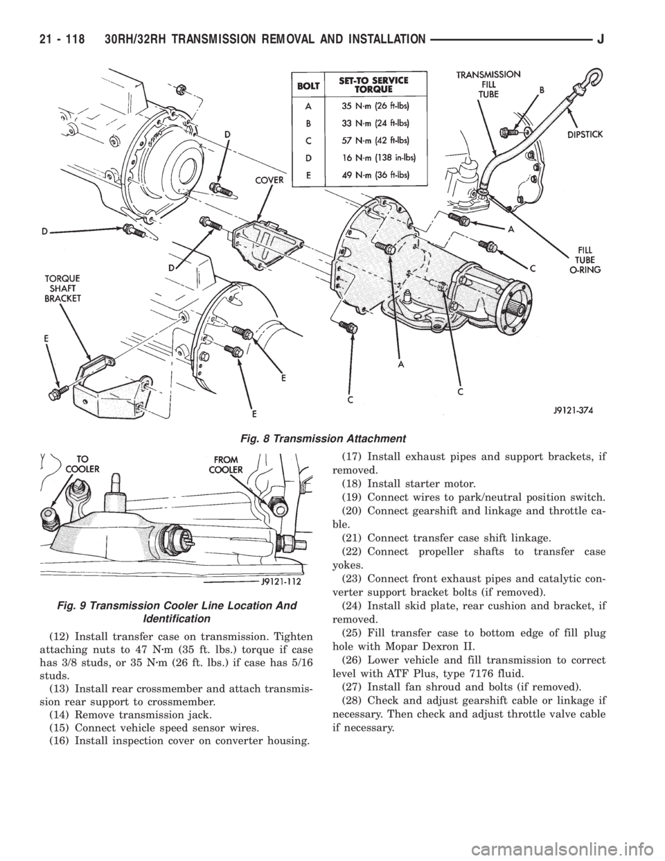
(12) Install transfer case on transmission. Tighten
attaching nuts to 47 Nzm (35 ft. lbs.) torque if case
has 3/8 studs, or 35 Nzm (26 ft. lbs.) if case has 5/16
studs.
(13) Install rear crossmember and attach transmis-
sion rear support to crossmember.
(14) Remove transmission jack.
(15) Connect vehicle speed sensor wires.
(16) Install inspection cover on converter housing.(17) Install exhaust pipes and support brackets, if
removed.
(18) Install starter motor.
(19) Connect wires to park/neutral position switch.
(20) Connect gearshift and linkage and throttle ca-
ble.
(21) Connect transfer case shift linkage.
(22) Connect propeller shafts to transfer case
yokes.
(23) Connect front exhaust pipes and catalytic con-
verter support bracket bolts (if removed).
(24) Install skid plate, rear cushion and bracket, if
removed.
(25) Fill transfer case to bottom edge of fill plug
hole with Mopar Dexron II.
(26) Lower vehicle and fill transmission to correct
level with ATF Plus, type 7176 fluid.
(27) Install fan shroud and bolts (if removed).
(28) Check and adjust gearshift cable or linkage if
necessary. Then check and adjust throttle valve cable
if necessary.
Fig. 8 Transmission Attachment
Fig. 9 Transmission Cooler Line Location And
Identification
21 - 118 30RH/32RH TRANSMISSION REMOVAL AND INSTALLATIONJ
Page 1692 of 2158
if damaged. Inspect the park gear for chipped or
worn gear teeth or damaged ring grooves. Replace
the gear, if damaged.
Check the teeth on the park gear for wear or dam-
age. Replace the gear if necessary. Inspect the metal
seal rings on the park gear hub. Replace the rings
only if severely worn, or broken.
Minor scratches, or burrs on governor components
can be cleaned up with oil-soaked crocus cloth. How-
ever, do not attempt to salvage components that are
severely worn or scored.
The governor valve is made of aluminum and
the output shaft has been spotfaced to accept
the valve. The aluminum valve must not be
used in prior transmissions. The valve can only
be used with an output shaft that has been
spotfaced for valve end clearance. In addition,
the governor body and output shaft must be
properly indexed during reassembly. Be sure to
index these components as described in the
Transmission Assembly and Adjustment proce-
dures.
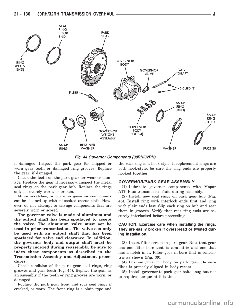
Check condition of the park gear seal rings, ring
grooves and gear teeth (Fig. 45). Replace the gear as
an assembly if the teeth or ring grooves are worn, or
damaged.
Replace the park gear front and rear seal rings if
cracked, or worn. The front ring is a plain type andthe rear ring is a hook style. If replacement rings are
both hook-style, be sure the ring ends are properly
hooked together.
GOVERNOR/PARK GEAR ASSEMBLY
(1) Lubricate governor components with Mopar
ATF Plus transmission fluid during assembly.
(2) Install new seal rings on park gear hub (Fig.
45). Install ring with interlock ends first and ring
with plain ends last. Slip each ring on hub and seat
them in grooves. Verify that rear ring ends are se-
curely interlocked before proceeding.
CAUTION: Exercise care when installing the rings.
They are easily broken if overspread or twisted dur-
ing installation.
(3) Insert filter screen in park gear. Note that gear
has one filter bore that is concentric and one that
has a notch in it. Filter goes in bore that is concen-
tric as shown (Fig. 39).
(4) Position governor body on park gear. Be sure
filter is properly aligned in body recess.
(5) Install governor-to-park gear bolts snug but not
to required torque at this time.
Fig. 44 Governor Components (30RH/32RH)
21 - 130 30RH/32RH TRANSMISSION OVERHAULJ
Page 1694 of 2158
oil pumps has a new design drive lug. The new
design incorporates tapered drive flats instead
of the square lug used previously. The torque
converter hub has also been redesigned to ac-
cept the new drive flats. If pump gear replace-
ment is necessary, be very sure to order and
install the correct style gears.
Inspect the pump and reaction shaft support bush-
ings. Minor bushing wear is acceptable. Replace the
bushings only if scored, or severely worn.
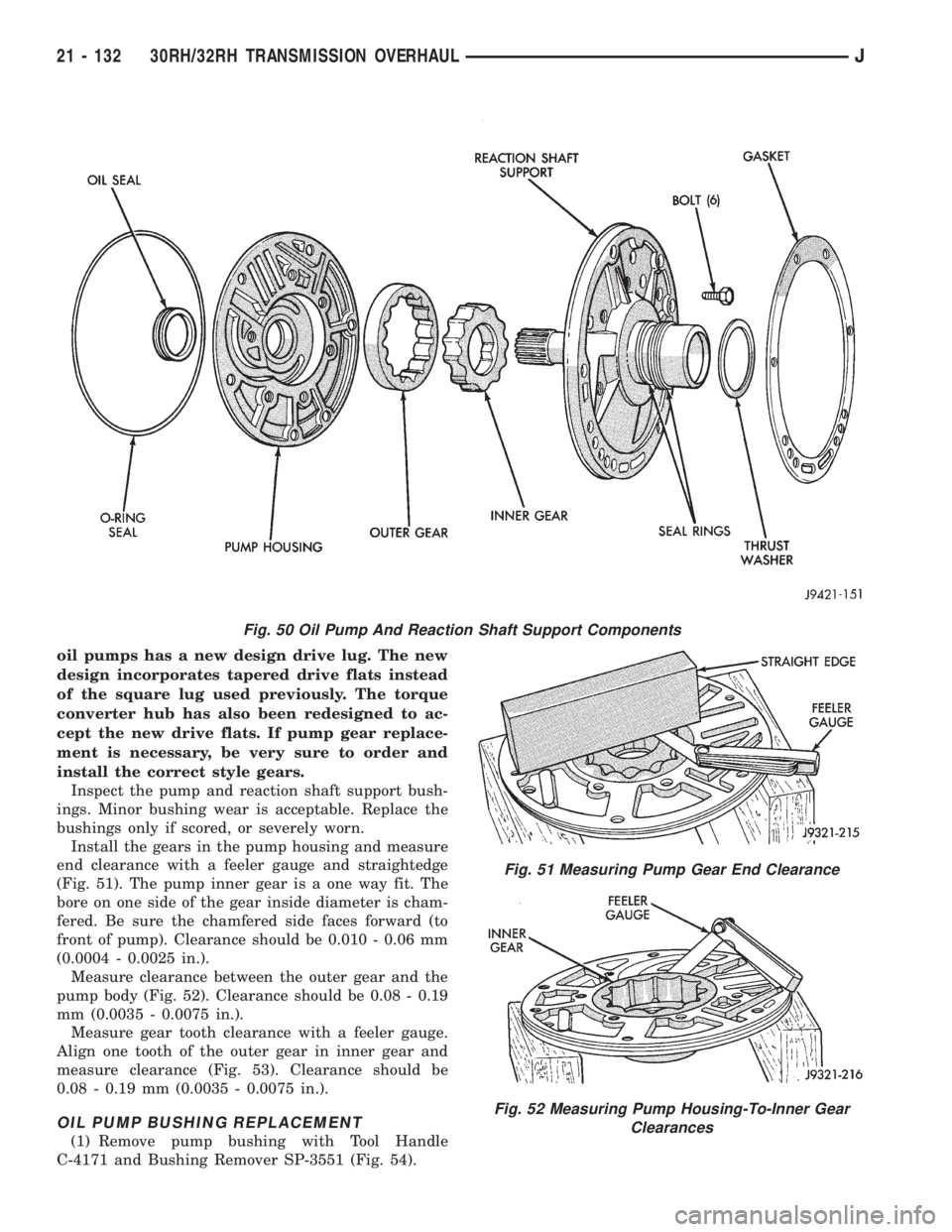
Install the gears in the pump housing and measure
end clearance with a feeler gauge and straightedge
(Fig. 51). The pump inner gear is a one way fit. The
bore on one side of the gear inside diameter is cham-
fered. Be sure the chamfered side faces forward (to
front of pump). Clearance should be 0.010 - 0.06 mm
(0.0004 - 0.0025 in.).
Measure clearance between the outer gear and the
pump body (Fig. 52). Clearance should be 0.08 - 0.19
mm (0.0035 - 0.0075 in.).
Measure gear tooth clearance with a feeler gauge.
Align one tooth of the outer gear in inner gear and
measure clearance (Fig. 53). Clearance should be
0.08 - 0.19 mm (0.0035 - 0.0075 in.).
OIL PUMP BUSHING REPLACEMENT
(1) Remove pump bushing with Tool Handle
C-4171 and Bushing Remover SP-3551 (Fig. 54).
Fig. 50 Oil Pump And Reaction Shaft Support Components
Fig. 51 Measuring Pump Gear End Clearance
Fig. 52 Measuring Pump Housing-To-Inner Gear
Clearances
21 - 132 30RH/32RH TRANSMISSION OVERHAULJ