1995 JEEP YJ ignition
[x] Cancel search: ignitionPage 1457 of 2158
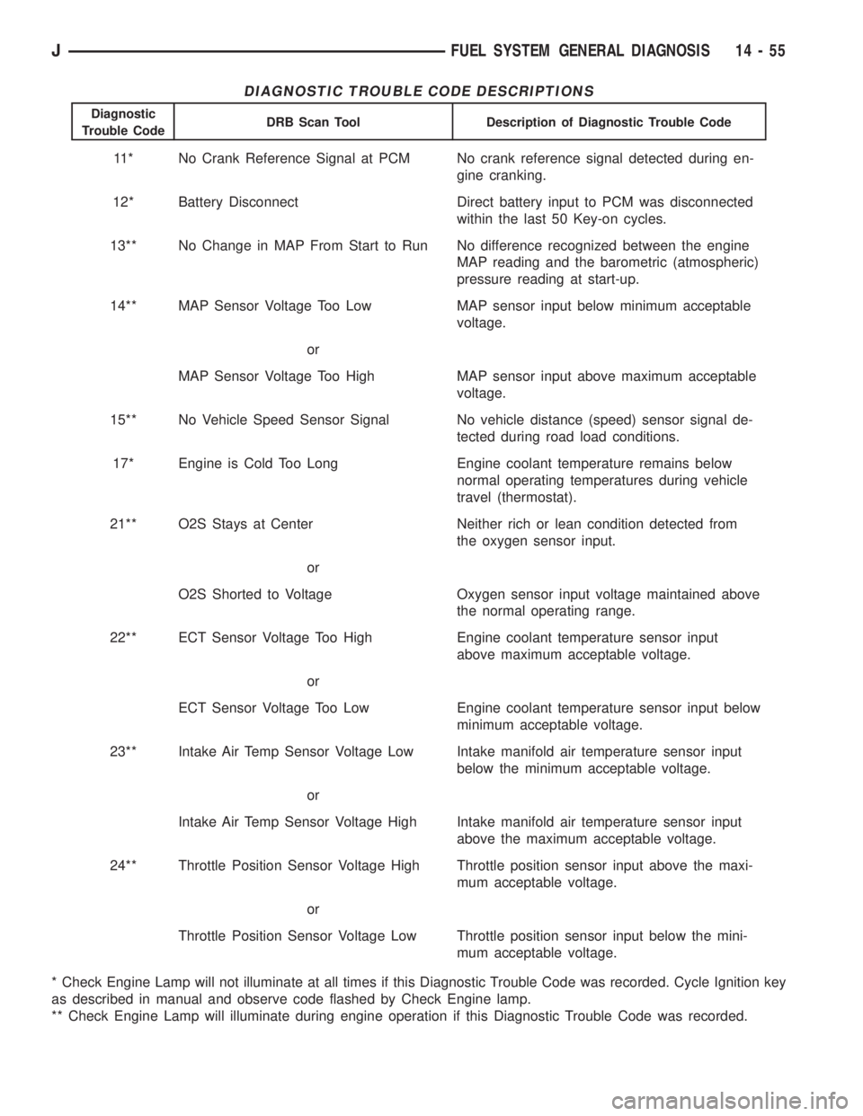
DIAGNOSTIC TROUBLE CODE DESCRIPTIONS
Diagnostic
Trouble CodeDRB Scan Tool Description of Diagnostic Trouble Code
11* No Crank Reference Signal at PCM No crank reference signal detected during en-
gine cranking.
12* Battery Disconnect Direct battery input to PCM was disconnected
within the last 50 Key-on cycles.
13** No Change in MAP From Start to Run No difference recognized between the engine
MAP reading and the barometric (atmospheric)
pressure reading at start-up.
14** MAP Sensor Voltage Too Low MAP sensor input below minimum acceptable
voltage.
or
MAP Sensor Voltage Too High MAP sensor input above maximum acceptable
voltage.
15** No Vehicle Speed Sensor Signal No vehicle distance (speed) sensor signal de-
tected during road load conditions.
17* Engine is Cold Too Long Engine coolant temperature remains below
normal operating temperatures during vehicle
travel (thermostat).
21** O2S Stays at Center Neither rich or lean condition detected from
the oxygen sensor input.
or
O2S Shorted to Voltage Oxygen sensor input voltage maintained above
the normal operating range.
22** ECT Sensor Voltage Too High Engine coolant temperature sensor input
above maximum acceptable voltage.
or
ECT Sensor Voltage Too Low Engine coolant temperature sensor input below
minimum acceptable voltage.
23** Intake Air Temp Sensor Voltage Low Intake manifold air temperature sensor input
below the minimum acceptable voltage.
or
Intake Air Temp Sensor Voltage High Intake manifold air temperature sensor input
above the maximum acceptable voltage.
24** Throttle Position Sensor Voltage High Throttle position sensor input above the maxi-
mum acceptable voltage.
or
Throttle Position Sensor Voltage Low Throttle position sensor input below the mini-
mum acceptable voltage.
* Check Engine Lamp will not illuminate at all times if this Diagnostic Trouble Code was recorded. Cycle Ignition key
as described in manual and observe code flashed by Check Engine lamp.
** Check Engine Lamp will illuminate during engine operation if this Diagnostic Trouble Code was recorded.
JFUEL SYSTEM GENERAL DIAGNOSIS 14 - 55
Page 1458 of 2158
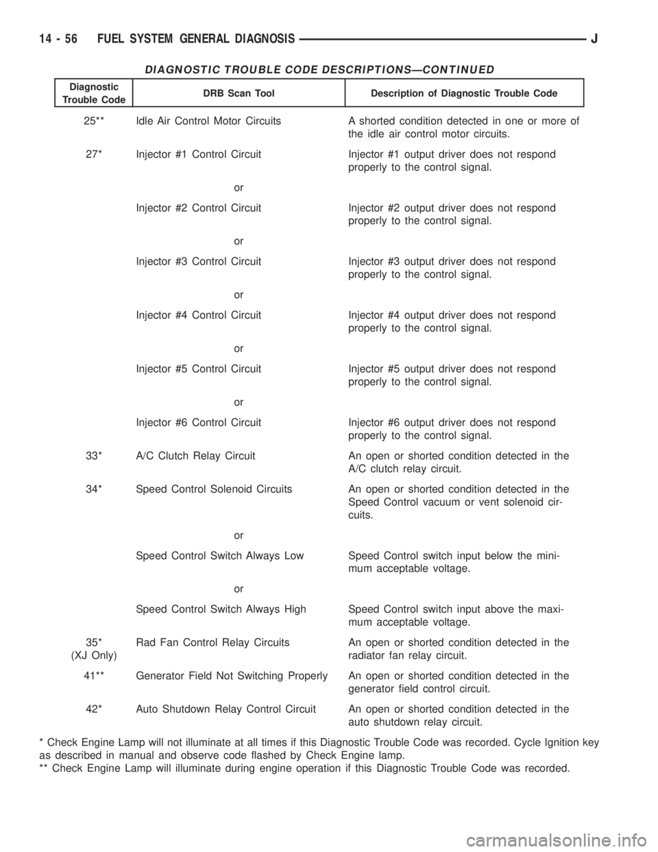
DIAGNOSTIC TROUBLE CODE DESCRIPTIONSÐCONTINUED
Diagnostic
Trouble CodeDRB Scan Tool Description of Diagnostic Trouble Code
25** Idle Air Control Motor Circuits A shorted condition detected in one or more of
the idle air control motor circuits.
27* Injector #1 Control Circuit Injector #1 output driver does not respond
properly to the control signal.
or
Injector #2 Control Circuit Injector #2 output driver does not respond
properly to the control signal.
or
Injector #3 Control Circuit Injector #3 output driver does not respond
properly to the control signal.
or
Injector #4 Control Circuit Injector #4 output driver does not respond
properly to the control signal.
or
Injector #5 Control Circuit Injector #5 output driver does not respond
properly to the control signal.
or
Injector #6 Control Circuit Injector #6 output driver does not respond
properly to the control signal.
33* A/C Clutch Relay Circuit An open or shorted condition detected in the
A/C clutch relay circuit.
34* Speed Control Solenoid Circuits An open or shorted condition detected in the
Speed Control vacuum or vent solenoid cir-
cuits.
or
Speed Control Switch Always Low Speed Control switch input below the mini-
mum acceptable voltage.
or
Speed Control Switch Always High Speed Control switch input above the maxi-
mum acceptable voltage.
35*
(XJ Only)Rad Fan Control Relay Circuits An open or shorted condition detected in the
radiator fan relay circuit.
41** Generator Field Not Switching Properly An open or shorted condition detected in the
generator field control circuit.
42* Auto Shutdown Relay Control Circuit An open or shorted condition detected in the
auto shutdown relay circuit.
* Check Engine Lamp will not illuminate at all times if this Diagnostic Trouble Code was recorded. Cycle Ignition key
as described in manual and observe code flashed by Check Engine lamp.
** Check Engine Lamp will illuminate during engine operation if this Diagnostic Trouble Code was recorded.
14 - 56 FUEL SYSTEM GENERAL DIAGNOSISJ
Page 1459 of 2158
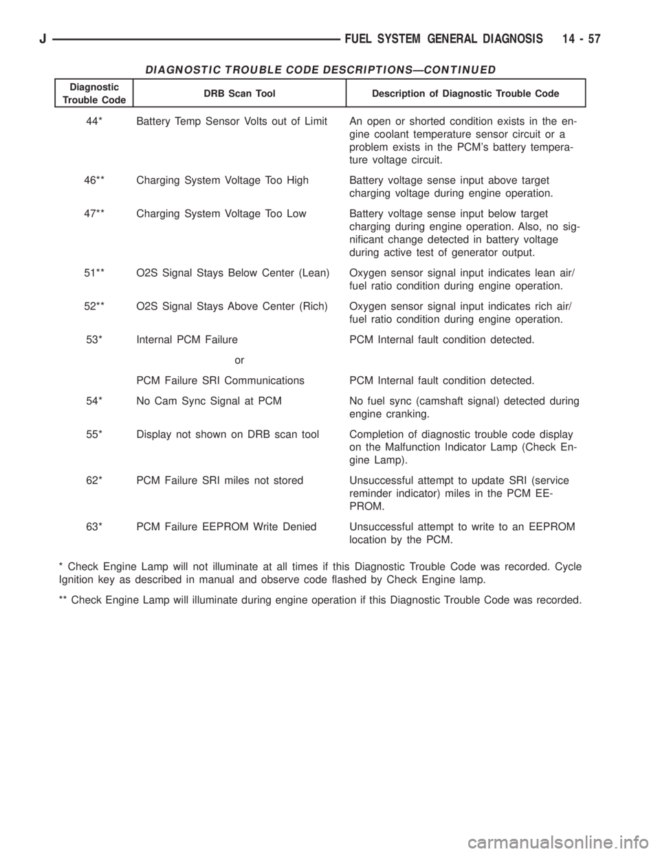
DIAGNOSTIC TROUBLE CODE DESCRIPTIONSÐCONTINUED
Diagnostic
Trouble CodeDRB Scan Tool Description of Diagnostic Trouble Code
44* Battery Temp Sensor Volts out of Limit An open or shorted condition exists in the en-
gine coolant temperature sensor circuit or a
problem exists in the PCM's battery tempera-
ture voltage circuit.
46** Charging System Voltage Too High Battery voltage sense input above target
charging voltage during engine operation.
47** Charging System Voltage Too Low Battery voltage sense input below target
charging during engine operation. Also, no sig-
nificant change detected in battery voltage
during active test of generator output.
51** O2S Signal Stays Below Center (Lean) Oxygen sensor signal input indicates lean air/
fuel ratio condition during engine operation.
52** O2S Signal Stays Above Center (Rich) Oxygen sensor signal input indicates rich air/
fuel ratio condition during engine operation.
53* Internal PCM Failure PCM Internal fault condition detected.
or
PCM Failure SRI Communications PCM Internal fault condition detected.
54* No Cam Sync Signal at PCM No fuel sync (camshaft signal) detected during
engine cranking.
55* Display not shown on DRB scan tool Completion of diagnostic trouble code display
on the Malfunction Indicator Lamp (Check En-
gine Lamp).
62* PCM Failure SRI miles not stored Unsuccessful attempt to update SRI (service
reminder indicator) miles in the PCM EE-
PROM.
63* PCM Failure EEPROM Write Denied Unsuccessful attempt to write to an EEPROM
location by the PCM.
* Check Engine Lamp will not illuminate at all times if this Diagnostic Trouble Code was recorded. Cycle
Ignition key as described in manual and observe code flashed by Check Engine lamp.
** Check Engine Lamp will illuminate during engine operation if this Diagnostic Trouble Code was recorded.
JFUEL SYSTEM GENERAL DIAGNOSIS 14 - 57
Page 1460 of 2158
MULTI-PORT FUEL INJECTION (MFI)ÐCOMPONENT REMOVAL/INSTALLATION
INDEX
page page
Accelerator Pedal and Throttle Cable........... 58
Air Cleaner Element....................... 59
Air Cleaner Housing....................... 58
Air Conditioning (A/C) Clutch Relay............ 58
Automatic Shutdown (ASD) Relay............. 59
Brake Switch............................ 59
Camshaft Position Sensor................... 60
Crankshaft Position Sensor.................. 60
Engine Coolant Temperature Sensor........... 60
Fuel Filter............................... 60
Fuel Injector............................. 60
Fuel Pressure Regulator.................... 61
Fuel Pump Module........................ 61
Fuel Pump Relay......................... 61
Fuel Rail Assembly........................ 62
Fuel System Pressure Release Procedure....... 62
Fuel Tank Pressure Relief/Rollover Valve........ 62Fuel Tanks.............................. 62
Fuel Tubes/Lines/Hoses and Clamps........... 62
Idle Air Control (IAC) Motor.................. 62
Ignition Coil............................. 62
Intake Manifold........................... 63
Intake Manifold Air Temperature Sensor......... 60
Manifold Absolute Pressure (Map) Sensor....... 63
Oxygen (O2S) Sensor...................... 63
Park Neutral Switch....................... 63
Power Steering Pressure SwitchÐ2.5L
Engine Only............................ 63
Powertrain Control Module (PCM)............. 64
Quick-Connect Fittings..................... 64
Throttle Body............................ 64
Throttle Position Sensor (TPS)............... 65
Torque Converter Clutch Relay............... 65
Vehicle Speed Sensor...................... 66
ACCELERATOR PEDAL AND THROTTLE CABLE
Refer to the Accelerator Pedal and Throttle Cable
section of this group for removal/installation proce-
dures.
AIR CONDITIONING (A/C) CLUTCH RELAY
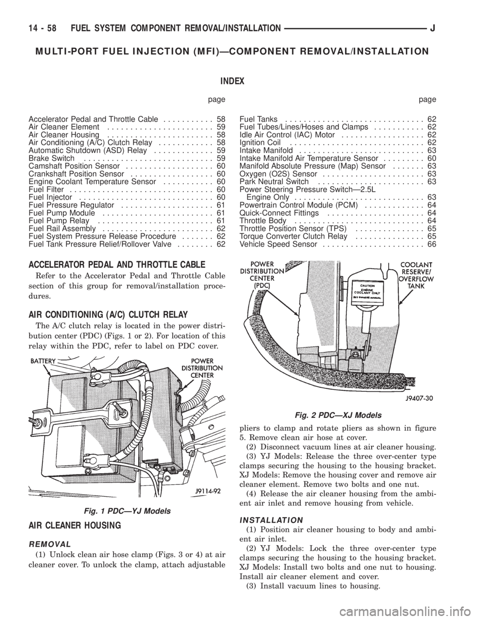
The A/C clutch relay is located in the power distri-
bution center (PDC) (Figs. 1 or 2). For location of this
relay within the PDC, refer to label on PDC cover.
AIR CLEANER HOUSING
REMOVAL
(1) Unlock clean air hose clamp (Figs. 3 or 4) at air
cleaner cover. To unlock the clamp, attach adjustablepliers to clamp and rotate pliers as shown in figure
5. Remove clean air hose at cover.
(2) Disconnect vacuum lines at air cleaner housing.
(3) YJ Models: Release the three over-center type
clamps securing the housing to the housing bracket.
XJ Models: Remove the housing cover and remove air
cleaner element. Remove two bolts and one nut.
(4) Release the air cleaner housing from the ambi-
ent air inlet and remove housing from vehicle.
INSTALLATION
(1) Position air cleaner housing to body and ambi-
ent air inlet.
(2) YJ Models: Lock the three over-center type
clamps securing the housing to the housing bracket.
XJ Models: Install two bolts and one nut to housing.
Install air cleaner element and cover.
(3) Install vacuum lines to housing.
Fig. 1 PDCÐYJ Models
Fig. 2 PDCÐXJ Models
14 - 58 FUEL SYSTEM COMPONENT REMOVAL/INSTALLATIONJ
Page 1462 of 2158
CAMSHAFT POSITION SENSOR
For removal/installation procedures, refer to Group
8D, Ignition System. See Camshaft Position Sensor.
INTAKE MANIFOLD AIR TEMPERATURE SENSOR
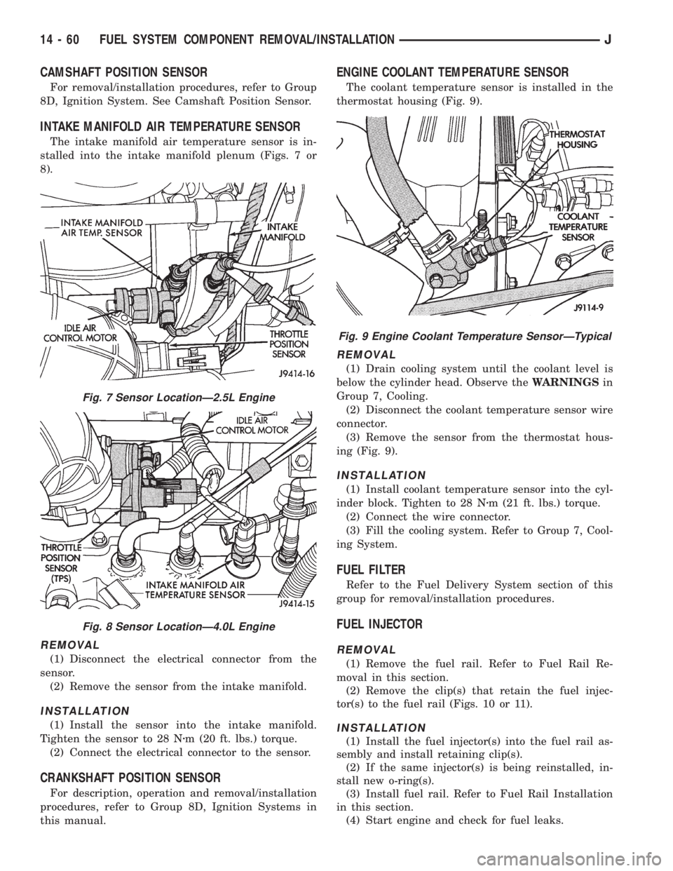
The intake manifold air temperature sensor is in-
stalled into the intake manifold plenum (Figs. 7 or
8).
REMOVAL
(1) Disconnect the electrical connector from the
sensor.
(2) Remove the sensor from the intake manifold.
INSTALLATION
(1) Install the sensor into the intake manifold.
Tighten the sensor to 28 Nzm (20 ft. lbs.) torque.
(2) Connect the electrical connector to the sensor.
CRANKSHAFT POSITION SENSOR
For description, operation and removal/installation
procedures, refer to Group 8D, Ignition Systems in
this manual.
ENGINE COOLANT TEMPERATURE SENSOR
The coolant temperature sensor is installed in the
thermostat housing (Fig. 9).
REMOVAL
(1) Drain cooling system until the coolant level is
below the cylinder head. Observe theWARNINGSin
Group 7, Cooling.
(2) Disconnect the coolant temperature sensor wire
connector.
(3) Remove the sensor from the thermostat hous-
ing (Fig. 9).
INSTALLATION
(1) Install coolant temperature sensor into the cyl-
inder block. Tighten to 28 Nzm (21 ft. lbs.) torque.
(2) Connect the wire connector.
(3) Fill the cooling system. Refer to Group 7, Cool-
ing System.
FUEL FILTER
Refer to the Fuel Delivery System section of this
group for removal/installation procedures.
FUEL INJECTOR
REMOVAL
(1) Remove the fuel rail. Refer to Fuel Rail Re-
moval in this section.
(2) Remove the clip(s) that retain the fuel injec-
tor(s) to the fuel rail (Figs. 10 or 11).
INSTALLATION
(1) Install the fuel injector(s) into the fuel rail as-
sembly and install retaining clip(s).
(2) If the same injector(s) is being reinstalled, in-
stall new o-ring(s).
(3) Install fuel rail. Refer to Fuel Rail Installation
in this section.
(4) Start engine and check for fuel leaks.
Fig. 7 Sensor LocationÐ2.5L Engine
Fig. 8 Sensor LocationÐ4.0L Engine
Fig. 9 Engine Coolant Temperature SensorÐTypical
14 - 60 FUEL SYSTEM COMPONENT REMOVAL/INSTALLATIONJ
Page 1464 of 2158
FUEL RAIL ASSEMBLY
REMOVAL
WARNING: THE FUEL SYSTEM IS UNDER CON-
STANT FUEL PRESSURE (EVEN WITH THE ENGINE
OFF) OF APPROXIMATELY 131-269 KPA (19-39 PSI).
THIS PRESSURE MUST BE RELEASED BEFORE
SERVICING THE FUEL RAIL.
(1) Remove fuel tank filler tube cap.
(2) Disconnect the negative battery cable from bat-
tery.
(3) Perform the Fuel System Pressure Release Pro-
cedure as described in the Fuel Delivery System sec-
tion of this Group.
(4) Remove and numerically attach a tag (if fuel
injector is not already tagged), the injector harness
connectors. Do this at each injector (Fig. 12).
(5) Disconnect vacuum line from fuel pressure reg-
ulator (Fig. 12).
(6) Disconnect fuel supply line from fuel rail and
the fuel return line from fuel pressure regulator (Fig.
12). Refer to Fuel Tubes/Lines/Hoses and Clamps, or
Quick-Connect Fittings. These can both be found in
the Fuel Delivery section of this group.
(7) Remove fuel rail mounting bolts.
On models with automatic transmissions, it may be
necessary to remove automatic transmission throttle
line pressure cable and bracket. This will aid in fuel
rail assembly removal.
(8) Remove fuel rail by gently rocking until all the
fuel injectors are out of the intake manifold.
INSTALLATION
(1) Position tips of all fuel injectors into the corre-
sponding injector bore in the intake manifold. Seat
injectors into manifold.
(2) Tighten fuel rail mounting bolts to 27 Nzm (20
ft. lbs.) torque.
(3) Connect injector harness connectors to appro-
priate (tagged) injector.
(4) Connect both fuel lines to fuel rail. Refer to the
Fuel Delivery section of this group for procedures.
(5) Connect vacuum supply line to fuel pressure
regulator.
(6) Install protective cap to pressure test port fit-
ting.
(7) Install fuel tank cap.
(8) Connect negative battery cable to battery.
(9) Start engine and check for fuel leaks.
FUEL SYSTEM PRESSURE RELEASE PROCEDURE
WARNING: THE FUEL SYSTEM IS UNDER A CON-
STANT PRESSURE (EVEN WITH THE ENGINE OFF)
OF APPROXIMATELY 100 KPA (14.5 PSI). BEFORE
SERVICING THE FUEL PUMP, FUEL RAIL, FUELLINES, FUEL FILTER OR FUEL INJECTOR, THE
FUEL SYSTEM PRESSURE MUST BE RELEASED.
Refer to the Fuel Delivery System section of this
group. See Fuel Pressure Release procedure.
FUEL TANKS
Refer to the Fuel Tank section of this group for re-
moval/installation procedures.
FUEL TANK PRESSURE RELIEF/ROLLOVER VALVE
Refer to the Fuel Tank section of this group for re-
moval/installation procedures.
FUEL TUBES/LINES/HOSES AND CLAMPS
Refer to the Fuel Delivery System section of this
group for removal/installation procedures. Also refer
to Quick-Connect Fittings in the Fuel Delivery sec-
tion of this group.
IDLE AIR CONTROL (IAC) MOTOR
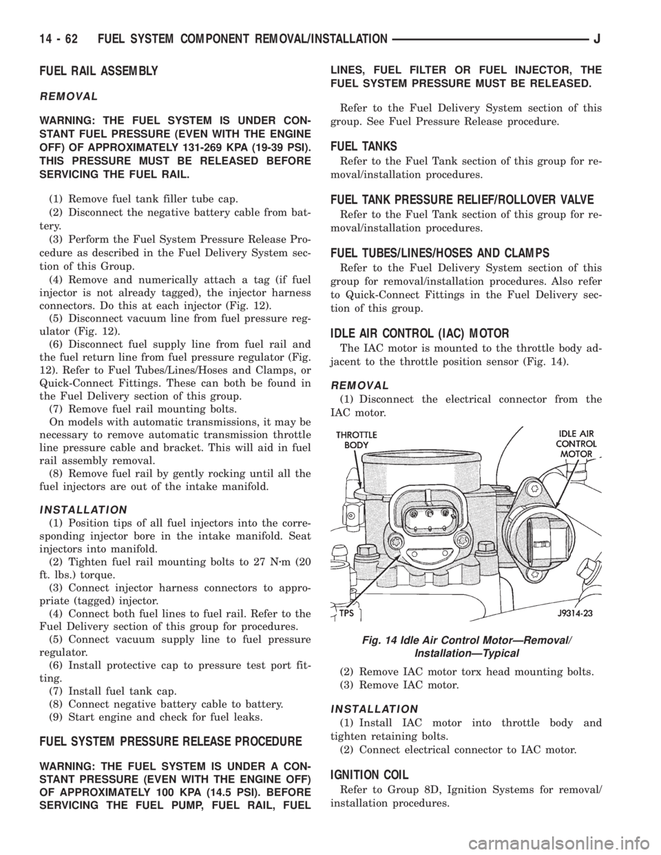
The IAC motor is mounted to the throttle body ad-
jacent to the throttle position sensor (Fig. 14).
REMOVAL
(1) Disconnect the electrical connector from the
IAC motor.
(2) Remove IAC motor torx head mounting bolts.
(3) Remove IAC motor.
INSTALLATION
(1) Install IAC motor into throttle body and
tighten retaining bolts.
(2) Connect electrical connector to IAC motor.
IGNITION COIL
Refer to Group 8D, Ignition Systems for removal/
installation procedures.
Fig. 14 Idle Air Control MotorÐRemoval/
InstallationÐTypical
14 - 62 FUEL SYSTEM COMPONENT REMOVAL/INSTALLATIONJ
Page 1486 of 2158
POWER STEERING PUMP
Hydraulic pressure is provided for operation of the
power steering gear by a belt driven power steering
pump. The power steering pump is a constant flow
rate and displacement, vane-type pump. The internal
parts in the housing operate submerged in fluid. The
flow control orifice is part of the high pressure line
fitting. The pressure relief valve inside the flow con-
trol valve limits the pump pressure.
Power steering pumps have different pres-
sure rates and are not interchangeable with
other pumps.
The power steering pump is connected to the steer-
ing gear via high pressure and return hose. The
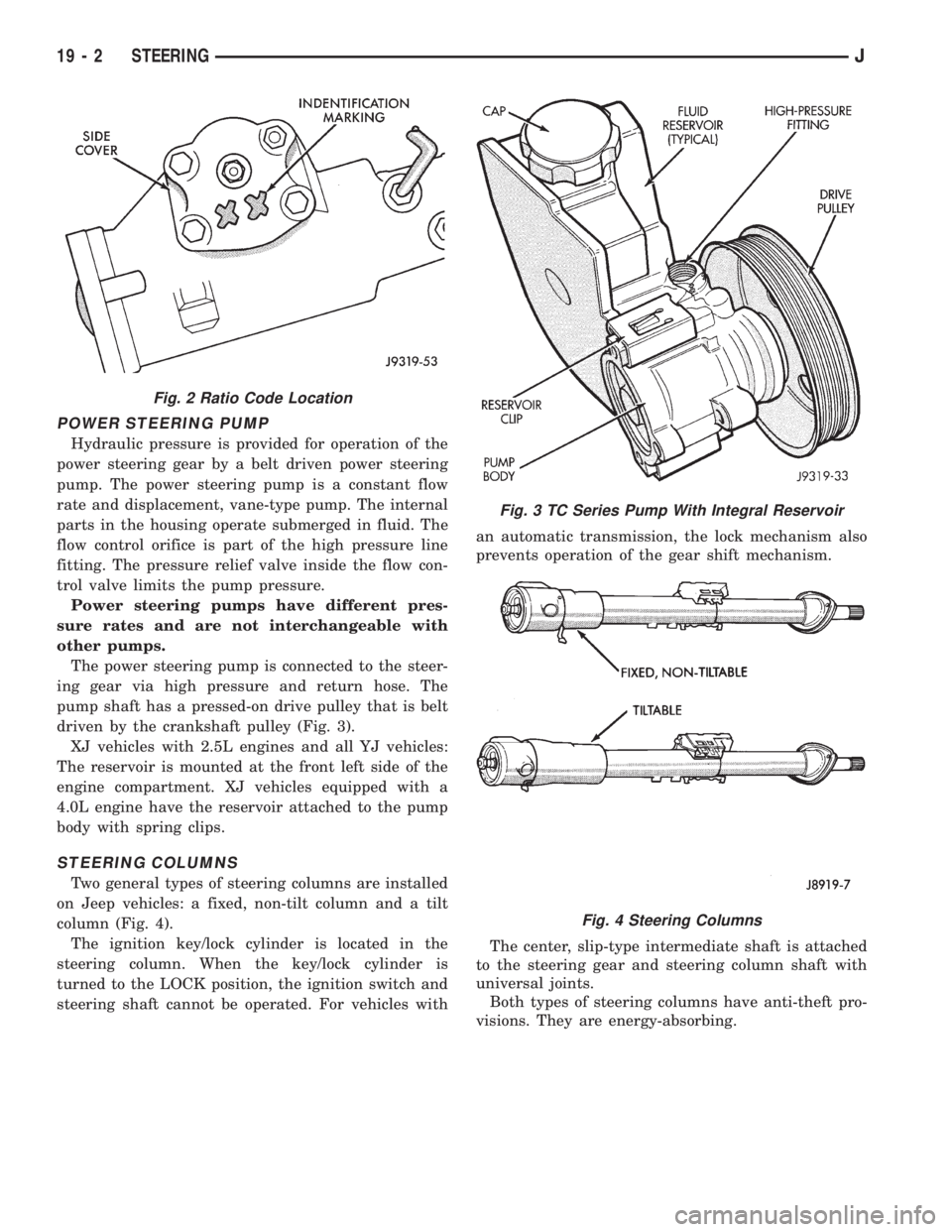
pump shaft has a pressed-on drive pulley that is belt
driven by the crankshaft pulley (Fig. 3).
XJ vehicles with 2.5L engines and all YJ vehicles:
The reservoir is mounted at the front left side of the
engine compartment. XJ vehicles equipped with a
4.0L engine have the reservoir attached to the pump
body with spring clips.
STEERING COLUMNS
Two general types of steering columns are installed
on Jeep vehicles: a fixed, non-tilt column and a tilt
column (Fig. 4).
The ignition key/lock cylinder is located in the
steering column. When the key/lock cylinder is
turned to the LOCK position, the ignition switch and
steering shaft cannot be operated. For vehicles withan automatic transmission, the lock mechanism also
prevents operation of the gear shift mechanism.
The center, slip-type intermediate shaft is attached
to the steering gear and steering column shaft with
universal joints.
Both types of steering columns have anti-theft pro-
visions. They are energy-absorbing.
Fig. 2 Ratio Code Location
Fig. 3 TC Series Pump With Integral Reservoir
Fig. 4 Steering Columns
19 - 2 STEERINGJ
Page 1536 of 2158
(4) From the end of travel, rotate the rotor 2 1/2
full turns in the COUNTER CLOCKWISE direction.
The horn wire should end up at the top and the
squib wire at the bottom (Fig. 9).
(5) Install the steering wheel and air bag module,
refer to Steering Wheel Installation.
COLUMN ASSEMBLY REPLACEMENT
CAUTION: Bumping, jolting and hammering on the
steering column shaft and gear shift tube must be
avoided during all service procedures.
REMOVAL
(1) Make sure the front wheels are in thestraight
aheadposition.
(2) Observe Cautions and disconnect the negative
(ground) cable from the battery.
(3) Disarm airbag, refer to Arming/Disarming Air-
bag in this section.
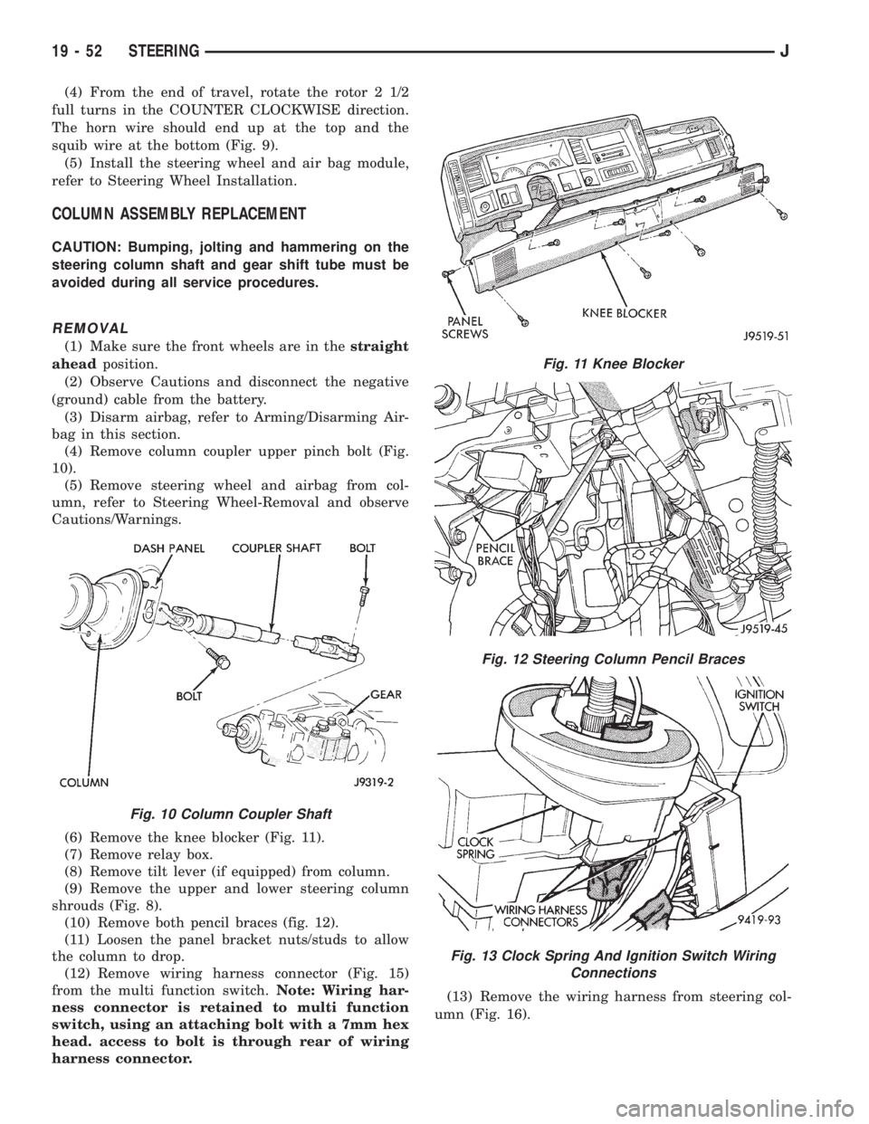
(4) Remove column coupler upper pinch bolt (Fig.
10).
(5) Remove steering wheel and airbag from col-
umn, refer to Steering Wheel-Removal and observe
Cautions/Warnings.
(6) Remove the knee blocker (Fig. 11).
(7) Remove relay box.
(8) Remove tilt lever (if equipped) from column.
(9) Remove the upper and lower steering column
shrouds (Fig. 8).
(10) Remove both pencil braces (fig. 12).
(11) Loosen the panel bracket nuts/studs to allow
the column to drop.
(12) Remove wiring harness connector (Fig. 15)
from the multi function switch.Note: Wiring har-
ness connector is retained to multi function
switch, using an attaching bolt with a 7mm hex
head. access to bolt is through rear of wiring
harness connector.(13) Remove the wiring harness from steering col-
umn (Fig. 16).
Fig. 10 Column Coupler Shaft
Fig. 11 Knee Blocker
Fig. 12 Steering Column Pencil Braces
Fig. 13 Clock Spring And Ignition Switch Wiring
Connections
19 - 52 STEERINGJ