1995 JEEP YJ tire type
[x] Cancel search: tire typePage 1316 of 2158
LUBRICATION SYSTEM
A gearÐtype positive displacement pump is
mounted at the underside of the block opposite the
No. 4 main bearing. The pump draws oil through the
screen and inlet tube from the sump at the rear of
the oil pan. The oil is driven between the drive and
idler gears and pump body, then forced through the
outlet to the block. An oil gallery in the block chan-
nels the oil to the inlet side of the full flow oil filter.
After passing through the filter element, the oil
passes from the center outlet of the filter through an
oil gallery that channels the oil up to the main gal-
lery which extends the entire length of the block.
Galleries extend downward from the main oil gal-
lery to the upper shell of each main bearing. The
crankshaft is drilled internally to pass oil from the
main bearing journals (except number 4 main bear-
ing journal) to the connecting rod journals. Each con-
necting rod bearing cap has a small squirt hole, oilpasses through the squirt hole and is thrown off as
the rod rotates. This oil throwoff lubricates the cam-
shaft lobes, distributor drive gear, cylinder walls, and
piston pins.
The hydraulic valve tappets receive oil directly
from the main oil gallery. Oil is provided to the cam-
shaft bearing through galleries. The front camshaft
bearing journal passes oil through the camshaft
sprocket to the timing chain. Oil drains back to the
oil pan under the number one main bearing cap.
The oil supply for the rocker arms and bridged
pivot assemblies is provided by the hydraulic valve
tappets which pass oil through hollow push rods to a
hole in the corresponding rocker arm. Oil from the
rocker arm lubricates the valve train components,
then passes down through the push rod guide holes
in the cylinder head past the valve tappet area, and
returns to the oil pan.
J2.5L ENGINE 9 - 37
Page 1358 of 2158
LUBRICATION SYSTEM
A gearÐtype positive displacement pump is
mounted at the underside of the block opposite the
No. 4 main bearing. The pump draws oil through the
screen and inlet tube from the sump at the rear of
the oil pan. The oil is driven between the drive and
idler gears and pump body, then forced through the
outlet to the block. An oil gallery in the block chan-
nels the oil to the inlet side of the full flow oil filter.
After passing through the filter element, the oil
passes from the center outlet of the filter through an
oil gallery that channels the oil up to the main gal-
lery which extends the entire length of the block.
Galleries extend downward from the main oil gal-
lery to the upper shell of each main bearing. The
crankshaft is drilled internally to pass oil from the
main bearing journals (except number 4 main bear-
ing journal) to the connecting rod journals. Each con-
necting rod bearing cap has a small squirt hole, oilpasses through the squirt hole and is thrown off as
the rod rotates. This oil throwoff lubricates the cam-
shaft lobes, distributor drive gear, cylinder walls, and
piston pins.
The hydraulic valve tappets receive oil directly
from the main oil gallery. Oil is provided to the cam-
shaft bearing through galleries. The front camshaft
bearing journal passes oil through the camshaft
sprocket to the timing chain. Oil drains back to the
oil pan under the number one main bearing cap.
The oil supply for the rocker arms and bridged
pivot assemblies is provided by the hydraulic valve
tappets which pass oil through hollow push rods to a
hole in the corresponding rocker arm. Oil from the
rocker arm lubricates the valve train components,
then passes down through the push rod guide holes
in the cylinder head past the valve tappet area, and
returns to the oil pan.
J4.0L ENGINE 9 - 79
Page 1671 of 2158
Inspection
Check the sprag shaft for scores and for free move-
ment in the housing and sprag.
Check the sprag and control rod springs for loss of
tension or distortion. Check the square lug on the
sprag for broken edges. Check the lugs on the gover-
nor support (park gear) for broken edges. Replace
any park lock components that are worn or damaged.
Check the knob on the end of the control rod for
nicks, burrs and free turning. Replace the rod if the
knob is grooved, or worn, or if the rod is bent. The
park lock rods used in Chrysler 3-speed transmis-
sions are different lengths. If the rod must be re-
placed, be sure to install the correct length and
shape rod.
COMPONENT INSTALLATION
(1) Install park lock rod on valve body.
(2) Install reaction plug and pin assembly in the
housing and install the snap ring.
(3) Position sprag and spring in housing and in-
stall sprag shaft. Be sure square lug on sprag is fac-
ing park gear and that spring is positioned so it
moves sprag away from park gear.
(4) Install valve body.
(5) Install adapter housing and transfer case.
PARK/NEUTRAL POSITION SWITCH SERVICE
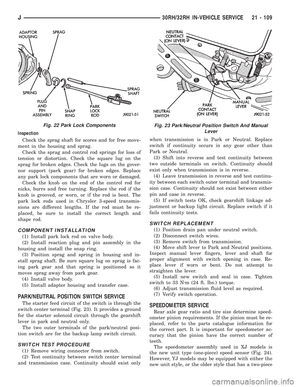
The starter feed circuit of the switch is through the
switch center terminal (Fig. 23). It provides a ground
for the starter solenoid circuit through the gearshift
lever in park and neutral only.
The two outer terminals of the park/neutral posi-
tion switch are for the backup lamp switch circuit.
SWITCH TEST PROCEDURE
(1) Remove wiring connector from switch.
(2) Test continuity between switch center terminal
and transmission case. Continuity should exist onlywhen transmission is in Park or Neutral. Replace
switch if continuity occurs in any gear other than
Park or Neutral.
(3) Shift into reverse and test continuity between
two outside terminals on switch. Continuity should
exist only when transmission is in reverse.
(4) Leave transmission in reverse and test continu-
ity between each switch outer terminal and transmis-
sion case. Continuity should not exist between either
pin and case in reverse.
(5) If switch tests OK, check gearshift linkage ad-
justment or backup light circuit. Replace switch if it
fails continuity tests.
SWITCH REPLACEMENT
(1) Position drain pan under neutral switch.
(2) Disconnect switch wires.
(3) Remove switch from transmission.
(4) Move shift lever to Park and Neutral positions.
Inspect manual lever fingers, lever and shaft for
proper alignment with switch opening in case. Re-
place lever if worn or bent. Do not attempt to
straighten the lever.
(5) Install new switch and seal in case. Tighten
switch to 33 Nzm (24 ft. lbs.) torque.
(6) Adjust transmission fluid level as required.
(7) Verify switch operation.
SPEEDOMETER SERVICE
Rear axle gear ratio and tire size determine speed-
ometer pinion requirements. If the pinion must be re-
placed, refer to the parts catalogue information for
the correct part. It is important for speedometer ac-
curacy that the pinion have the correct number of
teeth.
The speedometer assembly used in XJ models is
the new unit type (one-piece) speed sensor (Fig. 24).
However, YJ models may be equipped with either the
new unit style, or the older style that has a two-piece
Fig. 22 Park Lock ComponentsFig. 23 Park/Neutral Position Switch And Manual
Lever
J30RH/32RH IN-VEHICLE SERVICE 21 - 109
Page 1674 of 2158
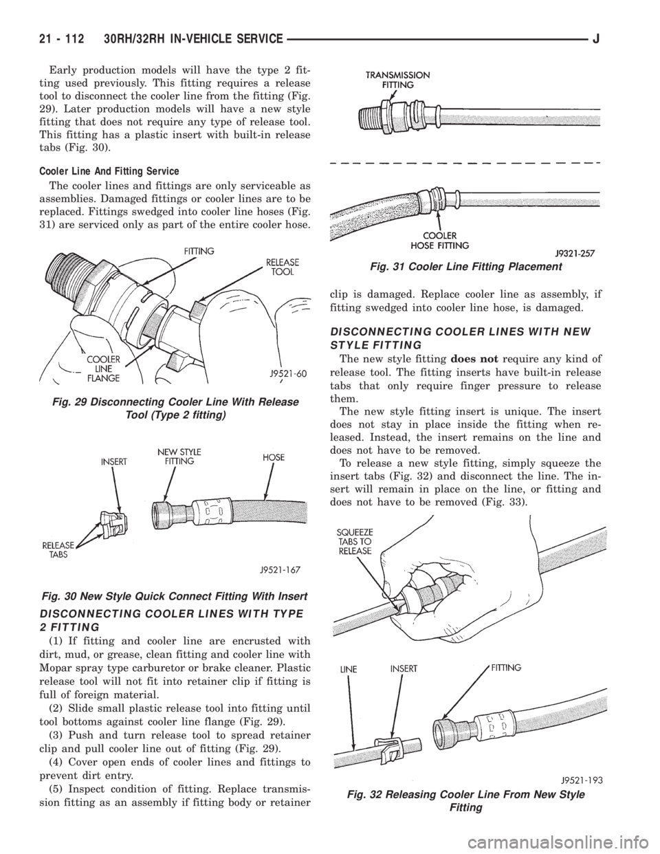
Early production models will have the type 2 fit-
ting used previously. This fitting requires a release
tool to disconnect the cooler line from the fitting (Fig.
29). Later production models will have a new style
fitting that does not require any type of release tool.
This fitting has a plastic insert with built-in release
tabs (Fig. 30).
Cooler Line And Fitting Service
The cooler lines and fittings are only serviceable as
assemblies. Damaged fittings or cooler lines are to be
replaced. Fittings swedged into cooler line hoses (Fig.
31) are serviced only as part of the entire cooler hose.
DISCONNECTING COOLER LINES WITH TYPE
2 FITTING
(1) If fitting and cooler line are encrusted with
dirt, mud, or grease, clean fitting and cooler line with
Mopar spray type carburetor or brake cleaner. Plastic
release tool will not fit into retainer clip if fitting is
full of foreign material.
(2) Slide small plastic release tool into fitting until
tool bottoms against cooler line flange (Fig. 29).
(3) Push and turn release tool to spread retainer
clip and pull cooler line out of fitting (Fig. 29).
(4) Cover open ends of cooler lines and fittings to
prevent dirt entry.
(5) Inspect condition of fitting. Replace transmis-
sion fitting as an assembly if fitting body or retainerclip is damaged. Replace cooler line as assembly, if
fitting swedged into cooler line hose, is damaged.
DISCONNECTING COOLER LINES WITH NEW
STYLE FITTING
The new style fittingdoes notrequire any kind of
release tool. The fitting inserts have built-in release
tabs that only require finger pressure to release
them.
The new style fitting insert is unique. The insert
does not stay in place inside the fitting when re-
leased. Instead, the insert remains on the line and
does not have to be removed.
To release a new style fitting, simply squeeze the
insert tabs (Fig. 32) and disconnect the line. The in-
sert will remain in place on the line, or fitting and
does not have to be removed (Fig. 33).
Fig. 30 New Style Quick Connect Fitting With Insert
Fig. 29 Disconnecting Cooler Line With Release
Tool (Type 2 fitting)
Fig. 31 Cooler Line Fitting Placement
Fig. 32 Releasing Cooler Line From New Style
Fitting
21 - 112 30RH/32RH IN-VEHICLE SERVICEJ
Page 1907 of 2158
WHEELS AND TIRES
CONTENTS
page page
SPECIFICATIONS........................ 12
TIRES.................................. 1VEHICLE VIBRATION..................... 10
WHEELS................................ 6
TIRES
INDEX
page page
Cleaning of Tires.......................... 2
General Information........................ 1
Pressure Gauges.......................... 2
Repairing Leaks........................... 3
Replacement Tires......................... 2Rotation................................. 3
Tire Inflation Pressures...................... 2
Tire Noise or Vibration...................... 4
Tire Wear Patterns......................... 4
Tread Wear Indicators....................... 3
GENERAL INFORMATION
Tires are designed for each specific vehicle. They
provide the best overall performance for normal oper-
ation. The ride and handling characteristics match
the vehicle's requirements. With proper care they
will give excellent reliability, traction, skid resis-
tance, and tread life. These tires have specific load
carrying capacities. When correctly inflated, they will
operate properly.
Tires used in cool climates, and with light loads
will have a longer life than tires used in hot climates
with heavy loads. Abrasive road surfaces will acceler-
ate tire wear.
Driving habits have more effect on tire life than
any other factor. Careful drivers will obtain much
greater mileage than careless drivers.
Driving habits that shorten the life of any tire;
²Rapid acceleration and deceleration
²Severe application of brakes
²High-speed driving
²Taking turns at excessive speeds
²Striking curbs and other obstacles
It is very important to follow the tire rotation in-
terval
IDENTIFICATION
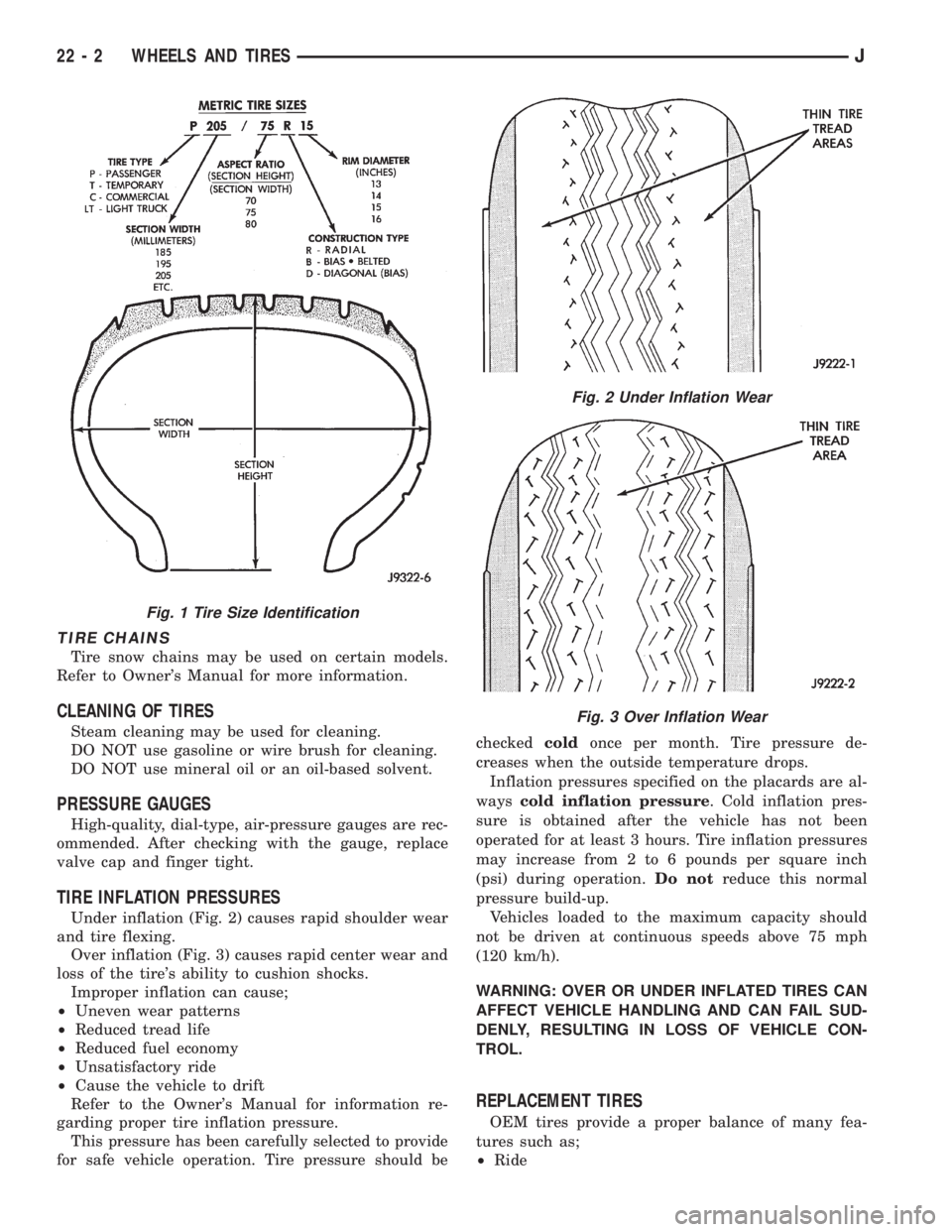
Tire type, size, aspect ratio and speed rating are
encoded in the letters and numbers imprinted on the
side wall of the tire. Refer to the chart to decipher
the tire identification code (Fig. 1).Performance tires will have a speed rating letter
after the aspect ratio number. The speed rating is not
always printed on the tire sidewall. The letterSin-
dicates that the tire is speed rated up to 112 mph.
²Qup to 100 mph
²Tup to 118 mph
²Uup to 124 mph
²Hup to 130 mph
²Vup to 149 mph
²Zmore than 149 mph (consult the tire manufac-
turer for the specific speed rating)
An All Season type tire will have eitherM+S,M
&SorMÐS(indicating mud and snow traction) im-
printed on the side wall.
RADIAL-PLY TIRES
Radial-ply tires improve handling, tread life, ride
quality and decrease rolling resistance.
Radial-ply tires must always be used in sets of
four. Under no circumstances should they be used on
the front only. They may be mixed with temporary
spare tires when necessary, but reduced speeds are
recommended.
Radial-ply tires have the same load-carrying capac-
ity as other types of tires of the same size. They use
the same recommended inflation pressures.
SPARE TIRE (TEMPORARY)
The compact spare tire is designed for emergency
use only. The original tire should be repaired and re-
installed at the first opportunity. Refer to Owner's
Manual for complete details.
JWHEELS AND TIRES 22 - 1
Page 1908 of 2158
TIRE CHAINS
Tire snow chains may be used on certain models.
Refer to Owner's Manual for more information.
CLEANING OF TIRES
Steam cleaning may be used for cleaning.
DO NOT use gasoline or wire brush for cleaning.
DO NOT use mineral oil or an oil-based solvent.
PRESSURE GAUGES
High-quality, dial-type, air-pressure gauges are rec-
ommended. After checking with the gauge, replace
valve cap and finger tight.
TIRE INFLATION PRESSURES
Under inflation (Fig. 2) causes rapid shoulder wear
and tire flexing.
Over inflation (Fig. 3) causes rapid center wear and
loss of the tire's ability to cushion shocks.
Improper inflation can cause;
²Uneven wear patterns
²Reduced tread life
²Reduced fuel economy
²Unsatisfactory ride
²Cause the vehicle to drift
Refer to the Owner's Manual for information re-
garding proper tire inflation pressure.
This pressure has been carefully selected to provide
for safe vehicle operation. Tire pressure should becheckedcoldonce per month. Tire pressure de-
creases when the outside temperature drops.
Inflation pressures specified on the placards are al-
wayscold inflation pressure. Cold inflation pres-
sure is obtained after the vehicle has not been
operated for at least 3 hours. Tire inflation pressures
may increase from 2 to 6 pounds per square inch
(psi) during operation.Do notreduce this normal
pressure build-up.
Vehicles loaded to the maximum capacity should
not be driven at continuous speeds above 75 mph
(120 km/h).
WARNING: OVER OR UNDER INFLATED TIRES CAN
AFFECT VEHICLE HANDLING AND CAN FAIL SUD-
DENLY, RESULTING IN LOSS OF VEHICLE CON-
TROL.
REPLACEMENT TIRES
OEM tires provide a proper balance of many fea-
tures such as;
²Ride
Fig. 1 Tire Size Identification
Fig. 2 Under Inflation Wear
Fig. 3 Over Inflation Wear
22 - 2 WHEELS AND TIRESJ
Page 1916 of 2158
VEHICLE VIBRATION
Vehicle vibration can be caused by:
²Tire/wheel unbalance or excessive runout
²Defective tires with extreme tread wear
²Nylon overlay flat spots (performance tires only)
²Incorrect wheel bearing adjustment (if applicable)
²Loose or worn suspension/steering components
²Certain tire tread patterns
²Incorrect drive shaft angles or excessive drive
shaft/yoke runout
²Defective or worn U-joints
²Excessive brake rotor or drum runout
²Loose engine or transmission supports/mounts
²And by engine operated accessories
Refer to the appropriate Groups in this man-
ual for additional information.
VIBRATION TYPES
There are two types of vehicle vibration:
²Mechanical
²Audible.
Mechanical vehicle vibration can be felt through
the seats, floor pan and/or steering wheel.
Audible vehicle vibration is heard above normal
background noise. The sound can be a droning or
drumming noise.
Vibrations are sensitive to change in engine torque,
vehicle speed or engine speed.
ENGINE TORQUE SENSITIVE VIBRATION
This vibration can be increased or decreased by:
²Accelerating
²Decelerating
²Coasting
²Maintaining a constant vehicle speed
VEHICLE SPEED SENSITIVE VIBRATION
This vibration condition always occurs at the same
vehicle speed regardless of the engine torque or en-
gine speed.
ENGINE SPEED (RPM) SENSITIVE VIBRATION
This vibration occurs at varying engine speeds. It
can be isolated by increasing or decreasing the en-
gine speed with the transmission in NEUTRAL posi-
tion.
VIBRATION DIAGNOSIS
A vibration diagnosis should always begin with a
10 mile (16 km) trip (to warm the vehicle and tires).
Then a road test to identify the vibration. Corrective
action should not be attempted until the vibration
type has been identified via a road test.
During the road test, drive the vehicle on a smooth
surface. If vibration exists, note and record the fol-
lowing information:²Identify the vehicle speed range when the vibra-
tion occurs
²Identify the type of vibration
²Identify the vibration sensitivity
²Determine if the vibration is affected by changes
in vehicle speed, engine speed and engine torque.
When the vibration has been identified, refer to the
Vibration Diagnosis chart for causes. Consider cor-
recting only those causes coded in the chart that are
related to the vibration condition.
Refer to the following cause codes and descriptions
for explanations when referring to the chart.
TRRÐTire and Wheel Radial Runout:Vehicle
speed sensitive, mechanical vibration. The runout
will not cause vibration below 20 mph (32 km/h).
WHÐWheel Hop:Vehicle speed sensitive, me-
chanical vibration. The wheel hop generates rapid
up-down movement in the steering wheel. The vibra-
tion is most noticeable in the 20 - 40 mph (32 - 64
km/h) range. The wheel hop will not cause vibration
below 20 mph (32 km/h). Wheel hop is caused by a
tire/wheel that has a radial runout of more than
0.045 of-an-inch (1.14 mm). If wheel runout is accept-
able and combined runout cannot be reduced by re-
positioning the tire on wheel, replace tire.
TBÐTire/Wheel Balance:Vehicle speed sensitive,
mechanical vibration. Static tire/wheel unbalance
will not cause vibration below 30 mph (46 km/h). Dy-
namic tire/wheel unbalance will not cause vibration
below 40 mph (64 km/h).
TLRÐTire/Wheel Lateral runout:Vehicle speed
sensitive, mechanical vibration. The runout will not
cause vibration below 50 - 55 mph (80 - 88 km/h). Ex-
cessive lateral runout will also cause front-end
shimmy.
TWÐTire Wear:Vehicle speed sensitive, audible
vibration. Abnormal tire wear causes small vibration
in the 30 - 55 mph (88 km/h) range. This will pro-
duce a whine noise at high speed. The whine will
change to a growl noise when the speed is reduced.
WÐTire Waddle:Vehicle speed sensitive, mechan-
ical vibration. Irregular tire uniformity can cause
side-to-side motion during speeds up to 15 mph (24
km/h). If the motion is excessive, identify the defec-
tive tire and replace it.
UAJÐUniversal Joint (Drive Shaft) Angles:
Torque/vehicle speed sensitive, mechanical/audible vi-
bration. Incorrect drive shaft angles cause mechani-
cal vibration below 20 mph (32 km/h) and in the 70
mph (112 km/h) range. The incorrect angles can also
produce an audible vibration in the 20 - 50 mph (32 -
80 km/h) range. Caster adjustment could be required
to correct the angles.
UJÐUniversal Joints:Engine torque/vehicle
speed sensitive, mechanical/audible vibration. If the
22 - 10 WHEELS AND TIRESJ
Page 1995 of 2158
TRAILER HITCH
TRAILER HITCHÐXJ
CLASS III HITCH
A class III weight-distributing/equalizer type hitch
can be used to tow a trailer:
²Having a maximum gross weight of 5,000 lbs/2250
kg.
²Having a maximum tongue weight of 750 lbs/332
kg).
The following vehicle basic equipment is required
for class III trailer towing:
²P205/75R15 or larger tires.
²Full size spare tire.
²Trailer sway control.
²Trailer tow wire harness and connector.
²Heavy duty turn signal flasher element.
²Heavy duty axle (with synthetic lubricant).
²Heavy duty cooling system.
²Heavy duty generator/battery.
²Auxiliary automatic transmission fluid cooler.
²I-6, 4.0L engine.
Wide-angle type door mirrors are recommended but
not required.
WIRE HARNESS CONNECTORS
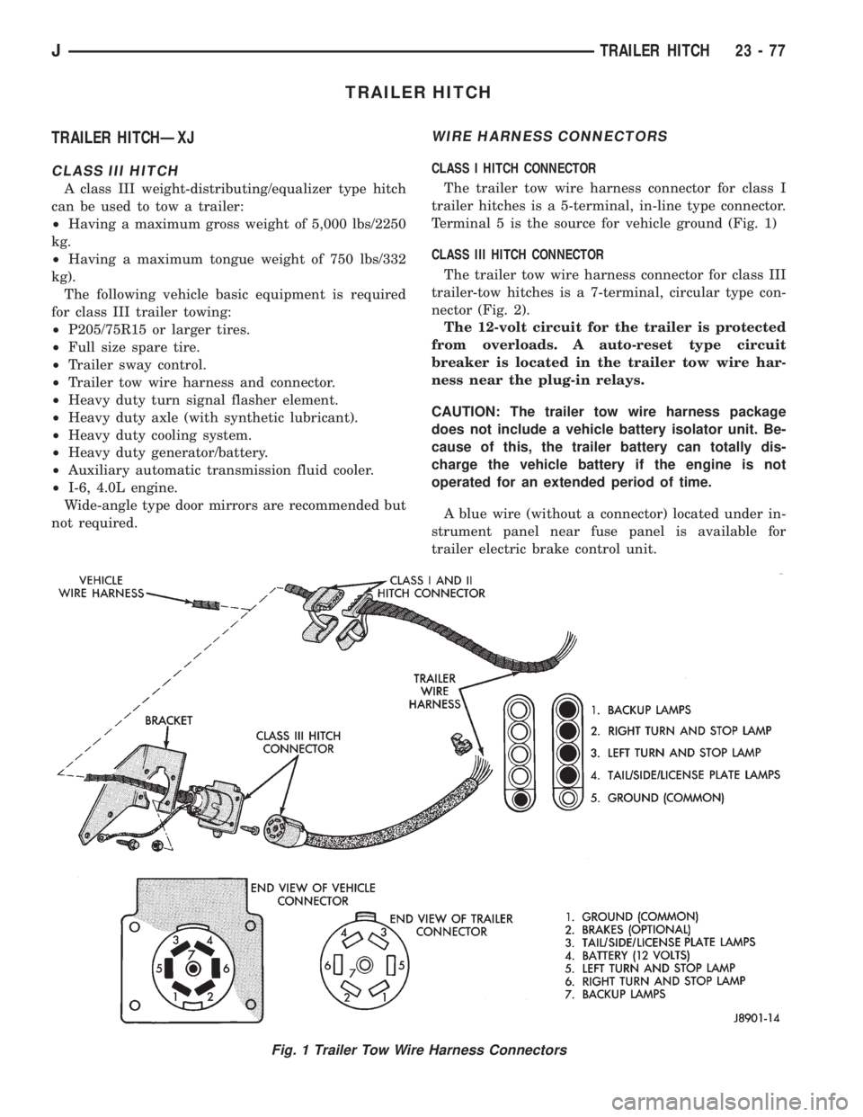
CLASS I HITCH CONNECTOR
The trailer tow wire harness connector for class I
trailer hitches is a 5-terminal, in-line type connector.
Terminal 5 is the source for vehicle ground (Fig. 1)
CLASS III HITCH CONNECTOR
The trailer tow wire harness connector for class III
trailer-tow hitches is a 7-terminal, circular type con-
nector (Fig. 2).
The 12-volt circuit for the trailer is protected
from overloads. A auto-reset type circuit
breaker is located in the trailer tow wire har-
ness near the plug-in relays.
CAUTION: The trailer tow wire harness package
does not include a vehicle battery isolator unit. Be-
cause of this, the trailer battery can totally dis-
charge the vehicle battery if the engine is not
operated for an extended period of time.
A blue wire (without a connector) located under in-
strument panel near fuse panel is available for
trailer electric brake control unit.
Fig. 1 Trailer Tow Wire Harness Connectors
JTRAILER HITCH 23 - 77