1995 JEEP YJ seats
[x] Cancel search: seatsPage 1675 of 2158
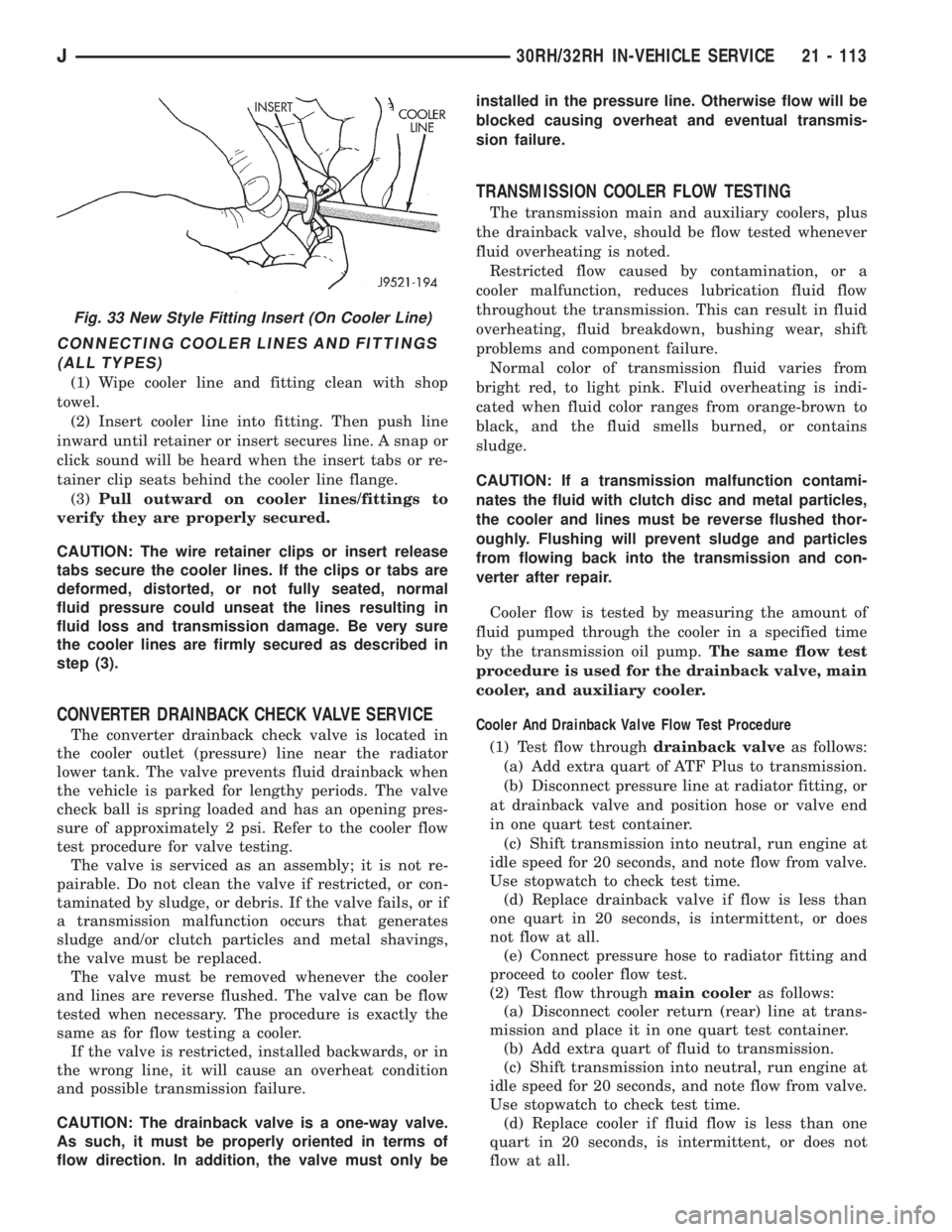
CONNECTING COOLER LINES AND FITTINGS
(ALL TYPES)
(1) Wipe cooler line and fitting clean with shop
towel.
(2) Insert cooler line into fitting. Then push line
inward until retainer or insert secures line. A snap or
click sound will be heard when the insert tabs or re-
tainer clip seats behind the cooler line flange.
(3)Pull outward on cooler lines/fittings to
verify they are properly secured.
CAUTION: The wire retainer clips or insert release
tabs secure the cooler lines. If the clips or tabs are
deformed, distorted, or not fully seated, normal
fluid pressure could unseat the lines resulting in
fluid loss and transmission damage. Be very sure
the cooler lines are firmly secured as described in
step (3).
CONVERTER DRAINBACK CHECK VALVE SERVICE
The converter drainback check valve is located in
the cooler outlet (pressure) line near the radiator
lower tank. The valve prevents fluid drainback when
the vehicle is parked for lengthy periods. The valve
check ball is spring loaded and has an opening pres-
sure of approximately 2 psi. Refer to the cooler flow
test procedure for valve testing.
The valve is serviced as an assembly; it is not re-
pairable. Do not clean the valve if restricted, or con-
taminated by sludge, or debris. If the valve fails, or if
a transmission malfunction occurs that generates
sludge and/or clutch particles and metal shavings,
the valve must be replaced.
The valve must be removed whenever the cooler
and lines are reverse flushed. The valve can be flow
tested when necessary. The procedure is exactly the
same as for flow testing a cooler.
If the valve is restricted, installed backwards, or in
the wrong line, it will cause an overheat condition
and possible transmission failure.
CAUTION: The drainback valve is a one-way valve.
As such, it must be properly oriented in terms of
flow direction. In addition, the valve must only beinstalled in the pressure line. Otherwise flow will be
blocked causing overheat and eventual transmis-
sion failure.
TRANSMISSION COOLER FLOW TESTING
The transmission main and auxiliary coolers, plus
the drainback valve, should be flow tested whenever
fluid overheating is noted.
Restricted flow caused by contamination, or a
cooler malfunction, reduces lubrication fluid flow
throughout the transmission. This can result in fluid
overheating, fluid breakdown, bushing wear, shift
problems and component failure.
Normal color of transmission fluid varies from
bright red, to light pink. Fluid overheating is indi-
cated when fluid color ranges from orange-brown to
black, and the fluid smells burned, or contains
sludge.
CAUTION: If a transmission malfunction contami-
nates the fluid with clutch disc and metal particles,
the cooler and lines must be reverse flushed thor-
oughly. Flushing will prevent sludge and particles
from flowing back into the transmission and con-
verter after repair.
Cooler flow is tested by measuring the amount of
fluid pumped through the cooler in a specified time
by the transmission oil pump.The same flow test
procedure is used for the drainback valve, main
cooler, and auxiliary cooler.
Cooler And Drainback Valve Flow Test Procedure
(1) Test flow throughdrainback valveas follows:
(a) Add extra quart of ATF Plus to transmission.
(b) Disconnect pressure line at radiator fitting, or
at drainback valve and position hose or valve end
in one quart test container.
(c) Shift transmission into neutral, run engine at
idle speed for 20 seconds, and note flow from valve.
Use stopwatch to check test time.
(d) Replace drainback valve if flow is less than
one quart in 20 seconds, is intermittent, or does
not flow at all.
(e) Connect pressure hose to radiator fitting and
proceed to cooler flow test.
(2) Test flow throughmain cooleras follows:
(a) Disconnect cooler return (rear) line at trans-
mission and place it in one quart test container.
(b) Add extra quart of fluid to transmission.
(c) Shift transmission into neutral, run engine at
idle speed for 20 seconds, and note flow from valve.
Use stopwatch to check test time.
(d) Replace cooler if fluid flow is less than one
quart in 20 seconds, is intermittent, or does not
flow at all.
Fig. 33 New Style Fitting Insert (On Cooler Line)
J30RH/32RH IN-VEHICLE SERVICE 21 - 113
Page 1715 of 2158
VALVE BODY ASSEMBLY AND ADJUSTMENT
CAUTION: Do not force valves or plugs into place
during reassembly. If the valve body bores, valves
and plugs are free of distortion or burrs, the valve
body components should all slide into place easily.
In addition, do not overtighten the transfer plate
and valve body screws during reassembly. Over-
tightening can distort the valve body resulting in
valve sticking, cross leakage and unsatisfactory op-
eration. Tighten valve body screws to recom-
mended torque only.
(1) Lubricate valve body bores, valves and plugs
with Mopar ATF Plus transmission fluid.
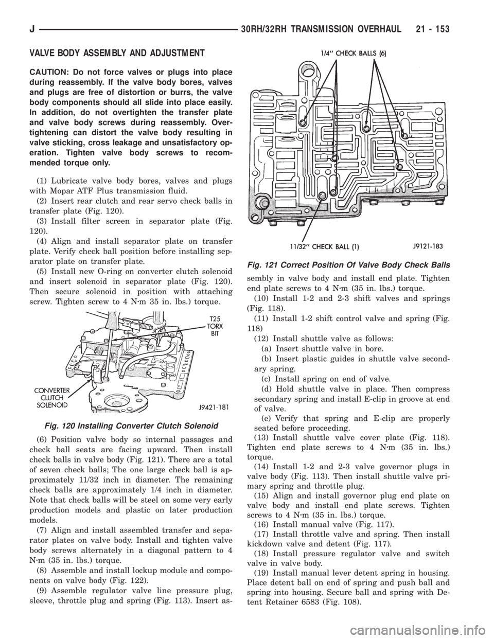
(2) Insert rear clutch and rear servo check balls in
transfer plate (Fig. 120).
(3) Install filter screen in separator plate (Fig.
120).
(4) Align and install separator plate on transfer
plate. Verify check ball position before installing sep-
arator plate on transfer plate.
(5) Install new O-ring on converter clutch solenoid
and insert solenoid in separator plate (Fig. 120).
Then secure solenoid in position with attaching
screw. Tighten screw to 4 Nzm 35 in. lbs.) torque.
(6) Position valve body so internal passages and
check ball seats are facing upward. Then install
check balls in valve body (Fig. 121). There are a total
of seven check balls; The one large check ball is ap-
proximately 11/32 inch in diameter. The remaining
check balls are approximately 1/4 inch in diameter.
Note that check balls will be steel on some very early
production models and plastic on later production
models.
(7) Align and install assembled transfer and sepa-
rator plates on valve body. Install and tighten valve
body screws alternately in a diagonal pattern to 4
Nzm (35 in. lbs.) torque.
(8) Assemble and install lockup module and compo-
nents on valve body (Fig. 122).
(9) Assemble regulator valve line pressure plug,
sleeve, throttle plug and spring (Fig. 113). Insert as-sembly in valve body and install end plate. Tighten
end plate screws to 4 Nzm (35 in. lbs.) torque.
(10) Install 1-2 and 2-3 shift valves and springs
(Fig. 118).
(11) Install 1-2 shift control valve and spring (Fig.
118)
(12) Install shuttle valve as follows:
(a) Insert shuttle valve in bore.
(b) Insert plastic guides in shuttle valve second-
ary spring.
(c) Install spring on end of valve.
(d) Hold shuttle valve in place. Then compress
secondary spring and install E-clip in groove at end
of valve.
(e) Verify that spring and E-clip are properly
seated before proceeding.
(13) Install shuttle valve cover plate (Fig. 118).
Tighten end plate screws to 4 Nzm (35 in. lbs.)
torque.
(14) Install 1-2 and 2-3 valve governor plugs in
valve body (Fig. 113). Then install shuttle valve pri-
mary spring and throttle plug.
(15) Align and install governor plug end plate on
valve body and install end plate screws. Tighten
screws to 4 Nzm (35 in. lbs.) torque.
(16) Install manual valve (Fig. 117).
(17) Install throttle valve and spring. Then install
kickdown valve and detent (Fig. 117).
(18) Install pressure regulator valve and switch
valve in valve body.
(19) Install manual lever detent spring in housing.
Place detent ball on end of spring and push ball and
spring into housing. Secure ball and spring with De-
tent Retainer 6583 (Fig. 108).
Fig. 120 Installing Converter Clutch Solenoid
Fig. 121 Correct Position Of Valve Body Check Balls
J30RH/32RH TRANSMISSION OVERHAUL 21 - 153
Page 1798 of 2158
(6) Lubricate and install new O-rings on clutch pis-
ton and install piston in drum.
(7) Install piston return springs.
(8) Compress piston return springs with Tool 7538
and shop press and install piston snap ring. Be sure
snap ring end gap is not aligned with any notches in
drum.
(9) Install cushion plate in drum. Concave side of
plate faces downward (Fig. 5).
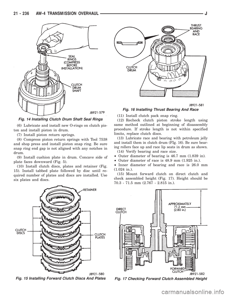
(10) Install clutch discs, plates and retainer (Fig.
15). Install tabbed plate followed by disc until re-
quired number of plates and discs are installed. Use
six plates and discs.(11) Install clutch pack snap ring.
(12) Recheck clutch piston stroke length using
same method outlined at beginning of disassembly
procedure. If stroke length is not within specified
limits, replace clutch discs.
(13) Lubricate race and bearing with petroleum jelly
and install them in clutch drum (FIg. 16). Be sure bear-
ing rollers face up and race lip seats in drum as shown.
(14) Verify bearing and race size.
²Outer diameter of bearing is 46.7 mm (1.839 in).
²Outer diameter of race is 48.9 mm (1.925 in.).
²Inner diameter of bearing and race is 26.0 mm
(1.024 in.).
(15) Mount forward clutch on direct clutch and
check assembled height (Fig. 17). Height should be
70.3 - 71.5 mm (2.767 - 2.815 in.).
Fig. 15 Installing Forward Clutch Discs And Plates
Fig. 16 Installing Thrust Bearing And Race
Fig. 17 Checking Forward Clutch Assembled Height
Fig. 14 Installing Clutch Drum Shaft Seal Rings
21 - 236 AW-4 TRANSMISSION OVERHAULJ
Page 1858 of 2158
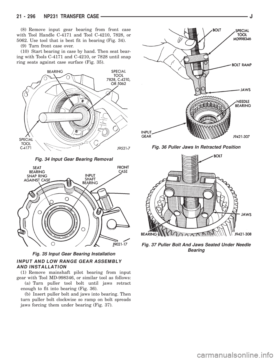
(8) Remove input gear bearing from front case
with Tool Handle C-4171 and Tool C-4210, 7828, or
5062. Use tool that is best fit in bearing (Fig. 34).
(9) Turn front case over.
(10) Start bearing in case by hand. Then seat bear-
ing with Tools C-4171 and C-4210, or 7828 until snap
ring seats against case surface (Fig. 35).
INPUT AND LOW RANGE GEAR ASSEMBLY
AND INSTALLATION
(1) Remove mainshaft pilot bearing from input
gear with Tool MD-998346, or similar tool as follows:
(a) Turn puller tool bolt until jaws retract
enough to fit into bearing (Fig. 36).
(b) Insert puller bolt and jaws into bearing. Then
turn puller bolt clockwise so ramp on bolt spreads
jaws forcing them under bearing (Fig. 37).
Fig. 34 Input Gear Bearing Removal
Fig. 35 Input Gear Bearing Installation
Fig. 36 Puller Jaws In Retracted Position
Fig. 37 Puller Bolt And Jaws Seated Under Needle
Bearing
21 - 296 NP231 TRANSFER CASEJ
Page 1916 of 2158
VEHICLE VIBRATION
Vehicle vibration can be caused by:
²Tire/wheel unbalance or excessive runout
²Defective tires with extreme tread wear
²Nylon overlay flat spots (performance tires only)
²Incorrect wheel bearing adjustment (if applicable)
²Loose or worn suspension/steering components
²Certain tire tread patterns
²Incorrect drive shaft angles or excessive drive
shaft/yoke runout
²Defective or worn U-joints
²Excessive brake rotor or drum runout
²Loose engine or transmission supports/mounts
²And by engine operated accessories
Refer to the appropriate Groups in this man-
ual for additional information.
VIBRATION TYPES
There are two types of vehicle vibration:
²Mechanical
²Audible.
Mechanical vehicle vibration can be felt through
the seats, floor pan and/or steering wheel.
Audible vehicle vibration is heard above normal
background noise. The sound can be a droning or
drumming noise.
Vibrations are sensitive to change in engine torque,
vehicle speed or engine speed.
ENGINE TORQUE SENSITIVE VIBRATION
This vibration can be increased or decreased by:
²Accelerating
²Decelerating
²Coasting
²Maintaining a constant vehicle speed
VEHICLE SPEED SENSITIVE VIBRATION
This vibration condition always occurs at the same
vehicle speed regardless of the engine torque or en-
gine speed.
ENGINE SPEED (RPM) SENSITIVE VIBRATION
This vibration occurs at varying engine speeds. It
can be isolated by increasing or decreasing the en-
gine speed with the transmission in NEUTRAL posi-
tion.
VIBRATION DIAGNOSIS
A vibration diagnosis should always begin with a
10 mile (16 km) trip (to warm the vehicle and tires).
Then a road test to identify the vibration. Corrective
action should not be attempted until the vibration
type has been identified via a road test.
During the road test, drive the vehicle on a smooth
surface. If vibration exists, note and record the fol-
lowing information:²Identify the vehicle speed range when the vibra-
tion occurs
²Identify the type of vibration
²Identify the vibration sensitivity
²Determine if the vibration is affected by changes
in vehicle speed, engine speed and engine torque.
When the vibration has been identified, refer to the
Vibration Diagnosis chart for causes. Consider cor-
recting only those causes coded in the chart that are
related to the vibration condition.
Refer to the following cause codes and descriptions
for explanations when referring to the chart.
TRRÐTire and Wheel Radial Runout:Vehicle
speed sensitive, mechanical vibration. The runout
will not cause vibration below 20 mph (32 km/h).
WHÐWheel Hop:Vehicle speed sensitive, me-
chanical vibration. The wheel hop generates rapid
up-down movement in the steering wheel. The vibra-
tion is most noticeable in the 20 - 40 mph (32 - 64
km/h) range. The wheel hop will not cause vibration
below 20 mph (32 km/h). Wheel hop is caused by a
tire/wheel that has a radial runout of more than
0.045 of-an-inch (1.14 mm). If wheel runout is accept-
able and combined runout cannot be reduced by re-
positioning the tire on wheel, replace tire.
TBÐTire/Wheel Balance:Vehicle speed sensitive,
mechanical vibration. Static tire/wheel unbalance
will not cause vibration below 30 mph (46 km/h). Dy-
namic tire/wheel unbalance will not cause vibration
below 40 mph (64 km/h).
TLRÐTire/Wheel Lateral runout:Vehicle speed
sensitive, mechanical vibration. The runout will not
cause vibration below 50 - 55 mph (80 - 88 km/h). Ex-
cessive lateral runout will also cause front-end
shimmy.
TWÐTire Wear:Vehicle speed sensitive, audible
vibration. Abnormal tire wear causes small vibration
in the 30 - 55 mph (88 km/h) range. This will pro-
duce a whine noise at high speed. The whine will
change to a growl noise when the speed is reduced.
WÐTire Waddle:Vehicle speed sensitive, mechan-
ical vibration. Irregular tire uniformity can cause
side-to-side motion during speeds up to 15 mph (24
km/h). If the motion is excessive, identify the defec-
tive tire and replace it.
UAJÐUniversal Joint (Drive Shaft) Angles:
Torque/vehicle speed sensitive, mechanical/audible vi-
bration. Incorrect drive shaft angles cause mechani-
cal vibration below 20 mph (32 km/h) and in the 70
mph (112 km/h) range. The incorrect angles can also
produce an audible vibration in the 20 - 50 mph (32 -
80 km/h) range. Caster adjustment could be required
to correct the angles.
UJÐUniversal Joints:Engine torque/vehicle
speed sensitive, mechanical/audible vibration. If the
22 - 10 WHEELS AND TIRESJ
Page 1998 of 2158
INTERIOR COMPONENTS
INDEX
page page
Assist HandleÐXJ........................ 89
B/C-Pillar and Liftgate Pillar Trim CoversÐXJ.... 88
Bucket Seat Cushion and CoverÐXJ........... 81
Bucket Seat PlatformÐXJ................... 82
Bucket Seatback Cover and FrameÐXJ........ 81
Cargo BarrierÐXJ........................ 101
Cargo LampÐXJ......................... 94
Carpets and Floor MatsÐXJ................. 99
Dome LampÐXJ......................... 93
Front Bucket SeatsÐXJ.................... 81
Front Carpet/MatÐXJ...................... 99
Front Inner Scuff Plate/Cowl Side Trim PanelÐXJ . 86
Front Shoulder Belt/BuckleÐXJ............... 90
Full Floor ConsoleÐXJ..................... 95
HeadlinerÐXJ............................ 92
I/P Ash Receiver Tray LampÐXJ.............. 80
Instrument Cluster BezelÐXJ................ 80
Interior Trim Panels and Scuff PlatesÐXJ....... 84
Jack StorageÐXJ......................... 97
Keyless Entry ReceiverÐXJ................. 93Mini-Console with Floor ShiftÐXJ............. 94
Mini-Floor ConsoleÐXJ..................... 94
Outer Scuff PlatesÐXJ..................... 89
Overhead ConsoleÐXJ..................... 93
Parking Brake Handle CoverÐXJ............. 94
Quarter and Wheelhouse Trim PanelsÐXJ...... 87
Quarter Trim Panel ExtensionÐXJ............. 87
Rear Carpet/MatÐXJ..................... 100
Rear Seat Cushion CoverÐXJ............... 82
Rear Seat CushionÐXJ.................... 82
Rear Seatback CoverÐXJ................... 84
Rear Seatback Latch Striker and BumperÐXJ.... 84
Rear SeatbackÐXJ........................ 83
Rear Shoulder/Lap Belt/BuckleÐXJ............ 91
Sound BarÐXJ........................... 94
Spare Tire/Wheel Holddown and Floor
BracketsÐXJ........................... 98
SunvisorsÐXJ........................... 93
Windshield Side MoldingÐXJ................ 86
INSTRUMENT CLUSTER BEZELÐXJ
REMOVAL
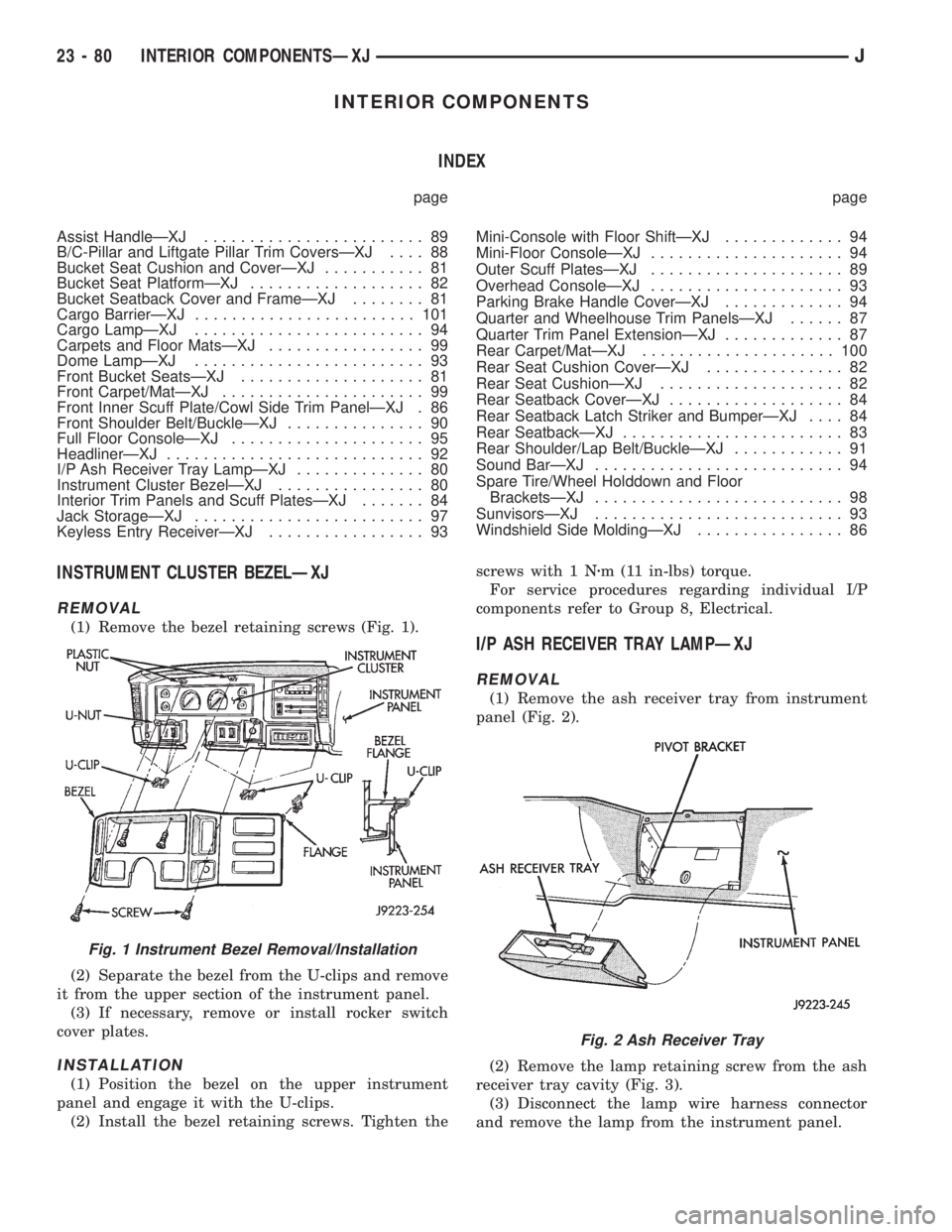
(1) Remove the bezel retaining screws (Fig. 1).
(2) Separate the bezel from the U-clips and remove
it from the upper section of the instrument panel.
(3) If necessary, remove or install rocker switch
cover plates.
INSTALLATION
(1) Position the bezel on the upper instrument
panel and engage it with the U-clips.
(2) Install the bezel retaining screws. Tighten thescrews with 1 Nzm (11 in-lbs) torque.
For service procedures regarding individual I/P
components refer to Group 8, Electrical.
I/P ASH RECEIVER TRAY LAMPÐXJ
REMOVAL
(1) Remove the ash receiver tray from instrument
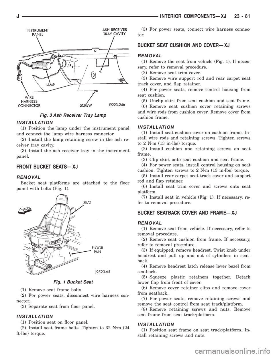
panel (Fig. 2).
(2) Remove the lamp retaining screw from the ash
receiver tray cavity (Fig. 3).
(3) Disconnect the lamp wire harness connector
and remove the lamp from the instrument panel.
Fig. 1 Instrument Bezel Removal/Installation
Fig. 2 Ash Receiver Tray
23 - 80 INTERIOR COMPONENTSÐXJJ
Page 1999 of 2158
INSTALLATION
(1) Position the lamp under the instrument panel
and connect the lamp wire harness connector.
(2) Install the lamp retaining screw in the ash re-
ceiver tray cavity.
(3) Install the ash receiver tray in the instrument
panel.
FRONT BUCKET SEATSÐXJ
REMOVAL
Bucket seat platforms are attached to the floor
panel with bolts (Fig. 1).
(1) Remove seat frame bolts.
(2) For power seats, disconnect wire harness con-
nector.
(3) Separate seat from floor panel.
INSTALLATION
(1) Position seat on floor panel.
(2) Install seat frame bolts. Tighten to 32 Nzm (24
ft-lbs) torque.(3) For power seats, connect wire harness connec-
tor.
BUCKET SEAT CUSHION AND COVERÐXJ
REMOVAL
(1) Remove the seat from vehicle (Fig. 1). If neces-
sary, refer to removal procedure.
(2) Remove seat trim cover.
(3) Remove wire support rod and rear carpet seat
track cover, and flap retainer.
(4) For power seats, remove control housing from
seat cushion.
(5) Unclip skirt from seat cushion and seat frame.
(6) Remove seat cushion cover retaining screws
and wire rods from cushion cover. Remove cover from
cushion frame.
INSTALLATION
(1) Install seat cushion cover on cushion frame. In-
stall wire rods and retaining screws. Tighten screws
to2Nzm (13 in-lbs) torque.
(2) Install cushion and retaining screws on seat
frame.
(3) Clip skirt onto seat cushion and seat frame.
(4) For power seats, install control housing on seat
cushion. Tighten screws to 2 Nzm (13 in-lbs) torque.
(5) Install rear carpet seat track cover and support
rod and flap retainer.
(6) Install seat trim cover and screws onto seat
platform.
(7) Install seat in vehicle (Fig. 1). If necessary, re-
fer to removal procedure.
BUCKET SEATBACK COVER AND FRAMEÐXJ
REMOVAL
(1) Remove seat from vehicle. If necessary, refer to
removal procedure.
(2) Remove seat cushion from frame. If necessary,
refer to removal procedure.
(3) If equipped, remove headrest. Twist knob under
headrest and pull up and out of cylinders in seat-
back.
(4) Remove headrest latch release lever bezel from
seatback.
(5) Squeeze plastic retainers together. Detach
lower flap from front of cover.
(6) Remove cover retainer clips and remove cover
from seatback.
(7) For power seats, remove retaining screws and
remove the seat control from seat track/platform.
(8) Remove retaining screws and nuts. Remove
seat frame from seat track/platform.
INSTALLATION
(1) Position seat frame on seat track/platform. In-
stall retaining screws and nuts.
Fig. 3 Ash Receiver Tray Lamp
Fig. 1 Bucket Seat
JINTERIOR COMPONENTSÐXJ 23 - 81
Page 2000 of 2158
(2) For power seats, position seat control on seat
track/platform. Install retaining screws. Tighten
screws securely.
(3) Position cover on seatback. Install cover re-
tainer clips.
(4) Attach cover bottom elastic band or attach Vel-
cro flap to front of cover.
(5) Install seatback insert.
(6) Install headrest latch release lever bezel.
(7) Install headrest by pushing it down into seat-
back cylinders.
(8) Install cushion on frame. If necessary, refer to
installation procedure.
(9) Install seat in the vehicle. If necessary, refer to
the installation procedure.
(10) For power seats, test seat operation.
BUCKET SEAT PLATFORMÐXJ
REPLACEMENT
Bucket seat platforms are not repairable. If the
seat platform is damaged, replace platform as a unit.
REAR SEAT CUSHIONÐXJ
REMOVAL
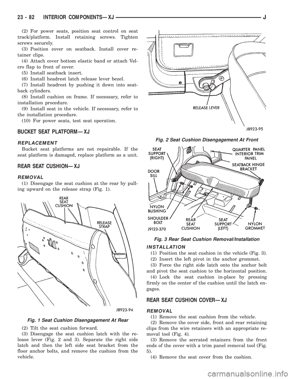
(1) Disengage the seat cushion at the rear by pull-
ing upward on the release strap (Fig. 1).
(2) Tilt the seat cushion forward.
(3) Disengage the seat cushion latch with the re-
lease lever (Fig. 2 and 3). Separate the right side
latch and then the left side seat bracket from the
floor anchor bolts, and remove the cushion from the
vehicle.
INSTALLATION
(1) Position the seat cushion in the vehicle (Fig. 3).
(2) Insert the left pivot in the anchor grommet.
(3) Force the right side latch onto the anchor bolt
and pivot the seat cushion to the horizontal position.
(4) Lock the seat cushion in-place by pressing
firmly on the center of the cushion until the latch en-
gages.
REAR SEAT CUSHION COVERÐXJ
REMOVAL
(1) Remove the seat cushion from the vehicle.
(2) Remove the cover side, front and rear retaining
clips from the wire retainers with an appropriate re-
moval tool (Fig. 4).
(3) Remove the serrated retainers from the front
ends of the cover with a trim panel removal tool (Fig.
5).
(4) Remove the seat cover from the cushion.Fig. 1 Seat Cushion Disengagement At Rear
Fig. 2 Seat Cushion Disengagement At Front
Fig. 3 Rear Seat Cushion Removal/Installation
23 - 82 INTERIOR COMPONENTSÐXJJ