1995 JEEP YJ key
[x] Cancel search: keyPage 352 of 2158
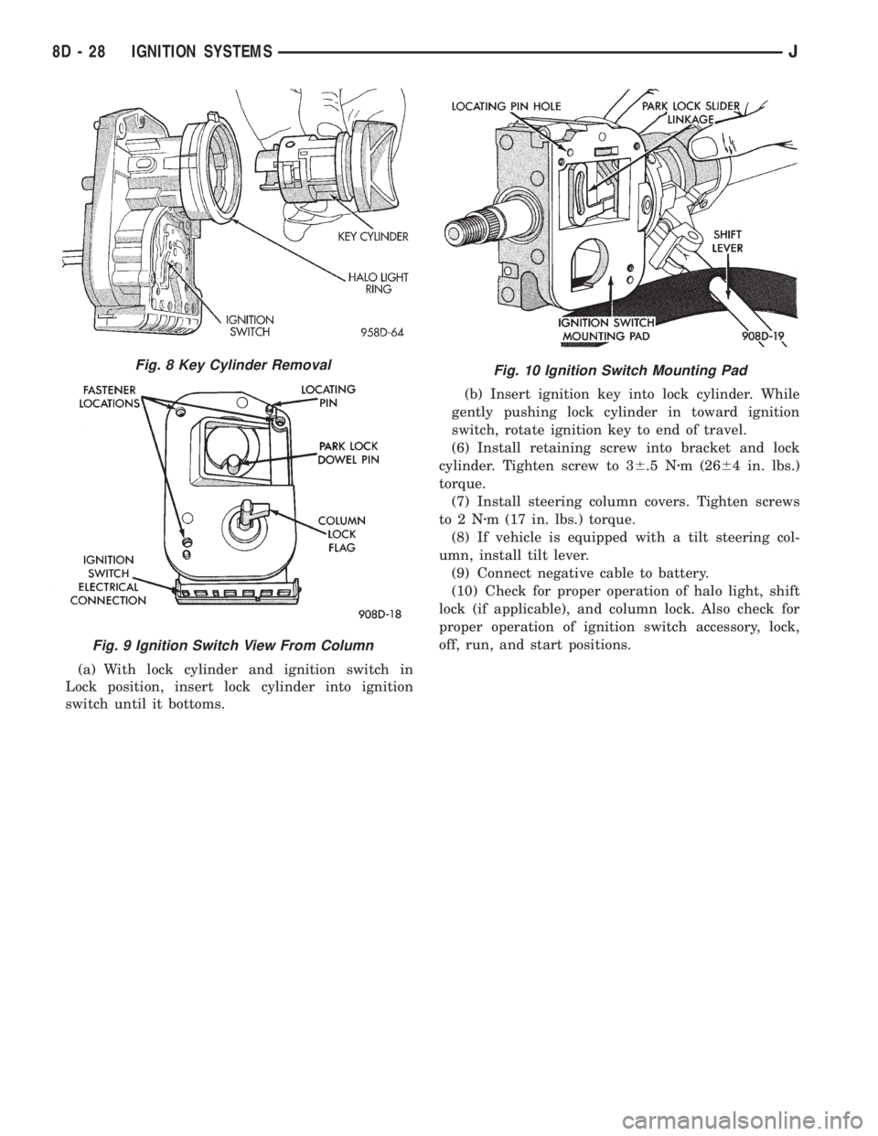
(a) With lock cylinder and ignition switch in
Lock position, insert lock cylinder into ignition
switch until it bottoms.(b) Insert ignition key into lock cylinder. While
gently pushing lock cylinder in toward ignition
switch, rotate ignition key to end of travel.
(6) Install retaining screw into bracket and lock
cylinder. Tighten screw to 36.5 Nzm (2664 in. lbs.)
torque.
(7) Install steering column covers. Tighten screws
to2Nzm (17 in. lbs.) torque.
(8) If vehicle is equipped with a tilt steering col-
umn, install tilt lever.
(9) Connect negative cable to battery.
(10) Check for proper operation of halo light, shift
lock (if applicable), and column lock. Also check for
proper operation of ignition switch accessory, lock,
off, run, and start positions.
Fig. 10 Ignition Switch Mounting PadFig. 8 Key Cylinder Removal
Fig. 9 Ignition Switch View From Column
8D - 28 IGNITION SYSTEMSJ
Page 353 of 2158

IGNITION SWITCHÐYJ MODELS
GENERAL INFORMATION
This section will cover the electrical portion
of the ignition switch. To service the mechani-
cal ignition key switch, refer to Group 19,
Steering.
Refer to Group 8W, Wiring for ignition switch wir-
ing circuits.
The ignition switch is mounted under the instru-
ment panel on the lower section of the steering col-
umn. The headlamp dimmer switch is mounted
beside the ignition switch (Fig. 11). Both of these
switches (ignition and dimmer) share the same
mounting screws.
The switch is connected to the ignition key lock as-
sembly by a remote actuator rod. This remote actua-
tor rod fits into an access hole on the bottom of the
ignition switch (Fig. 12).
REMOVAL
(1) Disconnect the negative battery cable at the
battery.
(2) Remove the windshield wiper intermittent con-
trol module and its bracket (if equipped).
(3) Place the ignition key lock in ACCESSORY po-
sition.
(4) Remove the two headlamp dimmer switch at-
taching nuts. Lift the switch from steering column
while disengaging actuator rod.
Before removing dimmer switch, tape the two
remote control actuator rods (ignition switchand dimmer) to the steering column. This will
prevent accidental disengagement from the up-
per part of the steering column.
(5) Remove the ignition switch-to-steering column
attaching screws.
(6) Disengage the ignition switch from the remote
actuator rod by lifting straight up. Remove switch
from steering column.
(7) Remove wiring from switch as follows:
Two electrical connectors are used to connect all
wiring to the ignition switch. One of the connectors is
installed (interlocked) over the top of the other con-
nector. Remove wiring from switch by disconnecting
the (black) harness connector first and then the other
connector. Remove the switch from the vehicle.
SWITCH TESTING
To test the ignition switch circuity and continuity,
proceed as follows. Place the slide bar (on the igni-
tion switch) (Fig. 12) into the detent position to be
tested. An ohmmeter or continuity light may be used
to check switch continuity. Refer to the Ignition
Switch Continuity Tests chart for continuity tests.
Refer to (Fig. 13) for the lettered/numbered terminal
positions.All wiring must be disconnected from
the ignition switch before performing any con-
tinuity testing.
There are five positions on the ignition switch. The
switch positions (in order) are: ACCESSORY, OFF-
LOCK, OFF, ON AND START (Figs. 14 or 15). Each
position has a detent stop (except START), which isFig. 11 Ignition Switch/Headlamp Dimmer SwitchÐ
Typical
Fig. 12 Ignition Switch/Remote Actuator RodÐ
Typical
JIGNITION SYSTEMS 8D - 29
Page 354 of 2158

spring loaded to release when the key is released.
The maximum voltage drop between any two con-
nected terminals should not exceed 12.5 millivolts
per amp. For example: If a 10 amp load is drawn
through the switch, maximum voltage drop should be
10 x 0.0125 or 0.125 volt.
INSTALLATION/ADJUSTMENT
(1) Place the key lock switch in the ACCESSORY
position.
(2) Place the slider bar (in the ignition switch)
(Fig. 12) into the ACCESSORY detent position.
(3) Connect the wiring to the switch as follows: In-
stall the non-black (colored) connector first and then
the black (colored) connector to the ignition switch.
One connector will interlock the other connector.
(4) Slip the remote actuator rod into the access
hole on the switch (Fig. 12). Install the switch to the
steering column. Be careful not to move the slider
bar (on the switch) out of the ACCESSORY detent
position. Remove the ignition switch actuator rod se-
curing-tape from steering column.
(5) Install the two ignition switch-to-steering col-
umn screws finger tight.Do not tighten screws at
this time.
(6) Adjust ignition switch as follows:
(a) Non-tilt steering column: While holding key
lock switch in ACCESSORY position, gently slide
ignition switchup(towards steering wheel). This
will remove slack from switch. Tighten attaching
screws. Do not allow the ignition switch to move
from the ACCESSORY detent position.
(b) Tilt steering column: While holding the key
lock switch in the ACCESSORY position, gently
slide the ignition switchdown(away from steering
wheel) to remove slack from switch. Tighten at-
taching screws. Do not allow the ignition switch to
move from the ACCESSORY detent position.
Because the ignition switch and the headlamp dim-
mer switch share the same two mounting screws, oneof the screws must be removed from the ignition
switch. This must be doneafterthe ignition switch
has been adjusted andbeforethe dimmer switch
has been installed. Remove one screw.Do notre-
move the stud/nut.
(7) Install the headlamp dimmer switch as follows:
Slip switch into actuator rod and position over the ig-
IGNITION SWITCH CONTINUITY TESTS
Fig. 13 Ignition Switch Terminals/Circuits
8D - 30 IGNITION SYSTEMSJ
Page 456 of 2158
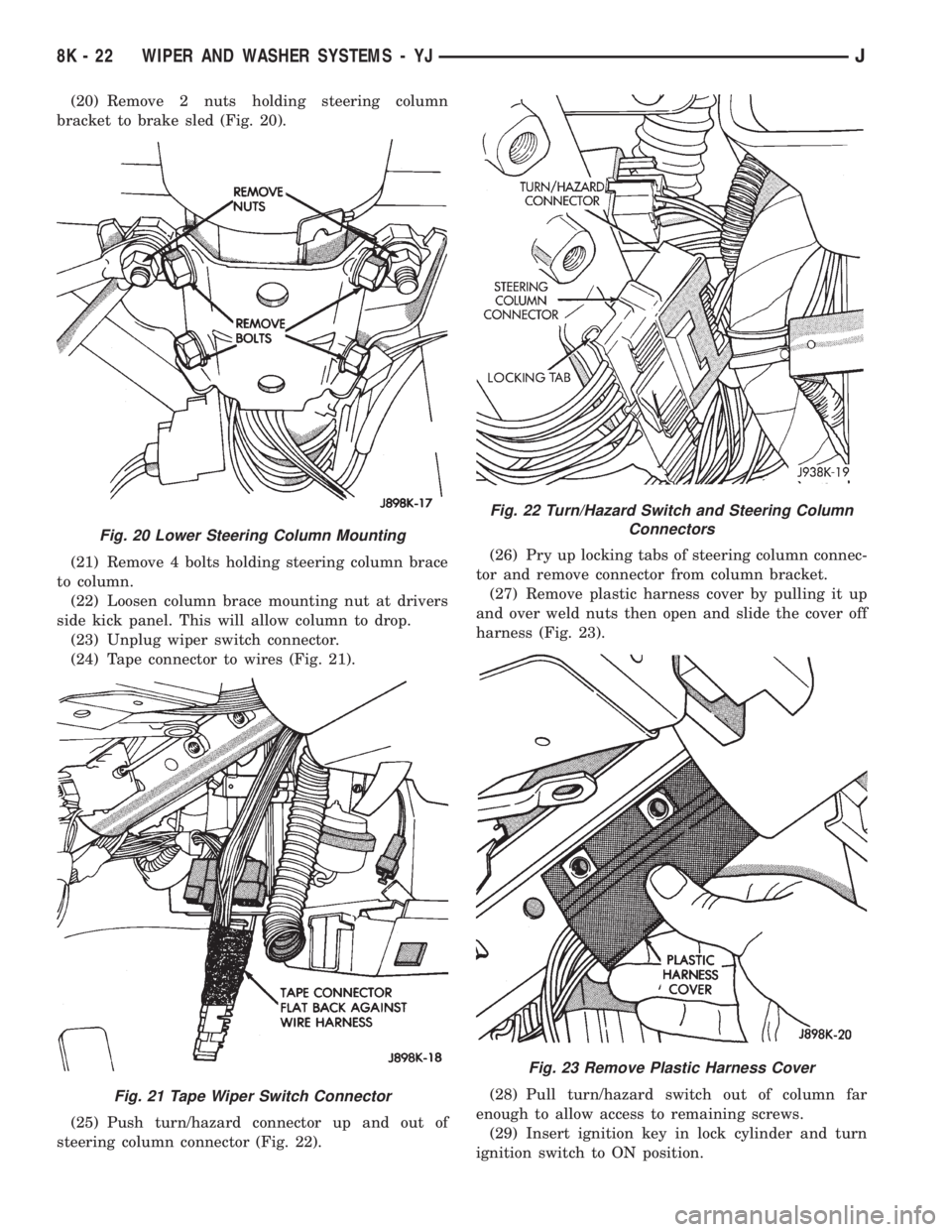
(20) Remove 2 nuts holding steering column
bracket to brake sled (Fig. 20).
(21) Remove 4 bolts holding steering column brace
to column.
(22) Loosen column brace mounting nut at drivers
side kick panel. This will allow column to drop.
(23) Unplug wiper switch connector.
(24) Tape connector to wires (Fig. 21).
(25) Push turn/hazard connector up and out of
steering column connector (Fig. 22).(26) Pry up locking tabs of steering column connec-
tor and remove connector from column bracket.
(27) Remove plastic harness cover by pulling it up
and over weld nuts then open and slide the cover off
harness (Fig. 23).
(28) Pull turn/hazard switch out of column far
enough to allow access to remaining screws.
(29) Insert ignition key in lock cylinder and turn
ignition switch to ON position.
Fig. 20 Lower Steering Column Mounting
Fig. 21 Tape Wiper Switch Connector
Fig. 22 Turn/Hazard Switch and Steering Column
Connectors
Fig. 23 Remove Plastic Harness Cover
8K - 22 WIPER AND WASHER SYSTEMS - YJJ
Page 457 of 2158
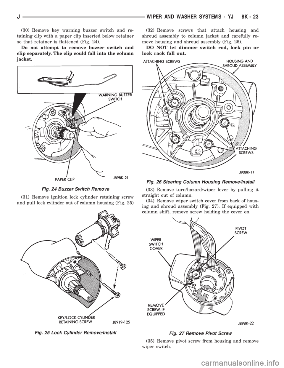
(30) Remove key warning buzzer switch and re-
taining clip with a paper clip inserted below retainer
so that retainer is flattened (Fig. 24).
Do not attempt to remove buzzer switch and
clip separately. The clip could fall into the column
jacket.
(31) Remove ignition lock cylinder retaining screw
and pull lock cylinder out of column housing (Fig. 25)(32) Remove screws that attach housing and
shroud assembly to column jacket and carefully re-
move housing and shroud assembly (Fig. 26).
DO NOT let dimmer switch rod, lock pin or
lock rack fall out.
(33) Remove turn/hazard/wiper lever by pulling it
straight out of column.
(34) Remove wiper switch cover from back of hous-
ing and shroud assembly (Fig. 27). If equipped with
column shift, remove screw holding the cover on.
(35) Remove pivot screw from housing and remove
wiper switch.
Fig. 24 Buzzer Switch Remove
Fig. 25 Lock Cylinder Remove/Install
Fig. 26 Steering Column Housing Remove/Install
Fig. 27 Remove Pivot Screw
JWIPER AND WASHER SYSTEMS - YJ 8K - 23
Page 458 of 2158
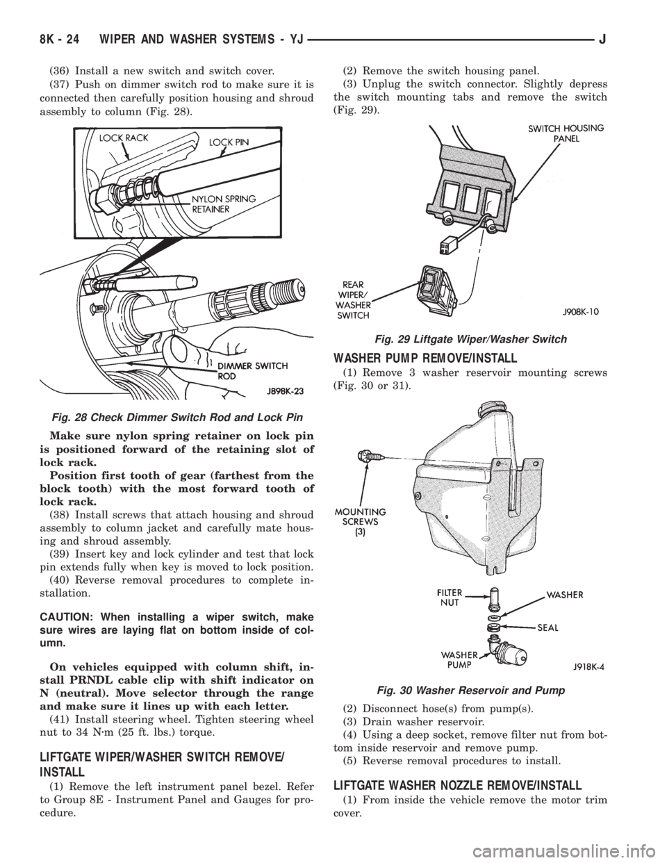
(36) Install a new switch and switch cover.
(37) Push on dimmer switch rod to make sure it is
connected then carefully position housing and shroud
assembly to column (Fig. 28).
Make sure nylon spring retainer on lock pin
is positioned forward of the retaining slot of
lock rack.
Position first tooth of gear (farthest from the
block tooth) with the most forward tooth of
lock rack.
(38) Install screws that attach housing and shroud
assembly to column jacket and carefully mate hous-
ing and shroud assembly.
(39) Insert key and lock cylinder and test that lock
pin extends fully when key is moved to lock position.
(40) Reverse removal procedures to complete in-
stallation.
CAUTION: When installing a wiper switch, make
sure wires are laying flat on bottom inside of col-
umn.
On vehicles equipped with column shift, in-
stall PRNDL cable clip with shift indicator on
N (neutral). Move selector through the range
and make sure it lines up with each letter.
(41) Install steering wheel. Tighten steering wheel
nut to 34 Nzm (25 ft. lbs.) torque.
LIFTGATE WIPER/WASHER SWITCH REMOVE/
INSTALL
(1) Remove the left instrument panel bezel. Refer
to Group 8E - Instrument Panel and Gauges for pro-
cedure.(2) Remove the switch housing panel.
(3) Unplug the switch connector. Slightly depress
the switch mounting tabs and remove the switch
(Fig. 29).
WASHER PUMP REMOVE/INSTALL
(1) Remove 3 washer reservoir mounting screws
(Fig. 30 or 31).
(2) Disconnect hose(s) from pump(s).
(3) Drain washer reservoir.
(4) Using a deep socket, remove filter nut from bot-
tom inside reservoir and remove pump.
(5) Reverse removal procedures to install.
LIFTGATE WASHER NOZZLE REMOVE/INSTALL
(1) From inside the vehicle remove the motor trim
cover.
Fig. 28 Check Dimmer Switch Rod and Lock Pin
Fig. 29 Liftgate Wiper/Washer Switch
Fig. 30 Washer Reservoir and Pump
8K - 24 WIPER AND WASHER SYSTEMS - YJJ
Page 501 of 2158

POWER LOCKS
CONTENTS
page page
DIAGNOSIS............................. 2
GENERAL INFORMATION.................. 1SERVICE PROCEDURES................... 8
GENERAL INFORMATION
Power locks are optional equipment on XJ (Chero-
kee) models. Power windows and the keyless entry
system are included on vehicles equipped with the
power lock option. All doors and the liftgate can be
locked and unlocked electrically by operating the
switch on either front door panel, or by operating the
lock and unlock buttons of the remote keyless entry
transmitter. The power lock and keyless entry sys-
tems operate with battery power supplied indepen-
dent of the ignition switch.
Following are general descriptions of the major
components in the power lock system. Refer to Group
8W - Wiring Diagrams for complete circuit descrip-
tions and diagrams. Refer to the owner's manual for
more information on the features and use of these
systems.
POWER LOCK SWITCH
The power locks are controlled by a two-way switch
mounted on the trim panel of each front door. The
switch controls battery feed to the lock and unlock
relays. The door lock switches can not be repaired. If
faulty, the entire switch must be replaced.
POWER LOCK/UNLOCK RELAYS
The power lock and unlock relays are located in the
relay center. The relay center is located on the lower
instrument panel reinforcement behind the lower in-
strument panel and just right of the steering column.
The relays respond to inputs from the power lock
switches and the keyless entry module by sending
the correct battery and ground feeds to the lock mo-
tors. The lock and unlock relays can not be repaired.
If faulty, they must be replaced.
POWER LOCK MOTOR
The locks are actuated by a reversible motor
mounted within each door. The motor direction iscontrolled by the battery and ground feeds from the
power lock/unlock relays. The motor can not be re-
paired. If faulty, the entire motor must be replaced.
KEYLESS ENTRY TRANSMITTER
The keyless entry transmitter is equipped with two
buttons labeled Lock and Unlock. It is also designed
to serve as a key fob and is equipped with a key ring.
Each transmitter has a different vehicle access code,
which must be programmed into the memory of the
keyless entry module in the vehicle in order to oper-
ate the locks. The operating range of the infrared
transmitter signal is up to 4.75 meters (15 feet) from
the receiver.
The transmitter operates on two CR1616 3-volt (or
equivalent) batteries. Typical battery life is from one
to two years.
KEYLESS ENTRY MODULE
The keyless entry module is mounted in a housing
on the headliner near the windshield between the
sunvisors, or inside and towards the rear of the over-
head console (if equipped). This module contains the
keyless entry receiver and program logic for the key-
less entry system.
The keyless entry module has a memory function
to retain the vehicle access code of at least one, and
up to four transmitters. The module receives input
from the remote keyless entry transmitter. In re-
sponse to that input, it is programmed to control out-
puts to the lock and unlock relays. The module can
not be repaired and, if faulty, must be replaced.
JPOWER LOCKS 8P - 1
Page 502 of 2158
DIAGNOSIS
As a preliminary system diagnosis, note system op-
eration while you actuate both the Lock and Unlock
functions with the power lock switches and the key-
less entry transmitter. Then, proceed as follows:
²If system fails to function with either the switches
or the transmitter, see Power Lock System diagnosis.
²If system functions with both switches, but not the
transmitter, see Keyless Entry Transmitter diagnosis.
²If system functions with transmitter, but not with
one or both switches, see Power Lock System diagno-
sis.
²If one lock fails to operate with the switches or
transmitter, see Power Lock Motor diagnosis.
POWER LOCK SYSTEM
(1) Inspect fuse 13 in fuseblock module. Replace if
necessary. If OK, measure voltage at battery side of
fuse. There should be 12 volts. If not OK, repair open
from Power Distribution Center.
(2) Remove door switch(es) and measure voltage at
terminal 1. Meter should read battery voltage. If OK,
go to next step. If not OK, repair open to fuse 9 in
fuseblock module.
(3) Check door switch continuity as shown in the
applicable charts on the following pages. If OK, go to
next step. If not OK, replace switch.
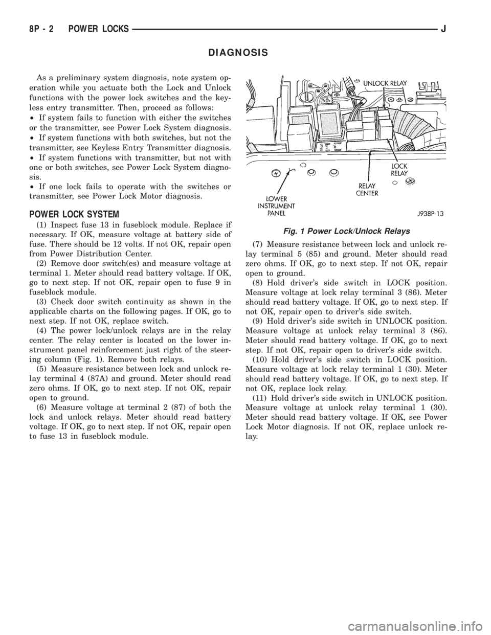
(4) The power lock/unlock relays are in the relay
center. The relay center is located on the lower in-
strument panel reinforcement just right of the steer-
ing column (Fig. 1). Remove both relays.
(5) Measure resistance between lock and unlock re-
lay terminal 4 (87A) and ground. Meter should read
zero ohms. If OK, go to next step. If not OK, repair
open to ground.
(6) Measure voltage at terminal 2 (87) of both the
lock and unlock relays. Meter should read battery
voltage. If OK, go to next step. If not OK, repair open
to fuse 13 in fuseblock module.(7) Measure resistance between lock and unlock re-
lay terminal 5 (85) and ground. Meter should read
zero ohms. If OK, go to next step. If not OK, repair
open to ground.
(8) Hold driver's side switch in LOCK position.
Measure voltage at lock relay terminal 3 (86). Meter
should read battery voltage. If OK, go to next step. If
not OK, repair open to driver's side switch.
(9) Hold driver's side switch in UNLOCK position.
Measure voltage at unlock relay terminal 3 (86).
Meter should read battery voltage. If OK, go to next
step. If not OK, repair open to driver's side switch.
(10) Hold driver's side switch in LOCK position.
Measure voltage at lock relay terminal 1 (30). Meter
should read battery voltage. If OK, go to next step. If
not OK, replace lock relay.
(11) Hold driver's side switch in UNLOCK position.
Measure voltage at unlock relay terminal 1 (30).
Meter should read battery voltage. If OK, see Power
Lock Motor diagnosis. If not OK, replace unlock re-
lay.Fig. 1 Power Lock/Unlock Relays
8P - 2 POWER LOCKSJ