1995 JEEP YJ engine oil
[x] Cancel search: engine oilPage 1637 of 2158
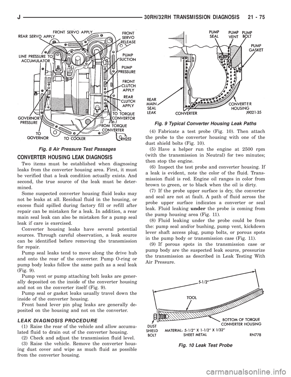
CONVERTER HOUSING LEAK DIAGNOSIS
Two items must be established when diagnosing
leaks from the converter housing area. First, it must
be verified that a leak condition actually exists. And
second, the true source of the leak must be deter-
mined.
Some suspected converter housing fluid leaks may
not be leaks at all. Residual fluid in the housing, or
excess fluid spilled during factory fill or refill after
repair can be mistaken for a leak. In addition, a rear
main seal leak can also be mistaken for a pump seal
leak if care is exercised.
Converter housing leaks have several potential
sources. Through careful observation, a leak source
can be identified before removing the transmission
for repair.
Pump seal leaks tend to move along the drive hub
and onto the rear of the converter. Pump O-ring or
pump body leaks follow the same path as a seal leak
(Fig. 9).
Pump vent or pump attaching bolt leaks are gener-
ally deposited on the inside of the converter housing
and not on the converter itself (Fig. 9).
Pump seal or gasket leaks usually travel down the
inside of the converter housing.
Front band lever pin plug leaks are generally de-
posited on the housing and not on the converter.
LEAK DIAGNOSIS PROCEDURE
(1) Raise the rear of the vehicle and allow accumu-
lated fluid to drain out of the converter housing.
(2) Check and adjust the transmission fluid level.
(3) Raise the vehicle. Remove the converter hous-
ing dust cover and wipe as much fluid as possible
from the converter housing.(4) Fabricate a test probe (Fig. 10). Then attach
the probe to the converter housing with one of the
dust shield bolts (Fig. 10).
(5) Have a helper run the engine at 2500 rpm
(with the transmission in Neutral) for two minutes;
then stop the engine.
(6) Inspect the test probe and converter housing. If
a leak is evident, note the color of the fluid. Trans-
mission fluid is red. Engine oil ranges in color from
brown to green, or to black when the oil is dirty.
(7) If the probe upper surface is dry, the converter
and seal are not at fault. A path of fluid across the
probe upper surface indicates a converter or seal
leak. Fluid leakingunderthe probe is coming from
the pump housing area (Fig. 11).
(8) Fluid leaking under the probe could be from
the: pump seal and/or bushing, pump vent, kickdown
lever shaft access plug, pump bolts, or porous spots
in the pump body or transmission case (Fig. 11).
(9) If porous spots in the transmission case or
pump body are the suspected leak source, pressurize
the transmission as described in Leak Testing With
Air Pressure.
Fig. 8 Air Pressure Test Passages
Fig. 9 Typical Converter Housing Leak Paths
Fig. 10 Leak Test Probe
J30RH/32RH TRANSMISSION DIAGNOSIS 21 - 75
Page 1661 of 2158
30RH/32RH IN-VEHICLE SERVICE
INDEX
page page
Converter Drainback Check Valve Service...... 113
Fluid and Filter Replacement................. 99
Fluid Level Check......................... 99
Front Band Adjustment.................... 102
Governor and Park Gear Service............. 105
Oil Filter Replacement..................... 103
Park Interlock Cable Adjustment (XJ).......... 101
Park Lock Component Replacement.......... 108
Park/Neutral Position Switch Service.......... 109
Rear Band Adjustment.................... 103
Recommended Fluid....................... 99Refilling After Overhaul or Fluid/Filter Change . . . 100
Shift Cable Adjustment (XJ)................. 100
Shift Linkage Adjustment (YJ)............... 100
Speedometer Service..................... 109
Throttle Valve Cable Adjustment (XJ/YJ)....... 101
Transmission Cooler Flow Testing............ 113
Transmission Cooler Line and Fitting Service.... 111
Transmission Cooler Reverse Flushing......... 114
Valve Body Installation.................... 104
Valve Body Removal...................... 104
Valve Body Service....................... 104
RECOMMENDED FLUID
Recommended (and preferred) fluid for 30RH/32RH
transmissions is Mopar ATF Plus, type 7176.
Dexron II is not really recommended and should
only be used when ATF Plus is not available.
FLUID LEVEL CHECK
Transmission fluid level should be checked monthly
under normal operation. If the vehicle is used for
trailer towing or similar heavy load hauling, check
fluid level and condition weekly.
Fluid level is checked with the engine running at
curb idle speed, the transmission in Neutral and the
transmission fluid at normal operating temperature.
FLUID LEVEL CHECK PROCEDURE
(1) Transmission fluid must be at normal operating
temperature for accurate fluid level check. Drive ve-
hicle if necessary to bring fluid temperature up to
normal hot operating temperature of 82ÉC (180ÉF).
(2) Position vehicle on level surface. This is ex-
tremely important for accurate fluid level check.
(3) Start and run engine at curb idle speed.
(4) Apply parking brakes.
(5) Shift transmission momentarily into all gear
ranges. Then shift transmission back to Neutral.
(6) Clean top of filler tube and dipstick to keep dirt
from entering tube.
(7) Remove dipstick and check fluid level as fol-
lows:
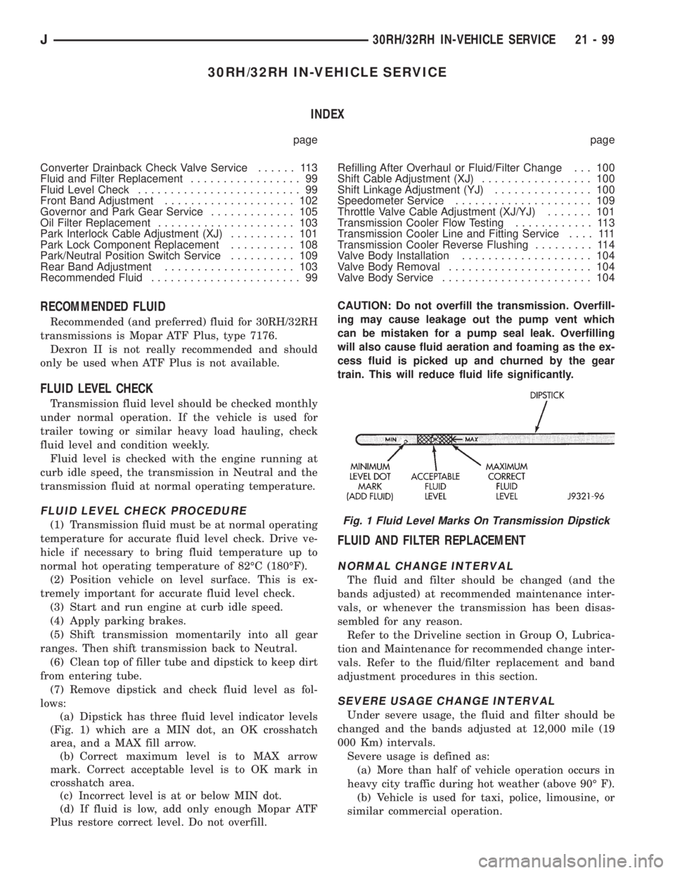
(a) Dipstick has three fluid level indicator levels
(Fig. 1) which are a MIN dot, an OK crosshatch
area, and a MAX fill arrow.
(b) Correct maximum level is to MAX arrow
mark. Correct acceptable level is to OK mark in
crosshatch area.
(c) Incorrect level is at or below MIN dot.
(d) If fluid is low, add only enough Mopar ATF
Plus restore correct level. Do not overfill.CAUTION: Do not overfill the transmission. Overfill-
ing may cause leakage out the pump vent which
can be mistaken for a pump seal leak. Overfilling
will also cause fluid aeration and foaming as the ex-
cess fluid is picked up and churned by the gear
train. This will reduce fluid life significantly.
FLUID AND FILTER REPLACEMENT
NORMAL CHANGE INTERVAL
The fluid and filter should be changed (and the
bands adjusted) at recommended maintenance inter-
vals, or whenever the transmission has been disas-
sembled for any reason.
Refer to the Driveline section in Group O, Lubrica-
tion and Maintenance for recommended change inter-
vals. Refer to the fluid/filter replacement and band
adjustment procedures in this section.
SEVERE USAGE CHANGE INTERVAL
Under severe usage, the fluid and filter should be
changed and the bands adjusted at 12,000 mile (19
000 Km) intervals.
Severe usage is defined as:
(a) More than half of vehicle operation occurs in
heavy city traffic during hot weather (above 90É F).
(b) Vehicle is used for taxi, police, limousine, or
similar commercial operation.
Fig. 1 Fluid Level Marks On Transmission Dipstick
J30RH/32RH IN-VEHICLE SERVICE 21 - 99
Page 1662 of 2158
(c) Vehicle is used for trailer towing or heavy
load hauling.
FLUID/FILTER REPLACEMENT PROCEDURE
(1) Raise vehicle.
(2) Remove oil pan and drain fluid.
(3) Clean oil pan and pan magnet. Then clean re-
maining gasket material from gasket surface of
transmission case.
(4) Remove fluid filter screws and remove filter.
(5) Position new filter on valve body and install fil-
ter screws. Tighten screws to 4 Nzm (35 in. lbs.)
torque.
(6) Adjust rear band at this time if required.
(7) Position new gasket on oil pan and install pan
on transmission. Tighten pan bolts to 150 in. lbs. (17
Nzm) torque.
(8) Adjust front band at this time if required.
(9) Lower vehicle and refill transmission with Mo-
par ATF Plus, type 7176 fluid.
REFILLING AFTER OVERHAUL OR FLUID/FILTER
CHANGE
The most effective way to avoid overfilling after a
fluid change or overhaul is as follows:
(1) Remove dipstick and insert clean funnel in
transmission fill tube.
(2) Add following initial quantity of Mopar ATF
Plus to transmission:
(a) If only fluid and filter were changed, add3
pints (1-1/2 quarts)of ATF Plus to transmission.
(b) If transmission was completely overhauled
and torque converter was replaced or drained, add
10 pints (5 quarts)of ATF Plus to transmission.
(3) Apply parking brakes.
(4) Start and run engine at normal curb idle speed.
(5) Apply service brakes, shift transmission
through all gear ranges then back to Neutral, and
leave engine running at curb idle speed.
(6) Remove funnel, insert dipstick and check fluid
level. Add only enough fluid to bring level toMIN
dot mark on dipstick.
(7) Drive vehicle until transmission fluid is at nor-
mal operating temperature. Then recheck fluid level
as described in next step.
(8) Leave engine running at curb idle speed, shift
into Neutral, and check fluid level again. This time,
add just enough fluid to bring level up toMAX ar-
row mark but do not overfill.
(9) When fluid level is correct, shut engine off, re-
lease park brake, remove funnel, and reseat dipstick
in fill tube.
SHIFT LINKAGE ADJUSTMENT (YJ)
(1) Check linkage adjustment by starting engine in
Park and Neutral.(2) Adjustment is OK if engine starts only in park
and Neutral. Adjustment is incorrect if engine starts
in one but not both positions.
(3) If engine starts in any position other than Park
or Neutral, or if engine will not start at all, park/
neutral position switch may be faulty.
(4) Shift transmission into Park.
(5) Raise vehicle.
(6) Check condition of shift rods, bellcrank,
bellcrank brackets and linkage bushings/grommets
(Fig. 2). Tighten, repair, replace worn, damaged
parts. Do not attempt adjustment if linkage compo-
nents are worn or damaged.
(7) Loosen shift rod trunnion lock bolt or nut. Be
sure upper shift rod slides freely in trunnion (Fig. 2).
Also be sure shift rods and bellcrank rotate freely
and do not bind at any point.
(8) Verify that manual lever is in Park detent (Fig.
2). Move lever all the way rearward to be sure it is in
Park.
(9) Check for positive engagement of park lock by
attempting to rotate propeller shaft. Shaft will not
turn when park pawl is engaged.
(10) Adjust shift rod trunnion to a obtain free pin
fit in bellcrank arm and tighten trunnion lock bolt or
nut. Prevent shift rod from turning while tightening
bolt or nut. Gearshift linkage lash must be elimi-
nated to obtain proper adjustment. Eliminate lash by
pulling downward on shift rod and pressing upward
on bellcrank.
(11) Confirm proper adjustment by starting engine
in Park and Neutral. Engine should start in these
positions only.If engine starts in any position
other than Park or Neutral, adjustment is in-
correct or neutral switch is faulty.
(12) Lower vehicle and verify that steering lock op-
erates correctly.
SHIFT CABLE ADJUSTMENT (XJ)
(1) Shift transmission into Park.
(2) Raise vehicle.
(3) Release cable adjuster clamp to unlock cable
(Figs. 3 and 4). Clamp is at transmission end of ca-
ble.
(4) Unsnap cable from transmission cable bracket.
(5) Move transmission shift lever fully rearward to
Park detent. Lever is on manual valve shaft at driver
side of case.
(6) Verify positive engagement of park lock by at-
tempting to rotate propeller shaft. Shaft will not ro-
tate when park lock is engaged.
(7) Snap cable into cable bracket.
(8) Lock shift cable by pressing cable adjuster
clamp down until it snaps into place.
(9) Check engine starting. Engine should start only
in Park and Neutral.
(10) Lower vehicle.
21 - 100 30RH/32RH IN-VEHICLE SERVICEJ
Page 1675 of 2158
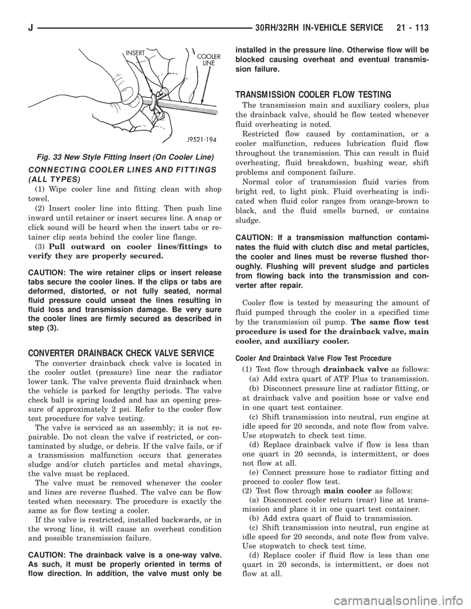
CONNECTING COOLER LINES AND FITTINGS
(ALL TYPES)
(1) Wipe cooler line and fitting clean with shop
towel.
(2) Insert cooler line into fitting. Then push line
inward until retainer or insert secures line. A snap or
click sound will be heard when the insert tabs or re-
tainer clip seats behind the cooler line flange.
(3)Pull outward on cooler lines/fittings to
verify they are properly secured.
CAUTION: The wire retainer clips or insert release
tabs secure the cooler lines. If the clips or tabs are
deformed, distorted, or not fully seated, normal
fluid pressure could unseat the lines resulting in
fluid loss and transmission damage. Be very sure
the cooler lines are firmly secured as described in
step (3).
CONVERTER DRAINBACK CHECK VALVE SERVICE
The converter drainback check valve is located in
the cooler outlet (pressure) line near the radiator
lower tank. The valve prevents fluid drainback when
the vehicle is parked for lengthy periods. The valve
check ball is spring loaded and has an opening pres-
sure of approximately 2 psi. Refer to the cooler flow
test procedure for valve testing.
The valve is serviced as an assembly; it is not re-
pairable. Do not clean the valve if restricted, or con-
taminated by sludge, or debris. If the valve fails, or if
a transmission malfunction occurs that generates
sludge and/or clutch particles and metal shavings,
the valve must be replaced.
The valve must be removed whenever the cooler
and lines are reverse flushed. The valve can be flow
tested when necessary. The procedure is exactly the
same as for flow testing a cooler.
If the valve is restricted, installed backwards, or in
the wrong line, it will cause an overheat condition
and possible transmission failure.
CAUTION: The drainback valve is a one-way valve.
As such, it must be properly oriented in terms of
flow direction. In addition, the valve must only beinstalled in the pressure line. Otherwise flow will be
blocked causing overheat and eventual transmis-
sion failure.
TRANSMISSION COOLER FLOW TESTING
The transmission main and auxiliary coolers, plus
the drainback valve, should be flow tested whenever
fluid overheating is noted.
Restricted flow caused by contamination, or a
cooler malfunction, reduces lubrication fluid flow
throughout the transmission. This can result in fluid
overheating, fluid breakdown, bushing wear, shift
problems and component failure.
Normal color of transmission fluid varies from
bright red, to light pink. Fluid overheating is indi-
cated when fluid color ranges from orange-brown to
black, and the fluid smells burned, or contains
sludge.
CAUTION: If a transmission malfunction contami-
nates the fluid with clutch disc and metal particles,
the cooler and lines must be reverse flushed thor-
oughly. Flushing will prevent sludge and particles
from flowing back into the transmission and con-
verter after repair.
Cooler flow is tested by measuring the amount of
fluid pumped through the cooler in a specified time
by the transmission oil pump.The same flow test
procedure is used for the drainback valve, main
cooler, and auxiliary cooler.
Cooler And Drainback Valve Flow Test Procedure
(1) Test flow throughdrainback valveas follows:
(a) Add extra quart of ATF Plus to transmission.
(b) Disconnect pressure line at radiator fitting, or
at drainback valve and position hose or valve end
in one quart test container.
(c) Shift transmission into neutral, run engine at
idle speed for 20 seconds, and note flow from valve.
Use stopwatch to check test time.
(d) Replace drainback valve if flow is less than
one quart in 20 seconds, is intermittent, or does
not flow at all.
(e) Connect pressure hose to radiator fitting and
proceed to cooler flow test.
(2) Test flow throughmain cooleras follows:
(a) Disconnect cooler return (rear) line at trans-
mission and place it in one quart test container.
(b) Add extra quart of fluid to transmission.
(c) Shift transmission into neutral, run engine at
idle speed for 20 seconds, and note flow from valve.
Use stopwatch to check test time.
(d) Replace cooler if fluid flow is less than one
quart in 20 seconds, is intermittent, or does not
flow at all.
Fig. 33 New Style Fitting Insert (On Cooler Line)
J30RH/32RH IN-VEHICLE SERVICE 21 - 113
Page 1678 of 2158
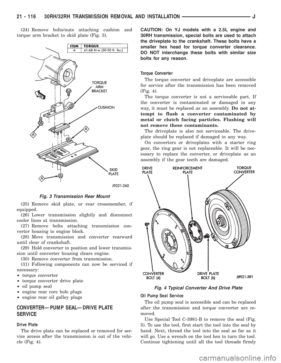
(24) Remove bolts/nuts attaching cushion and
torque arm bracket to skid plate (Fig. 3).
(25) Remove skid plate, or rear crossmember, if
equipped.
(26) Lower transmission slightly and disconnect
cooler lines at transmission.
(27) Remove bolts attaching transmission con-
verter housing to engine block.
(28) Move transmission and converter rearward
until clear of crankshaft.
(29) Hold converter in position and lower transmis-
sion until converter housing clears engine.
(30) Remove converter from transmission.
(31) Following components can now be serviced if
necessary:
²torque converter
²torque converter drive plate
²oil pump seal
²engine rear core hole plugs
²engine rear oil galley plugs
CONVERTERÐPUMP SEALÐDRIVE PLATE
SERVICE
Drive Plate
The drive plate can be replaced or removed for ser-
vice access after the transmission is out of the vehi-
cle (Fig. 4).CAUTION: On YJ models with a 2.5L engine and
30RH transmission, special bolts are used to attach
the driveplate to the crankshaft. These bolts have a
smaller hex head for torque converter clearance.
DO NOT interchange these bolts with similar size
bolts for any reason.
Torque Converter
The torque converter and driveplate are accessible
for service after the transmission has been removed
(Fig. 4).
The torque converter is not a serviceable part. If
the converter is contaminated or damaged in any
way, it must be replaced as an assembly.Do not at-
tempt to flush a converter contaminated by
metal or clutch facing particles. Flushing will
not remove these contaminants.
The driveplate is also not serviceable. The drive-
plate should be replaced if damaged in any way.
On converters or driveplates with a starter ring
gear, the ring gear is not replaceable. It will be nec-
essary to replace the converter, or driveplate as an
assembly if the gear teeth are damaged.
Oil Pump Seal Service
The oil pump seal is accessible and can be replaced
after the transmission and torque converter are re-
moved.
Use Special Tool C-3981-B to remove the seal (Fig.
5). To use the tool, first start the tool into the seal by
hand. Next, thread the tool into the seal as far as it
will go. Use a wrench on the tool hex to turn the tool.
Continue tightening until all the tool threads firmly
Fig. 3 Transmission Rear Mount
Fig. 4 Typical Converter And Drive Plate
21 - 116 30RH/32RH TRANSMISSION REMOVAL AND INSTALLATIONJ
Page 1727 of 2158
AW-4 AUTOMATIC TRANSMISSION
CONTENTS
page page
AW-4 AUTOMATIC TRANSMISSION........ 165
AW-4 IN-VEHICLE SERVICE.............. 182
AW-4 TRANSMISSION DIAGNOSIS......... 176
AW-4 TRANSMISSION OVERHAUL......... 201AW-4 TRANSMISSION REMOVAL AND
INSTALLATION....................... 198
GENERAL INFORMATION................ 165
GENERAL INFORMATION
INDEX
page page
Components and Operation................. 166
Description............................. 165
First/Second/Third/Reverse Components....... 168
Fourth Gear Overdrive Components.......... 167
Geartrain Operation and Application Charts..... 169Hydraulic System........................ 169
Recommended Fluid and Capacity........... 166
Torque Converter........................ 167
Transmission Identification.................. 166
Transmission Ranges and Shift Lever Positions . . 166
DESCRIPTION
AW-4 Transmission Overhaul
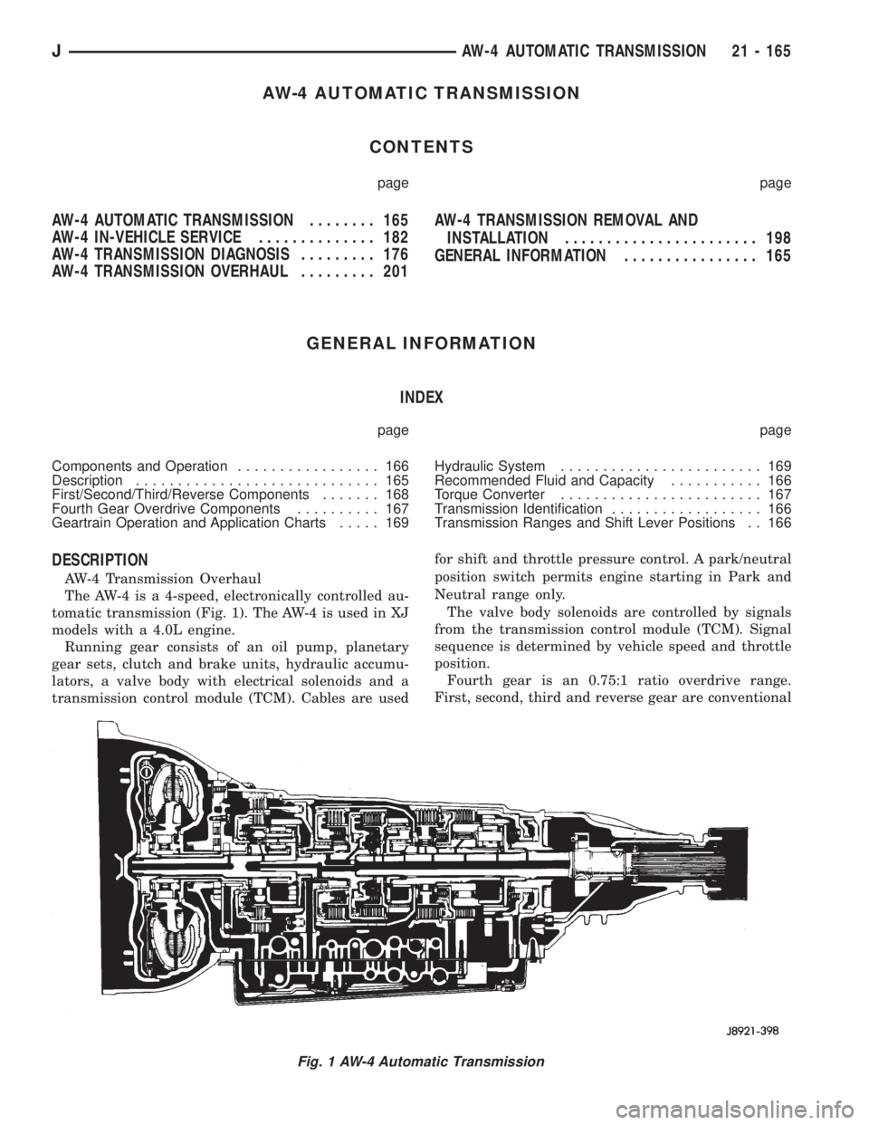
The AW-4 is a 4-speed, electronically controlled au-
tomatic transmission (Fig. 1). The AW-4 is used in XJ
models with a 4.0L engine.
Running gear consists of an oil pump, planetary
gear sets, clutch and brake units, hydraulic accumu-
lators, a valve body with electrical solenoids and a
transmission control module (TCM). Cables are usedfor shift and throttle pressure control. A park/neutral
position switch permits engine starting in Park and
Neutral range only.
The valve body solenoids are controlled by signals
from the transmission control module (TCM). Signal
sequence is determined by vehicle speed and throttle
position.
Fourth gear is an 0.75:1 ratio overdrive range.
First, second, third and reverse gear are conventional
Fig. 1 AW-4 Automatic Transmission
JAW-4 AUTOMATIC TRANSMISSION 21 - 165
Page 1732 of 2158

The manual valve, 1-2 shift valve, primary regula-
tor valve, accumulator control valve, check balls, so-
lenoids and oil strainers are located in the lower
body section (Fig. 10). The remaining control and
shift valves plus check balls and one additional oil
strainer are located in the upper body section (Fig.
11).
Manual Valve
The manual valve is operated by the gearshift link-
age. The valve diverts fluid to the apply circuits ac-
cording to shift lever position.Primary Regulator Valve
The primary regulator valve (Fig. 13) modulates
line pressure to the clutches and brakes according to
engine load. The valve is actuated by throttle valve
pressure.
During high load operation, the valve increases line
pressure to maintain positive clutch and brake en-
gagement. At light load, the valve decreases line
pressure just enough to maintain smooth engage-
ment.
Fig. 10 Upper Body Components
Fig. 11 Lower Body Components
21 - 170 AW-4 AUTOMATIC TRANSMISSIONJ
Page 1740 of 2158
PRESSURE TEST ANALYSIS
If pressures in D and Reverse are higher than
specified in test, check for the following:
²throttle cable loose, worn, binding or out of adjust-
ment
²throttle valve, downshift plug, throttle cam, or pri-
mary regulator valve are sticking, worn or damaged
If pressures in D and Reverse are lower than spec-
ified in test, check for following:
²throttle cable loose, worn, binding or out of adjust-
ment
²throttle valve, downshift plug, or throttle cam
sticking, worn or damaged
²primary regulator valve sticking, worn, or dam-
aged
²oil pump gears or housing worn, or damaged
²overdrive clutch worn, or damaged
If pressures are low in D range only, check for fol-
lowing:
²forward clutch worn or damaged
²fluid leakage in D range circuit (component seal
and O-rings)
If pressures are low in Reverse only, check for fol-
lowing:
²shift cable and manual valve out of adjustment
²fluid leakage in reverse circuit (component seal
and O-rings)
²direct clutch worn or damaged
²first/reverse brake worn or damaged
TORQUE CONVERTER STALL TEST
Stall testing checks the holding ability of the trans-
mission clutches and brakes and of the torque con-
verter stator overrunning clutch.Stall speeds are
checked in both Drive and Reverse ranges with
the AW-4 transmission.
(1) Before starting test, be sure fluid level is cor-
rect and fluid is at normal operating temperature.
(2) Connect tachometer to engine. Position tachom-
eter so it can be viewed from drivers seat.
(3) Apply parking brakes and block wheels.
(4) Apply and hold service brakes.
(5) Shift transfer case into 2H position.
(6) Start engine.
WARNING: DO NOT ALLOW ANYONE TO STAND AT
THE FRONT OR REAR OF THE VEHICLE DURING
THE TEST.
(7) Shift transmission into D range.
(8) Open throttle completely and record maximum
engine rpm registered on tachometer. It takes any-
where from 4 to 10 seconds to reach maximum rpm.
However, once maximum rpm has been achieved,do
not hold wide open throttle for more than 3-4
seconds.CAUTION: Stalling the converter causes a rapid in-
crease in fluid temperature. To avoid fluid overheat-
ing, hold wide open throttle for no more than 4
seconds after reaching peak rpm. In addition, if
more than one stall test is required, run the engine
at 1000 rpm with the transmission in Neutral for at
least 20 seconds to cool the fluid.
(9) Stall speed should be in 2100-2400 rpm range
in Drive.
(10) Release throttle, shift transmission into Neu-
tral, and run engine for 20-30 seconds to cool fluid.
(11) Shift transmission into Reverse.
(12) Repeat stall test described in step (8).
(13) Stall speed in Reverse should also be in 2100-
2400 rpm range.
(14) Release accelerator pedal, shift transmission
into Neutral, and run engine for 20-30 seconds to
cool fluid.
STALL SPEED TEST ANALYSIS
If engine rpm is lower than specified in D and Re-
verse, check for the following:
²engine output/performance insufficient
²stator overrunning clutch in torque converter not
holding if engine speed was 1500 rpm or less.
If stall speed in D range is higher than specified,
check for the following:
²line pressure low
²forward clutch slipping
²No. 2 one-way clutch not holding
²overdrive one-way clutch not holding
If stall speed in Reverse was higher than specified,
check for the following:
²line pressure low
²direct clutch slipping
²first/ reverse brake slipping
²overdrive one-way clutch not holding
If stall speeds were higher than specified in both D
and Reverse, check for the following:
²low fluid level
²line pressure low
²overdrive one-way clutch not holding
TIME LAG TEST
This test checks general condition of the overdrive
clutch, forward clutch, rear clutch and first/reverse
brake. Condition is indicated by the amount of time
required for clutch/brake engagement with the en-
gine at curb idle speed. Engagement time is mea-
sured for D and Reverse positions. A stop watch is
recommended for test accuracy.
TEST PROCEDURE
(1) Check and adjust transmission fluid level if
necessary.
(2) Bring transmission to normal operating tem-
perature.
21 - 178 AW-4 TRANSMISSION DIAGNOSISJ