1995 JEEP YJ check engine
[x] Cancel search: check enginePage 1740 of 2158
PRESSURE TEST ANALYSIS
If pressures in D and Reverse are higher than
specified in test, check for the following:
²throttle cable loose, worn, binding or out of adjust-
ment
²throttle valve, downshift plug, throttle cam, or pri-
mary regulator valve are sticking, worn or damaged
If pressures in D and Reverse are lower than spec-
ified in test, check for following:
²throttle cable loose, worn, binding or out of adjust-
ment
²throttle valve, downshift plug, or throttle cam
sticking, worn or damaged
²primary regulator valve sticking, worn, or dam-
aged
²oil pump gears or housing worn, or damaged
²overdrive clutch worn, or damaged
If pressures are low in D range only, check for fol-
lowing:
²forward clutch worn or damaged
²fluid leakage in D range circuit (component seal
and O-rings)
If pressures are low in Reverse only, check for fol-
lowing:
²shift cable and manual valve out of adjustment
²fluid leakage in reverse circuit (component seal
and O-rings)
²direct clutch worn or damaged
²first/reverse brake worn or damaged
TORQUE CONVERTER STALL TEST
Stall testing checks the holding ability of the trans-
mission clutches and brakes and of the torque con-
verter stator overrunning clutch.Stall speeds are
checked in both Drive and Reverse ranges with
the AW-4 transmission.
(1) Before starting test, be sure fluid level is cor-
rect and fluid is at normal operating temperature.
(2) Connect tachometer to engine. Position tachom-
eter so it can be viewed from drivers seat.
(3) Apply parking brakes and block wheels.
(4) Apply and hold service brakes.
(5) Shift transfer case into 2H position.
(6) Start engine.
WARNING: DO NOT ALLOW ANYONE TO STAND AT
THE FRONT OR REAR OF THE VEHICLE DURING
THE TEST.
(7) Shift transmission into D range.
(8) Open throttle completely and record maximum
engine rpm registered on tachometer. It takes any-
where from 4 to 10 seconds to reach maximum rpm.
However, once maximum rpm has been achieved,do
not hold wide open throttle for more than 3-4
seconds.CAUTION: Stalling the converter causes a rapid in-
crease in fluid temperature. To avoid fluid overheat-
ing, hold wide open throttle for no more than 4
seconds after reaching peak rpm. In addition, if
more than one stall test is required, run the engine
at 1000 rpm with the transmission in Neutral for at
least 20 seconds to cool the fluid.
(9) Stall speed should be in 2100-2400 rpm range
in Drive.
(10) Release throttle, shift transmission into Neu-
tral, and run engine for 20-30 seconds to cool fluid.
(11) Shift transmission into Reverse.
(12) Repeat stall test described in step (8).
(13) Stall speed in Reverse should also be in 2100-
2400 rpm range.
(14) Release accelerator pedal, shift transmission
into Neutral, and run engine for 20-30 seconds to
cool fluid.
STALL SPEED TEST ANALYSIS
If engine rpm is lower than specified in D and Re-
verse, check for the following:
²engine output/performance insufficient
²stator overrunning clutch in torque converter not
holding if engine speed was 1500 rpm or less.
If stall speed in D range is higher than specified,
check for the following:
²line pressure low
²forward clutch slipping
²No. 2 one-way clutch not holding
²overdrive one-way clutch not holding
If stall speed in Reverse was higher than specified,
check for the following:
²line pressure low
²direct clutch slipping
²first/ reverse brake slipping
²overdrive one-way clutch not holding
If stall speeds were higher than specified in both D
and Reverse, check for the following:
²low fluid level
²line pressure low
²overdrive one-way clutch not holding
TIME LAG TEST
This test checks general condition of the overdrive
clutch, forward clutch, rear clutch and first/reverse
brake. Condition is indicated by the amount of time
required for clutch/brake engagement with the en-
gine at curb idle speed. Engagement time is mea-
sured for D and Reverse positions. A stop watch is
recommended for test accuracy.
TEST PROCEDURE
(1) Check and adjust transmission fluid level if
necessary.
(2) Bring transmission to normal operating tem-
perature.
21 - 178 AW-4 TRANSMISSION DIAGNOSISJ
Page 1741 of 2158
(3) Apply parking brakes and turn off air condi-
tioning unit.
(4) Shift transfer case into 2H range.
(5) Start engine and check curb idle speed. Adjust
speed if necessary. Curb idle must be correct to en-
sure accurate test results.
(6) Shift transmission into Neutral and set stop
watch.
(7) During following test steps, start stop watch as
soon as shift lever reaches D and Reverse ranges.
(8) Shift transmission into D range and record
time it takes for engagement. Repeat test two more
times.
(9) Reset stop watch and shift transmission back to
Neutral.
(10) Shift transmission into Reverse and record
time it takes for engagement. Repeat test two more
times.(11) Engagement time in D range should be a max-
imum of 1.2 seconds. Engagement time for Reverse
should be a maximum of 1.5 seconds.
TIME LAG TEST ANALYSIS
If engagement time is longer than specified for D
range, check for the following:
²shift cable misadjusted
²line pressure low
²forward clutch worn
²overdrive clutch worn or damaged
If engagement time is longer than specified for Re-
verse, check for the following:
²shift cable misadjusted
²line pressure low
²direct clutch worn
²first/reverse brake worn
²overdrive clutch worn or damaged
JAW-4 TRANSMISSION DIAGNOSIS 21 - 179
Page 1745 of 2158
(6) Let engine run at normal curb idle speed, apply
service brakes. Then shift transmission through all
gear ranges and back to PARK (leave engine run-
ning).
(7) Remove dipstick and check fluid level. Add only
enough fluid to bring level to Full mark on dipstick.
Do not overfill.If too much fluid is added, excess
amount can be removed with suction gun and
plastic tubing. Tubing only has to be long
enough to extend into oil pan.
(8) When fluid level is correct, shut engine off, re-
lease park brake, remove funnel, and reseat dipstick
in fill tube.
TRANSMISSION CONTROL MODULE (TCM)
SERVICE
Use the DRB scan tool to diagnose transmission
control module function whenever a fault is sus-
pected. Replace the module only when the scan tool
indicates the module is actually faulty.
TRANSMISSION CONTROL MODULE
REPLACEMENT
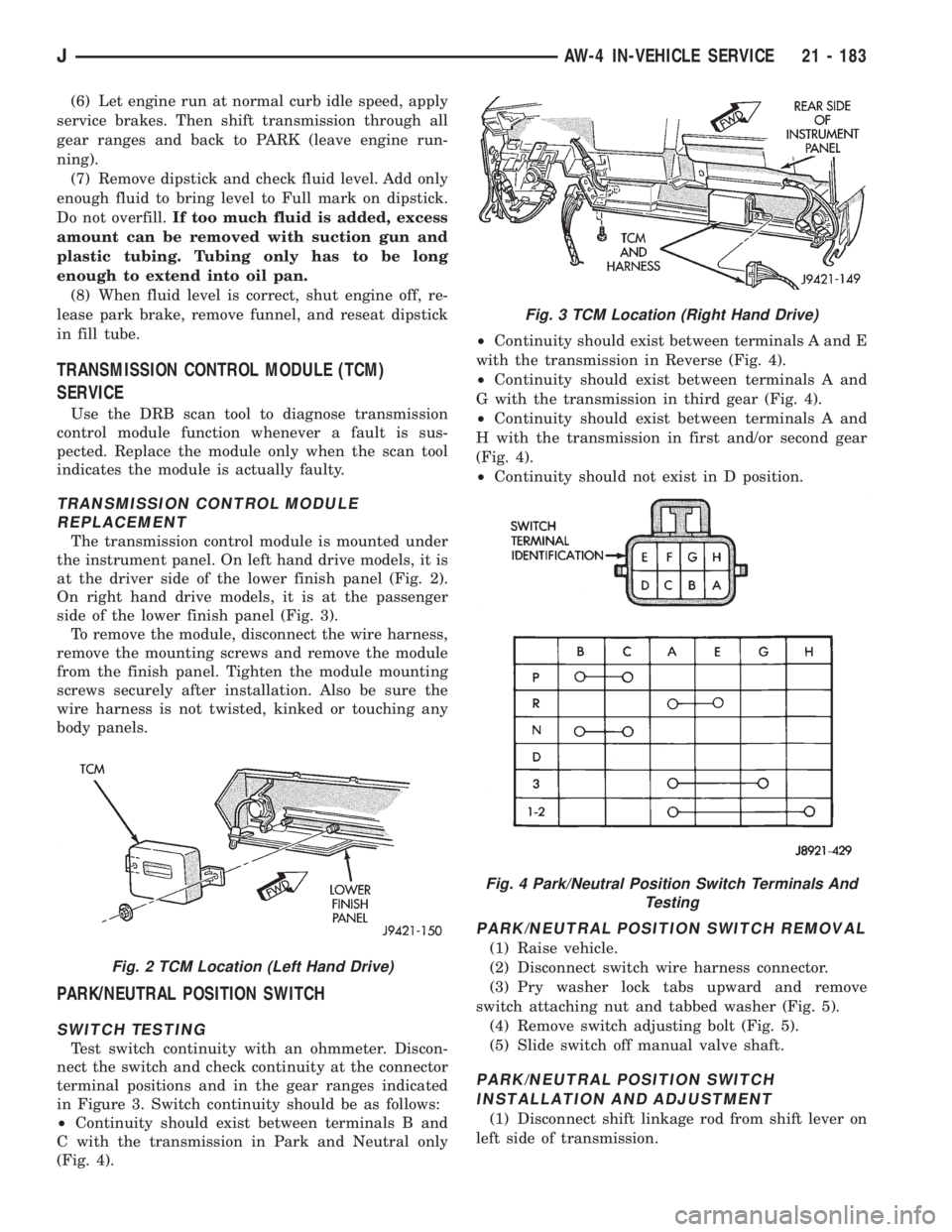
The transmission control module is mounted under
the instrument panel. On left hand drive models, it is
at the driver side of the lower finish panel (Fig. 2).
On right hand drive models, it is at the passenger
side of the lower finish panel (Fig. 3).
To remove the module, disconnect the wire harness,
remove the mounting screws and remove the module
from the finish panel. Tighten the module mounting
screws securely after installation. Also be sure the
wire harness is not twisted, kinked or touching any
body panels.
PARK/NEUTRAL POSITION SWITCH
SWITCH TESTING
Test switch continuity with an ohmmeter. Discon-
nect the switch and check continuity at the connector
terminal positions and in the gear ranges indicated
in Figure 3. Switch continuity should be as follows:
²Continuity should exist between terminals B and
C with the transmission in Park and Neutral only
(Fig. 4).²Continuity should exist between terminals A and E
with the transmission in Reverse (Fig. 4).
²Continuity should exist between terminals A and
G with the transmission in third gear (Fig. 4).
²Continuity should exist between terminals A and
H with the transmission in first and/or second gear
(Fig. 4).
²Continuity should not exist in D position.
PARK/NEUTRAL POSITION SWITCH REMOVAL
(1) Raise vehicle.
(2) Disconnect switch wire harness connector.
(3) Pry washer lock tabs upward and remove
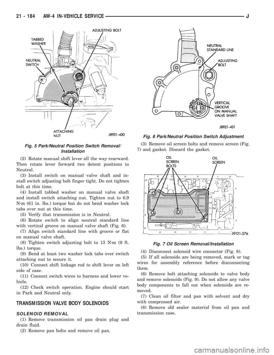
switch attaching nut and tabbed washer (Fig. 5).
(4) Remove switch adjusting bolt (Fig. 5).
(5) Slide switch off manual valve shaft.
PARK/NEUTRAL POSITION SWITCH
INSTALLATION AND ADJUSTMENT
(1) Disconnect shift linkage rod from shift lever on
left side of transmission.
Fig. 2 TCM Location (Left Hand Drive)
Fig. 3 TCM Location (Right Hand Drive)
Fig. 4 Park/Neutral Position Switch Terminals And
Testing
JAW-4 IN-VEHICLE SERVICE 21 - 183
Page 1746 of 2158
(2) Rotate manual shift lever all the way rearward.
Then rotate lever forward two detent positions to
Neutral.
(3) Install switch on manual valve shaft and in-
stall switch adjusting bolt finger tight. Do not tighten
bolt at this time.
(4) Install tabbed washer on manual valve shaft
and install switch attaching nut. Tighten nut to 6.9
Nzm (61 in. lbs.) torque but do not bend washer lock
tabs over nut at this time.
(5) Verify that transmission is in Neutral.
(6) Rotate switch to align neutral standard line
with vertical groove on manual valve shaft (Fig. 6).
(7) Align switch standard line with groove or flat
on manual valve shaft.
(8) Tighten switch adjusting bolt to 13 Nzm(9ft.
lbs.) torque.
(9) Bend at least two washer lock tabs over switch
attaching nut to secure it.
(10) Connect shift linkage rod to shift lever on left
side of case.
(11) Connect switch wires to harness and lower ve-
hicle.
(12) Check switch operation. Engine should start
in Park and Neutral only.
TRANSMISSION VALVE BODY SOLENOIDS
SOLENOID REMOVAL
(1) Remove transmission oil pan drain plug and
drain fluid.
(2) Remove pan bolts and remove oil pan.(3) Remove oil screen bolts and remove screen (Fig.
7) and gasket. Discard the gasket.
(4) Disconnect solenoid wire connector (Fig. 8).
(5) If all solenoids are being removed, mark or tag
wires for assembly reference before disconnecting
them.
(6) Remove bolt attaching solenoids to valve body
and remove solenoids (Fig. 9). Do not allow any valve
body components to fall out when solenoids are re-
moved.
(7) Clean oil filter and pan with solvent and dry
with compressed air.
(8) Remove old sealer material from oil pan and
transmission case.
Fig. 5 Park/Neutral Position Switch Removal/
Installation
Fig. 6 Park/Neutral Position Switch Adjustment
Fig. 7 Oil Screen Removal/Installation
21 - 184 AW-4 IN-VEHICLE SERVICEJ
Page 1757 of 2158
SHIFT CABLE ADJUSTMENT
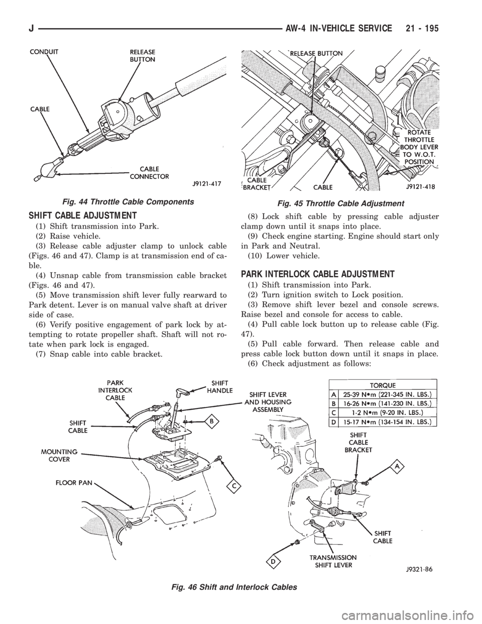
(1) Shift transmission into Park.
(2) Raise vehicle.
(3) Release cable adjuster clamp to unlock cable
(Figs. 46 and 47). Clamp is at transmission end of ca-
ble.
(4) Unsnap cable from transmission cable bracket
(Figs. 46 and 47).
(5) Move transmission shift lever fully rearward to
Park detent. Lever is on manual valve shaft at driver
side of case.
(6) Verify positive engagement of park lock by at-
tempting to rotate propeller shaft. Shaft will not ro-
tate when park lock is engaged.
(7) Snap cable into cable bracket.(8) Lock shift cable by pressing cable adjuster
clamp down until it snaps into place.
(9) Check engine starting. Engine should start only
in Park and Neutral.
(10) Lower vehicle.
PARK INTERLOCK CABLE ADJUSTMENT
(1) Shift transmission into Park.
(2) Turn ignition switch to Lock position.
(3) Remove shift lever bezel and console screws.
Raise bezel and console for access to cable.
(4) Pull cable lock button up to release cable (Fig.
47).
(5) Pull cable forward. Then release cable and
press cable lock button down until it snaps in place.
(6) Check adjustment as follows:
Fig. 45 Throttle Cable Adjustment
Fig. 46 Shift and Interlock Cables
Fig. 44 Throttle Cable Components
JAW-4 IN-VEHICLE SERVICE 21 - 195
Page 1759 of 2158
the front bumper and radiator support be removed
for access to the cooler lines and attaching bracket.
REVERSE FLUSHING MAIN AND AUXILIARY
COOLERS AND COOLER LINES
Reverse flushing the cooler and lines will prevent
sludge and particles from flowing back into the
transmission after repair. The flushing procedure ap-
plies to standard (in-radiator) coolers and auxiliary
coolers equally.
Pressure equipment is preferred for reverse flush-
ing. However, reverse flushing can be performed us-
ing hand operated equipment as described in the
following procedure.
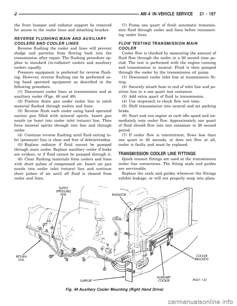
(1) Disconnect cooler lines at transmission and at
auxiliary cooler (Figs. 48 and 49).
(2) Position drain pan under cooler line to catch
material flushed through coolers and lines.
(3) Reverse flush each cooler using hand operated
suction gun filled with mineral spirits. Insert gun
nozzle (or hose) into cooler inlet (return) line. Then
force mineral spirits through into line and through
cooler.
(4) Continue reverse flushing until fluid exiting in-
let (pressure) line is clear and free of debris/residue.
(5) Replace radiator if fluid cannot be pumped
through main cooler. Replace auxiliary cooler if leaks
are evident, or if fluid cannot be pumped through it.
(6) Clear flushing materials from coolers and lines
with short pulses of compressed air. Insert air gun
nozzle into cooler inlet (return) line and continue
short pulses of air until all fluid is cleared from
cooler and lines.(7) Pump one quart of fresh automatic transmis-
sion fluid through cooler and lines before reconnect-
ing cooler lines.
FLOW TESTING TRANSMISSION MAIN
COOLER
Cooler flow is checked by measuring the amount of
fluid flow through the cooler in a 20 second time pe-
riod. The test is performed with the engine running
and transmission in neutral. Fluid is then pumped
through the cooler by the transmission oil pump.
(1) Disconnect cooler inlet line at transmission fit-
ting.
(2) Securely attach hose to end of inlet line and po-
sition line in a one quart test container.
(3) Add extra quart of fluid to transmission.
(4) Use stopwatch to check flow test time.
(5) Shift transmission into neutral and set parking
brake.
(6) Start and run engine at curb idle speed and im-
mediately note cooler flow. Approximately one quart
of fluid should flow into test container in 20 second
period.
(7) If cooler flow is intermittent, flows less than
one quart in 20 seconds, or does not flow at all,
cooler is faulty and must be replaced.
TRANSMISSION COOLER LINE FITTINGS
Quick connect fittings are used at the transmission
cooler line connections. The fitting seals and guides
are serviceable.
Replace the seals and guides whenever the fittings
exhibit leakage, or will not properly snap into place.
Fig. 49 Auxiliary Cooler Mounting (Right Hand Drive)
JAW-4 IN-VEHICLE SERVICE 21 - 197
Page 1761 of 2158
TORQUE CONVERTER STATOR CLUTCH
INSPECTION
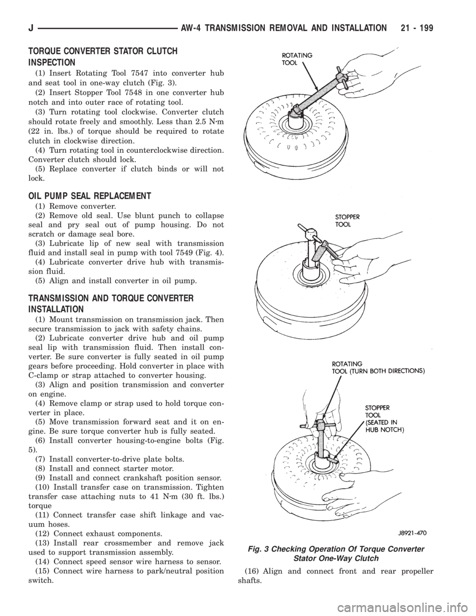
(1) Insert Rotating Tool 7547 into converter hub
and seat tool in one-way clutch (Fig. 3).
(2) Insert Stopper Tool 7548 in one converter hub
notch and into outer race of rotating tool.
(3) Turn rotating tool clockwise. Converter clutch
should rotate freely and smoothly. Less than 2.5 Nzm
(22 in. lbs.) of torque should be required to rotate
clutch in clockwise direction.
(4) Turn rotating tool in counterclockwise direction.
Converter clutch should lock.
(5) Replace converter if clutch binds or will not
lock.
OIL PUMP SEAL REPLACEMENT
(1) Remove converter.
(2) Remove old seal. Use blunt punch to collapse
seal and pry seal out of pump housing. Do not
scratch or damage seal bore.
(3) Lubricate lip of new seal with transmission
fluid and install seal in pump with tool 7549 (Fig. 4).
(4) Lubricate converter drive hub with transmis-
sion fluid.
(5) Align and install converter in oil pump.
TRANSMISSION AND TORQUE CONVERTER
INSTALLATION
(1) Mount transmission on transmission jack. Then
secure transmission to jack with safety chains.
(2) Lubricate converter drive hub and oil pump
seal lip with transmission fluid. Then install con-
verter. Be sure converter is fully seated in oil pump
gears before proceeding. Hold converter in place with
C-clamp or strap attached to converter housing.
(3) Align and position transmission and converter
on engine.
(4) Remove clamp or strap used to hold torque con-
verter in place.
(5) Move transmission forward seat and it on en-
gine. Be sure torque converter hub is fully seated.
(6) Install converter housing-to-engine bolts (Fig.
5).
(7) Install converter-to-drive plate bolts.
(8) Install and connect starter motor.
(9) Install and connect crankshaft position sensor.
(10) Install transfer case on transmission. Tighten
transfer case attaching nuts to 41 Nzm (30 ft. lbs.)
torque
(11) Connect transfer case shift linkage and vac-
uum hoses.
(12) Connect exhaust components.
(13) Install rear crossmember and remove jack
used to support transmission assembly.
(14) Connect speed sensor wire harness to sensor.
(15) Connect wire harness to park/neutral position
switch.(16) Align and connect front and rear propeller
shafts.
Fig. 3 Checking Operation Of Torque Converter
Stator One-Way Clutch
JAW-4 TRANSMISSION REMOVAL AND INSTALLATION 21 - 199
Page 2091 of 2158
REFRIGERANT SERVICE AND PERFORMANCE TEST
INDEX
page page
Air Conditioning Performance Tests............ 12
Charging Refrigerant System................. 11
Evacuating Refrigerant System............... 11Leak Testing Refrigerant.................... 11
Recovering Refrigerant System............... 11
Refrigerant Oil........................... 12
LEAK TESTING REFRIGERANT
REVIEW WARNINGS AND CAUTIONS IN
THIS GROUP BEFORE LEAK TESTING.
If A/C system is not cooling properly, determine if
system is fully charged. Refer to Refrigerant System
Diagnosis Chart. If the system is empty evacuate the
A/C system and charge system with 0.283 kPa (0.6
lbs. or 10 oz.) R-134a refrigerant. Refer to Charging
Refrigerant System for instructions. To detect a leak
in the system, perform the following procedures.
(1) Position the vehicle in a wind free work area.
This will aid in detecting small leaks.
(2) Bring A/C system up to operating temperature
and pressure. This is done by allowing the engine to
run with the A/C on for 5 to 7 minutes.
(3) Open hood 5 minutes prior to leak test. This
will dissipate any accumulated refrigerant in the en-
gine compartment.
(4) With the engine not running, use an R-134a
Electronic Leak Detector and search for leaks. Move
probe slowly along the bottom side of lines and fit-
tings, because R-134a is heavier than air. Fittings,
lines, or components that appear to be oily usually
indicates a refrigerant leak.
(5) To inspect the evaporator core for leaks. Set the
blower at low speed and the selector in PANEL and
RECIRC mode check for leaks at CENTER panel out-
lets.
RECOVERING REFRIGERANT SYSTEM
REVIEW WARNINGS AND CAUTIONS IN
GENERAL INFORMATION SECTION OF THIS
GROUP BEFORE DISCHARGING SYSTEM.
R-134a refrigerant is a hydrofluorocarbon (HFC)
that does not contain chlorine. R-134a refrigerant Re-
covery/Recycling Station that meets SAE standard
J2210 must be used to recover the refrigerant. Refer
to the operating instructions provided with the equip-
ment for proper operation.
EVACUATING REFRIGERANT SYSTEM
REVIEW WARNINGS AND CAUTIONS IN
GENERAL INFORMATION SECTION OF THIS
GROUP BEFORE EVACUATING SYSTEM.
If the A/C system has been open to the atmosphere,
it must be evacuated before the system can be
charged. Moisture and air mixed with refrigerant will
raise the compressor head pressure above acceptable
operating levels. This will reduce the performance of
the air conditioner and damage the compressor. Mois-
ture will boil at near room temperature when ex-
posed to vacuum. To evacuate the refrigerant system
use following procedure:
(1) Connect a suitable charging station and mani-
fold gauge set to the vehicle.
(2) Open the low and high side valves and start
vacuum pump. When suction gauge reads 88 kPa (26
in. Hg) vacuum or greater, close all valves and turn
off vacuum pump. If system fails to reach specified
vacuum, the system has a leak that must be cor-
rected. If system maintains the specified vacuum for
30 minutes, start the vacuum pump. Then open the
suction and discharge valves and evacuate an addi-
tional 10 minutes.
(3) Close all valves. Turn off and disconnect the
vacuum pump.
The system is now ready to be charged with refrig-
erant.
CHARGING REFRIGERANT SYSTEM
REVIEW WARNINGS AND CAUTIONS IN
GENERAL INFORMATION SECTION OF THIS
GROUP BEFORE CHARGING SYSTEM.
After the system has been tested for leaks and
evacuated, a refrigerant charge can be injected into
the system. Refer to refrigerant capacities for proper
amount of refrigerant charge. Charge the system us-
ing a Recovery/Recycling/Charging Station approved
for R-134a refrigerant. Refer to the instructions pro-
vided with the equipment for proper operation.
REFRIGERANT CHARGE CAPACITY
The R-134a system charge capacity is 0.9 kPa (32
oz.) for XJ and YJ vehicles.
JHEATING AND AIR CONDITIONING 24 - 11