1995 JEEP YJ power steering
[x] Cancel search: power steeringPage 184 of 2158

BRAKELIGHT SWITCH REMOVAL
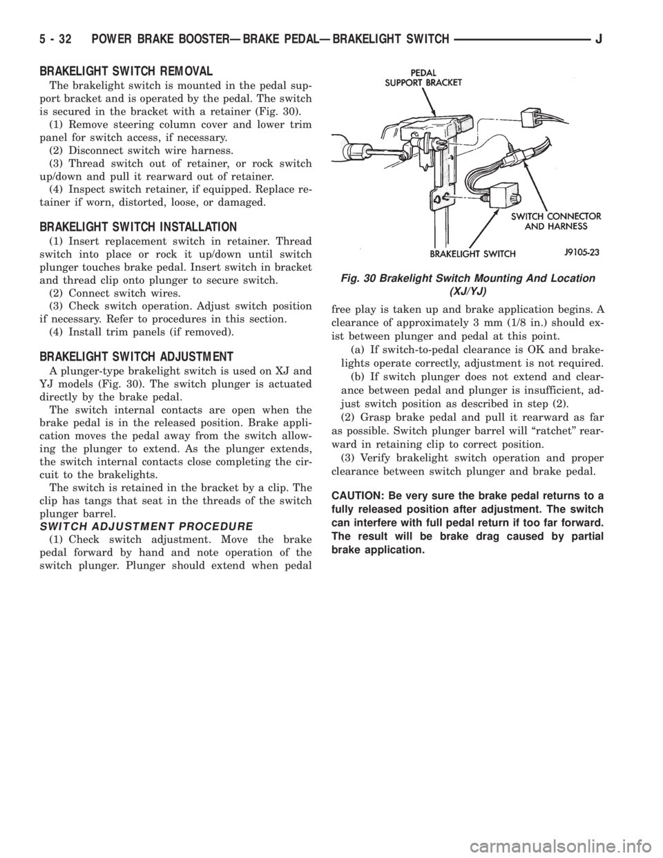
The brakelight switch is mounted in the pedal sup-
port bracket and is operated by the pedal. The switch
is secured in the bracket with a retainer (Fig. 30).
(1) Remove steering column cover and lower trim
panel for switch access, if necessary.
(2) Disconnect switch wire harness.
(3) Thread switch out of retainer, or rock switch
up/down and pull it rearward out of retainer.
(4) Inspect switch retainer, if equipped. Replace re-
tainer if worn, distorted, loose, or damaged.
BRAKELIGHT SWITCH INSTALLATION
(1) Insert replacement switch in retainer. Thread
switch into place or rock it up/down until switch
plunger touches brake pedal. Insert switch in bracket
and thread clip onto plunger to secure switch.
(2) Connect switch wires.
(3) Check switch operation. Adjust switch position
if necessary. Refer to procedures in this section.
(4) Install trim panels (if removed).
BRAKELIGHT SWITCH ADJUSTMENT
A plunger-type brakelight switch is used on XJ and
YJ models (Fig. 30). The switch plunger is actuated
directly by the brake pedal.
The switch internal contacts are open when the
brake pedal is in the released position. Brake appli-
cation moves the pedal away from the switch allow-
ing the plunger to extend. As the plunger extends,
the switch internal contacts close completing the cir-
cuit to the brakelights.
The switch is retained in the bracket by a clip. The
clip has tangs that seat in the threads of the switch
plunger barrel.
SWITCH ADJUSTMENT PROCEDURE
(1) Check switch adjustment. Move the brake
pedal forward by hand and note operation of the
switch plunger. Plunger should extend when pedalfree play is taken up and brake application begins. A
clearance of approximately 3 mm (1/8 in.) should ex-
ist between plunger and pedal at this point.
(a) If switch-to-pedal clearance is OK and brake-
lights operate correctly, adjustment is not required.
(b) If switch plunger does not extend and clear-
ance between pedal and plunger is insufficient, ad-
just switch position as described in step (2).
(2) Grasp brake pedal and pull it rearward as far
as possible. Switch plunger barrel will ``ratchet'' rear-
ward in retaining clip to correct position.
(3) Verify brakelight switch operation and proper
clearance between switch plunger and brake pedal.
CAUTION: Be very sure the brake pedal returns to a
fully released position after adjustment. The switch
can interfere with full pedal return if too far forward.
The result will be brake drag caused by partial
brake application.
Fig. 30 Brakelight Switch Mounting And Location
(XJ/YJ)
5 - 32 POWER BRAKE BOOSTERÐBRAKE PEDALÐBRAKELIGHT SWITCHJ
Page 185 of 2158

ABS OPERATION AND SERVICE
INDEX
page page
ABS Component Serviceability............... 37
ABS Diagnostic Connector.................. 35
ABS Operation in Antilock Braking Mode........ 36
ABS Operation in Normal Braking Mode........ 35
ABS System Power-Up and Initialization........ 35
Acceleration Switch........................ 35
Acceleration Switch Installation............... 39
Acceleration Switch Operation................ 37
Acceleration Switch Removal................ 39
Combination Valve........................ 34
ECU Installation (XJ Models)................. 40
ECU Operation........................... 37
ECU Removal (XJ Models).................. 40
ECU Removal/Installation (YJ Models).......... 41
Electronic Control Unit (ECU)................ 34
Front Wheel Sensor Installation............... 38
Front Wheel Sensor Removal................ 38HCU Installation (XJ)....................... 43
HCU Installation (YJ)....................... 44
HCU Operation........................... 36
HCU Removal (XJ)........................ 41
HCU Removal (YJ)........................ 44
Hydraulic Control Unit (HCU)................. 33
Ignition Switch........................... 35
Master Cylinder/Power Brake Booster.......... 34
Rear Wheel Sensor Installation and Adjustment . . . 38
Rear Wheel Sensor Removal................ 38
Speed Sensor Air Gap..................... 37
System Description........................ 33
System Relays........................... 35
System Warning Light...................... 35
Wheel Speed Sensor Operation.............. 37
Wheel Speed Sensors..................... 34
SYSTEM DESCRIPTION
The Jeep antilock brake system (ABS) is an elec-
tronically operated, all wheel brake control system.
The system is designed to prevent wheel lockup
and maintain steering control during periods of high
wheel slip when braking. Preventing lockup is accom-
plished by modulating fluid pressure to the wheel
brake units.
The hydraulic system is a three channel design.
The front wheel brakes are controlled individually
and the rear wheel brakes in tandem (Fig. 1). The
ABS electrical system is separate from other electri-
cal circuits in the vehicle. A specially programmed
electronic control unit (ECU) operates the system
components.
ABS system major components include:
²hydraulic control unit (HCU)
²electronic control unit (ECU)
²wheel speed sensors and axle shaft tone rings
²acceleration switch
²main relay and pump motor relay
²ABS warning light
²pump motor sensor
HYDRAULIC CONTROL UNIT (HCU)
The hydraulic control unit (HCU) consists of a
valve body, pump body, accumulators, pump motor,
and wire harnesses (Fig. 2).
The pump, motor, and accumulators are combined
into an assembly attached to the valve body. The ac-
cumulators store the extra fluid released to the sys-
tem for ABS mode operation. The pump provides the
fluid volume needed and is operated by a DC type
motor. The motor is controlled by the ECU.The valve body contains the solenoid valves. The
valves modulate brake pressure during antilock brak-
ing and are controlled by the ECU.
The HCU provides three channel pressure control
to the front and rear brakes. One channel controls
the rear wheel brakes in tandem. The two remaining
channels control the front wheel brakes individually.
During antilock braking, the solenoid valves are
opened and closed as needed. The valves are not static.
They are cycled rapidly and continuously to modulate
pressure and control wheel slip and deceleration.
Fig. 1 Jeep ABS System
JABS OPERATION AND SERVICE 5 - 33
Page 186 of 2158

MASTER CYLINDER/POWER BRAKE BOOSTER
A 25 mm bore master cylinder and 205 mm (8.07
in.) dual diaphragm power brake booster are used for
all ABS applications (Fig. 2).
The master cylinder has a removable plastic reser-
voir which is the only serviceable component. The
cylinder body and pistons are not repairable and are
serviced as an assembly. The check valve and grom-
met are the only serviceable parts on the booster.
The booster itself is only serviced as an assembly.
COMBINATION VALVE
A combination valve is used with the ABS system
(Fig. 2). The valve contains a front/rear brake pres-
sure differential switch and rear brake proportioning
valve. The combination valve is connected between
the master cylinder and HCU.
The pressure differential switch is connected to the
red brake warning light. The switch is actuated by
movement of the switch valve. The switch monitors
fluid pressure in the separate front/rear brake hy-
draulic circuits.
A decrease or loss of fluid pressure in either hy-
draulic circuit will cause the switch valve to shuttle
forward or rearward in response to the pressure dif-
ferential. Movement of the switch valve will push the
switch plunger upward. This closes the switch inter-
nal contacts completing the electrical circuit to the
red warning light. The switch valve remains in an
actuated position until the fault is repaired.
The rear proportioning valve is used to balance front-
rear brake action.
ELECTRONIC CONTROL UNIT (ECU)
A separate electronic control unit (ECU) operates
the ABS system (Fig. 3). The ECU is separate from
other vehicle electrical circuits. ECU voltage source
is through the ignition switch in the Run position.The ECU is located under the instrument panel in
the passenger compartment. On YJ models, it is just
above the heater plenum in line with the glove box.
In left hand drive XJ models, it at the right side of
the steering column. In right hand drive models, it is
near the cowl panel
The ECU contains dual microprocessors. A logic
block in each microprocessor receives identical sensor
signals. These signals are processed and compared si-
multaneously.
The ECU contains a self check program that illu-
minates the ABS warning light when a system fault
is detected. Faults are stored in a diagnostic program
memory and are accessible with the DRB scan tool.
ABS faults remain in memory until cleared, or un-
til after the vehicle is started approximately 50
times. Stored faults arenoterased if the battery is
disconnected.
WHEEL SPEED SENSORS
A speed sensor is used at each wheel. The sensors
convert wheel speed into an electrical signal. This
signal is transmitted to the antilock ECU.
A gear type tone ring serves as the trigger mecha-
nism for each sensor. The tone rings are mounted at
the outboard ends of the front and rear axle shafts.
Different sensors are used at the front and rear
wheels (Fig. 4). The front/rear sensors have the same
electrical values but are not interchangeable.
Fig. 2 ABS Master Cylinder-Booster-Combination
Valve-HCU
Fig. 3 Antilock ECU
5 - 34 ABS OPERATION AND SERVICEJ
Page 187 of 2158

ABS DIAGNOSTIC CONNECTOR
The ABS diagnostic connector is inside the vehicle.
The connector is the access point for the DRB scan
tool.
On XJ models, the connector is located under the
instrument panel to the right of the steering column.
On some models, the connecter may be tucked under
the carpeting on the transmission tunnel. The con-
necter is a black, 6-way type.
On YJ models, the connector is under the instru-
ment panel by the the driver side kick panel. The
connecter is a black, 6 or 8-way type.
The DRB scan tool kit contains adapter cords for
both types of connecter. Use the appropriate cord for
test hookup.
ACCELERATION SWITCH
An acceleration switch (Fig. 5), provides an addi-
tional vehicle deceleration reference during 4-wheel
drive operation. The switch is monitored by the an-
tilock ECU at all times. The switch reference signal
is utilized by the ECU when all wheels are deceler-
ating at the same speed.
SYSTEM RELAYS
The ABS system has two relays, which are the
main and motor pump relays. The motor pump relay
is used for the motor pump only. The main relay is
used for the solenoid valves and ECU. The main re-
lay is connected to the ECU at the power control re-
lay terminal. The pump motor relay starts/stops the
pump motor when signaled by the ECU.
IGNITION SWITCH
The antilock ECU and warning light are in standby
mode with the ignition switch in Off or Accessory po-
sition. No operating voltage is supplied to the system
components.A 12 volt power feed is supplied to the ECU and
warning light when the ignition switch is in the Run
position.
SYSTEM WARNING LIGHT
The amber ABS warning light is in circuit with the
ECU and operates independently of the red brake
warning light.
The ABS light indicates antilock system condition.
The light illuminates (flashes) at start-up for the self
check. The light goes out when the self check pro-
gram determines system operation is normal.
ABS SYSTEM POWER-UP AND INITIALIZATION
battery voltage is supplied to the ECU ignition ter-
minal when the ignition switch is turned to Run po-
sition. The ECU performs a system initialization
procedure at this point. Initialization consists of a
static and dynamic self check of system electrical
components.
The static check occurs after the ignition switch is
turned to Run position. The dynamic check occurs
when vehicle road speed reaches approximately 10
kph (6 mph). During the dynamic check, the ECU
briefly cycles the pump and solenoids to verify oper-
ation.
If an ABS component exhibits a fault during initial-
ization, the ECU illuminates the amber warning
light and registers a fault code in the microprocessor
memory.
ABS OPERATION IN NORMAL BRAKING MODE
The ECU monitors wheel speed sensor inputs con-
tinuously while the vehicle is in motion. However,
the ECU will not activate any ABS components as
long as sensor inputs and the acceleration switch in-
dicate normal braking.
Fig. 4 Wheel Speed SensorsFig. 5 Acceleration Switch
JABS OPERATION AND SERVICE 5 - 35
Page 188 of 2158

During normal braking, the master cylinder, power
booster and wheel brake units all function as they
would in a vehicle without ABS. The HCU compo-
nents are not activated.
ABS OPERATION IN ANTILOCK BRAKING MODE
The purpose of the antilock system is to prevent
wheel lockup during periods of high wheel slip. Pre-
venting lockup helps maintain vehicle braking action
and steering control.
The antilock ECU activates the system whenever
sensor signals indicate periods of high wheel slip.
High wheel slip can be described as the point where
wheel rotation begins approaching zero (or lockup)
during braking. Periods of high wheel slip may occur
when brake stops involve high pedal pressure and
rate of deceleration.
The antilock system prevents lockup during high
slip conditions by modulating fluid apply pressure to
the wheel brake units.
Brake fluid apply pressure is modulated according
to wheel speed, degree of slip and rate of decelera-
tion. A sensor at each wheel converts wheel speed
into electrical signals. These signals are transmitted
to the ECU for processing and determination of
wheel slip and deceleration rate.
The ABS system has three fluid pressure control
channels. The front brakes are controlled separately
and the rear brakes in tandem (Fig. 1). A speed sen-
sor input signal indicating a high slip condition acti-
vates the ECU antilock program.
Two solenoid valves are used in each antilock con-
trol channel. The valves are all located within the
HCU valve body and work in pairs to either increase,
hold, or decrease apply pressure as needed in the in-
dividual control channels.
The solenoid valves are not static during antilock
braking. They are cycled continuously to modulate
pressure. Solenoid cycle time in antilock mode can be
measured in milliseconds.
HCU OPERATION
Normal Braking
During normal braking, the HCU solenoid valves
and pump are not activated. The master cylinder and
power booster operate the same as a vehicle without
an ABS brake system.
Antilock Pressure Modulation
Solenoid valve pressure modulation occurs in three
stages which are: pressure increase, pressure hold,
and pressure decrease. The valves are all contained
in the valve body portion of the HCU.
Pressure Decrease
The outlet valve is opened and the inlet valve is
closed during the pressure decrease cycle (Fig. 6).A pressure decrease cycle is initiated when speed
sensor signals indicate high wheel slip at one or
more wheels. At this point, the ECU opens the outlet
valve, which also opens the return circuit to the ac-
cumulators. Fluid pressure is allowed to bleed off (de-
crease) as needed to prevent wheel lock.
Once the period of high wheel slip has ended, the
ECU closes the outlet valve and begins a pressure in-
crease or hold cycle as needed.
Pressure Hold
Both solenoid valves are closed in the pressure hold
cycle (Fig. 7). Fluid apply pressure in the control
channel is maintained at a constant rate. The ECU
maintains the hold cycle until sensor inputs indicate
a pressure change is necessary.
Pressure Increase
The inlet valve is open and the outlet valve is
closed during the pressure increase cycle (Fig. 8). The
pressure increase cycle is used to counteract unequal
wheel speeds. This cycle controls re-application of
fluid apply pressure due to changing road surfaces or
wheel speed.
Fig. 6 Pressure Decrease Cycle
5 - 36 ABS OPERATION AND SERVICEJ
Page 254 of 2158

The engine accessory drive belt must be removed
prior to removing the fan (if installed at pump) or
fan pulley.
(4) Remove engine drive belt as follows:
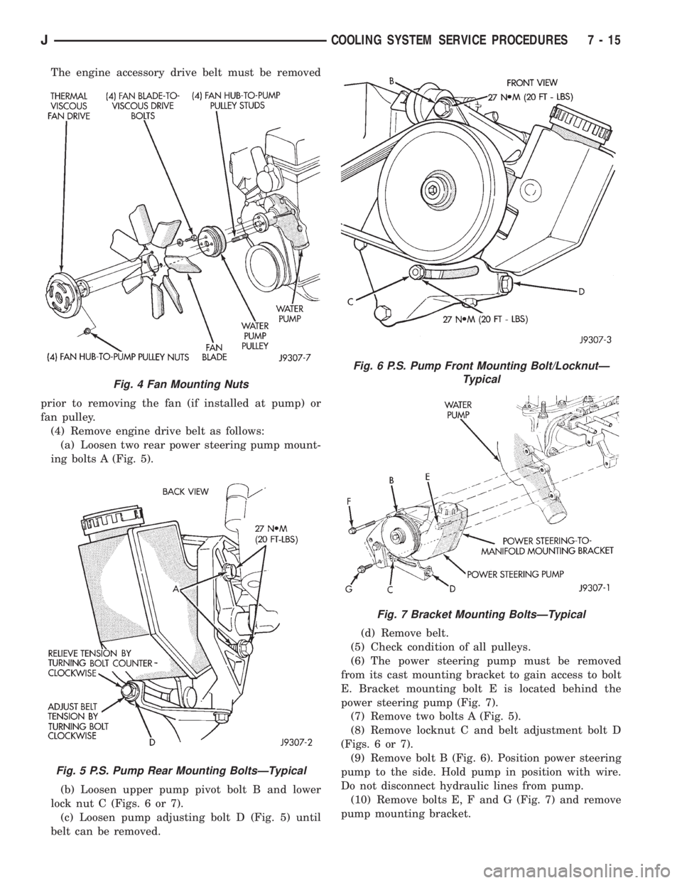
(a) Loosen two rear power steering pump mount-
ing bolts A (Fig. 5).
(b) Loosen upper pump pivot bolt B and lower
lock nut C (Figs. 6 or 7).
(c) Loosen pump adjusting bolt D (Fig. 5) until
belt can be removed.(d) Remove belt.
(5) Check condition of all pulleys.
(6) The power steering pump must be removed
from its cast mounting bracket to gain access to bolt
E. Bracket mounting bolt E is located behind the
power steering pump (Fig. 7).
(7) Remove two bolts A (Fig. 5).
(8) Remove locknut C and belt adjustment bolt D
(Figs. 6 or 7).
(9) Remove bolt B (Fig. 6). Position power steering
pump to the side. Hold pump in position with wire.
Do not disconnect hydraulic lines from pump.
(10) Remove bolts E, F and G (Fig. 7) and remove
pump mounting bracket.
Fig. 4 Fan Mounting Nuts
Fig. 5 P.S. Pump Rear Mounting BoltsÐTypical
Fig. 6 P.S. Pump Front Mounting Bolt/LocknutÐ
Typical
Fig. 7 Bracket Mounting BoltsÐTypical
JCOOLING SYSTEM SERVICE PROCEDURES 7 - 15
Page 256 of 2158

INSTALLATIONÐALL MODELS
(1) If pump is being replaced, install the heater
hose fitting to the pump. Use a sealant on the fitting
such as MoparŸ Thread Sealant With Teflon. Refer
to the directions on the package.
(2) Clean the gasket mating surfaces. If the origi-
nal pump is used, remove any deposits or other for-
eign material. Inspect the cylinder block and water
pump mating surfaces for erosion or damage from
cavitation.
(3) Install the gasket and water pump. The silicone
bead on the gasket should be facing the water pump.
Also, the gasket is installed dry. Tighten mounting
bolts to 30 Nzm (22 ft. lbs.) torque. Rotate the shaft
by hand to be sure it turns freely.
(4) Connect the radiator and heater hoses to the
water pump.
(5) Position water pump pulley to water pump hub.
(6) If equipped with a water pump mounted fan,
install fan and four nuts to water pump hub. If not
equipped with a water pump mounted fan, install
four pump hub bolts. Tighten bolts (or nuts) to 27
Nzm (20 ft. lbs.) torque.
(7) Position power steering pump bracket to en-
gine. Install bolts E, F and G (Fig. 7). Tighten bolts F
andGto38Nzm (28 ft. lbs.) torque. Tighten bolt E to
27 Nzm (20 ft. lbs.) torque.
(8) Position power steering pump to mounting
bracket. Install pivot bolt B (Fig. 6) finger tight. In-
stall locknut C and adjustment bolt D (Figs. 6 or 7)
finger tight.
(9) Install two adjustment bolts A (Fig. 6) finger
tight.
(10) Install idler pulley.
CAUTION: When installing the serpentine engine
accessory drive belt, the belt MUST be routed cor-
rectly. If not, the engine may overheat due to the
water pump rotating in the wrong direction. Refer to
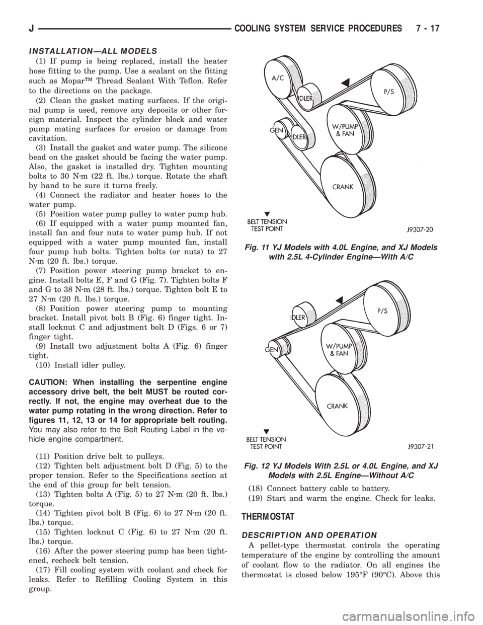
figures 11, 12, 13 or 14 for appropriate belt routing.
You may also refer to the Belt Routing Label in the ve-
hicle engine compartment.
(11) Position drive belt to pulleys.
(12) Tighten belt adjustment bolt D (Fig. 5) to the
proper tension. Refer to the Specifications section at
the end of this group for belt tension.
(13) Tighten bolts A (Fig. 5) to 27 Nzm (20 ft. lbs.)
torque.
(14) Tighten pivot bolt B (Fig. 6) to 27 Nzm (20 ft.
lbs.) torque.
(15) Tighten locknut C (Fig. 6) to 27 Nzm (20 ft.
lbs.) torque.
(16) After the power steering pump has been tight-
ened, recheck belt tension.
(17) Fill cooling system with coolant and check for
leaks. Refer to Refilling Cooling System in this
group.(18) Connect battery cable to battery.
(19) Start and warm the engine. Check for leaks.
THERMOSTAT
DESCRIPTION AND OPERATION
A pellet-type thermostat controls the operating
temperature of the engine by controlling the amount
of coolant flow to the radiator. On all engines the
thermostat is closed below 195ÉF (90ÉC). Above this
Fig. 11 YJ Models with 4.0L Engine, and XJ Models
with 2.5L 4-Cylinder EngineÐWith A/C
Fig. 12 YJ Models With 2.5L or 4.0L Engine, and XJ
Models with 2.5L EngineÐWithout A/C
JCOOLING SYSTEM SERVICE PROCEDURES 7 - 17
Page 270 of 2158

WAYS WEAR SAFETY GLASSES WHEN SERVICING
CONSTANT TENSION CLAMPS.
CAUTION: A number or letter is stamped into the
tongue of constant tension clamps (Fig. 28). If re-
placement is necessary, use only an original equip-
ment clamp with matching number or letter.
REMOVAL
(1) Disconnect negative battery cable at battery.
(2) Observe the previousWARNINGS.Remove the
radiator cap.
(3) Position drain pan under draincock. Open radi-
ator draincock and drain radiator.
(4) Remove radiator upper and lower hose clamps
(Figs 27 and 28). Remove radiator hoses.
(5) Disconnect coolant reserve/overflow tank hose
from radiator.
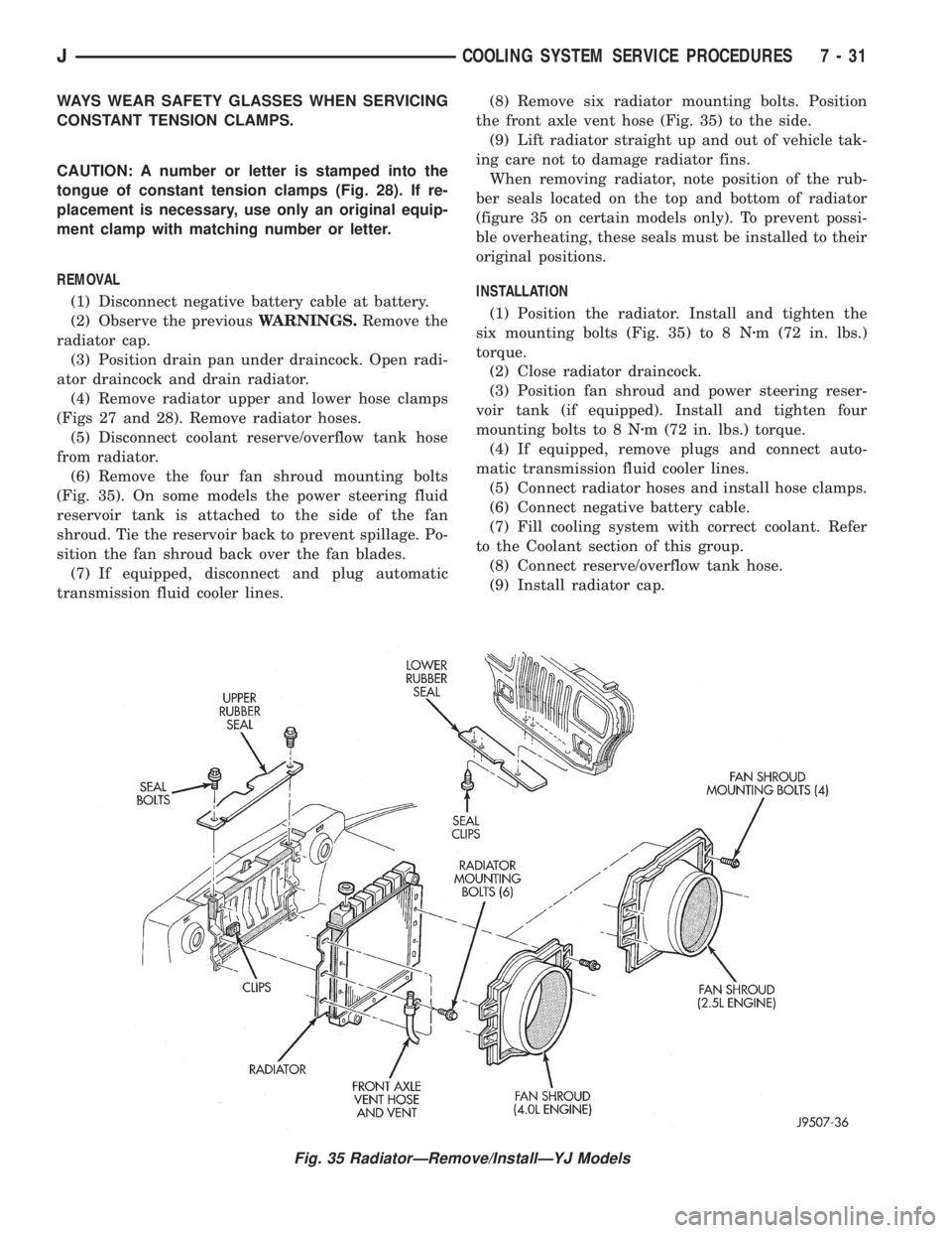
(6) Remove the four fan shroud mounting bolts
(Fig. 35). On some models the power steering fluid
reservoir tank is attached to the side of the fan
shroud. Tie the reservoir back to prevent spillage. Po-
sition the fan shroud back over the fan blades.
(7) If equipped, disconnect and plug automatic
transmission fluid cooler lines.(8) Remove six radiator mounting bolts. Position
the front axle vent hose (Fig. 35) to the side.
(9) Lift radiator straight up and out of vehicle tak-
ing care not to damage radiator fins.
When removing radiator, note position of the rub-
ber seals located on the top and bottom of radiator
(figure 35 on certain models only). To prevent possi-
ble overheating, these seals must be installed to their
original positions.
INSTALLATION
(1) Position the radiator. Install and tighten the
six mounting bolts (Fig. 35) to 8 Nzm (72 in. lbs.)
torque.
(2) Close radiator draincock.
(3) Position fan shroud and power steering reser-
voir tank (if equipped). Install and tighten four
mounting bolts to 8 Nzm (72 in. lbs.) torque.
(4) If equipped, remove plugs and connect auto-
matic transmission fluid cooler lines.
(5) Connect radiator hoses and install hose clamps.
(6) Connect negative battery cable.
(7) Fill cooling system with correct coolant. Refer
to the Coolant section of this group.
(8) Connect reserve/overflow tank hose.
(9) Install radiator cap.
Fig. 35 RadiatorÐRemove/InstallÐYJ Models
JCOOLING SYSTEM SERVICE PROCEDURES 7 - 31