1995 JEEP YJ fuel cap release
[x] Cancel search: fuel cap releasePage 1409 of 2158
OK and fuel pressure does not rise approximately
8-10 psi after disconnecting vacuum line, replace fuel
pressure regulator.
The fuel pressure regulator isnot adjustable.
(4) If fuel pressure exceeds 45 psi, check fuel re-
turn line/tube for kinks or obstructions.
If the previous tests checked good, fuel pump pres-
sure is correct. If pump pressure was low, proceed as
follows:
(5) Release fuel system pressure. Refer to the pre-
vious Fuel Pressure Release Procedure in this group.
(6) Disconnect the 5/16 inch fuel return line quick-
connect fitting at fuel rail. For procedures, refer to
Fuel Tubes/Lines/Hoses and Clamps. Also refer to
Quick-Connect Fittings. These can be found in the
Fuel Delivery System section of this group.
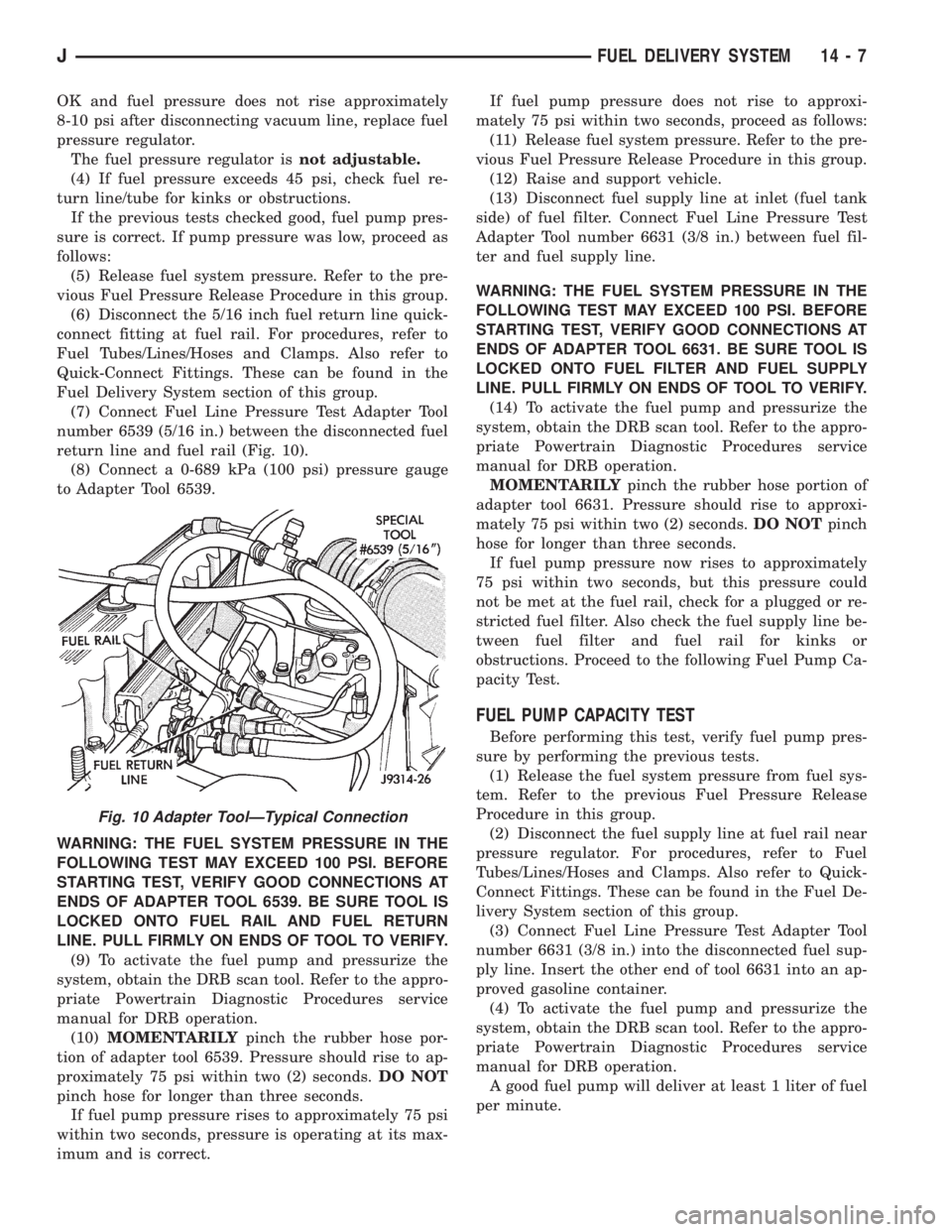
(7) Connect Fuel Line Pressure Test Adapter Tool
number 6539 (5/16 in.) between the disconnected fuel
return line and fuel rail (Fig. 10).
(8) Connect a 0-689 kPa (100 psi) pressure gauge
to Adapter Tool 6539.
WARNING: THE FUEL SYSTEM PRESSURE IN THE
FOLLOWING TEST MAY EXCEED 100 PSI. BEFORE
STARTING TEST, VERIFY GOOD CONNECTIONS AT
ENDS OF ADAPTER TOOL 6539. BE SURE TOOL IS
LOCKED ONTO FUEL RAIL AND FUEL RETURN
LINE. PULL FIRMLY ON ENDS OF TOOL TO VERIFY.
(9) To activate the fuel pump and pressurize the
system, obtain the DRB scan tool. Refer to the appro-
priate Powertrain Diagnostic Procedures service
manual for DRB operation.
(10)MOMENTARILYpinch the rubber hose por-
tion of adapter tool 6539. Pressure should rise to ap-
proximately 75 psi within two (2) seconds.DO NOT
pinch hose for longer than three seconds.
If fuel pump pressure rises to approximately 75 psi
within two seconds, pressure is operating at its max-
imum and is correct.If fuel pump pressure does not rise to approxi-
mately 75 psi within two seconds, proceed as follows:
(11) Release fuel system pressure. Refer to the pre-
vious Fuel Pressure Release Procedure in this group.
(12) Raise and support vehicle.
(13) Disconnect fuel supply line at inlet (fuel tank
side) of fuel filter. Connect Fuel Line Pressure Test
Adapter Tool number 6631 (3/8 in.) between fuel fil-
ter and fuel supply line.
WARNING: THE FUEL SYSTEM PRESSURE IN THE
FOLLOWING TEST MAY EXCEED 100 PSI. BEFORE
STARTING TEST, VERIFY GOOD CONNECTIONS AT
ENDS OF ADAPTER TOOL 6631. BE SURE TOOL IS
LOCKED ONTO FUEL FILTER AND FUEL SUPPLY
LINE. PULL FIRMLY ON ENDS OF TOOL TO VERIFY.
(14) To activate the fuel pump and pressurize the
system, obtain the DRB scan tool. Refer to the appro-
priate Powertrain Diagnostic Procedures service
manual for DRB operation.
MOMENTARILYpinch the rubber hose portion of
adapter tool 6631. Pressure should rise to approxi-
mately 75 psi within two (2) seconds.DO NOTpinch
hose for longer than three seconds.
If fuel pump pressure now rises to approximately
75 psi within two seconds, but this pressure could
not be met at the fuel rail, check for a plugged or re-
stricted fuel filter. Also check the fuel supply line be-
tween fuel filter and fuel rail for kinks or
obstructions. Proceed to the following Fuel Pump Ca-
pacity Test.
FUEL PUMP CAPACITY TEST
Before performing this test, verify fuel pump pres-
sure by performing the previous tests.
(1) Release the fuel system pressure from fuel sys-
tem. Refer to the previous Fuel Pressure Release
Procedure in this group.
(2) Disconnect the fuel supply line at fuel rail near
pressure regulator. For procedures, refer to Fuel
Tubes/Lines/Hoses and Clamps. Also refer to Quick-
Connect Fittings. These can be found in the Fuel De-
livery System section of this group.
(3) Connect Fuel Line Pressure Test Adapter Tool
number 6631 (3/8 in.) into the disconnected fuel sup-
ply line. Insert the other end of tool 6631 into an ap-
proved gasoline container.
(4) To activate the fuel pump and pressurize the
system, obtain the DRB scan tool. Refer to the appro-
priate Powertrain Diagnostic Procedures service
manual for DRB operation.
A good fuel pump will deliver at least 1 liter of fuel
per minute.
Fig. 10 Adapter ToolÐTypical Connection
JFUEL DELIVERY SYSTEM 14 - 7
Page 1410 of 2158
FUEL PRESSURE LEAK DOWN TEST
ENGINE OFF
Abnormally long periods of cranking to restart a
hot engine that has been shut down for a short pe-
riod of time may be caused by:
²Fuel pressure bleeding past the fuel pressure reg-
ulator.
²Fuel pressure bleeding past the check valve in the
outlet end of the fuel tank mounted fuel pump.
²Fuel pressure bleeding past a fuel injector(s)
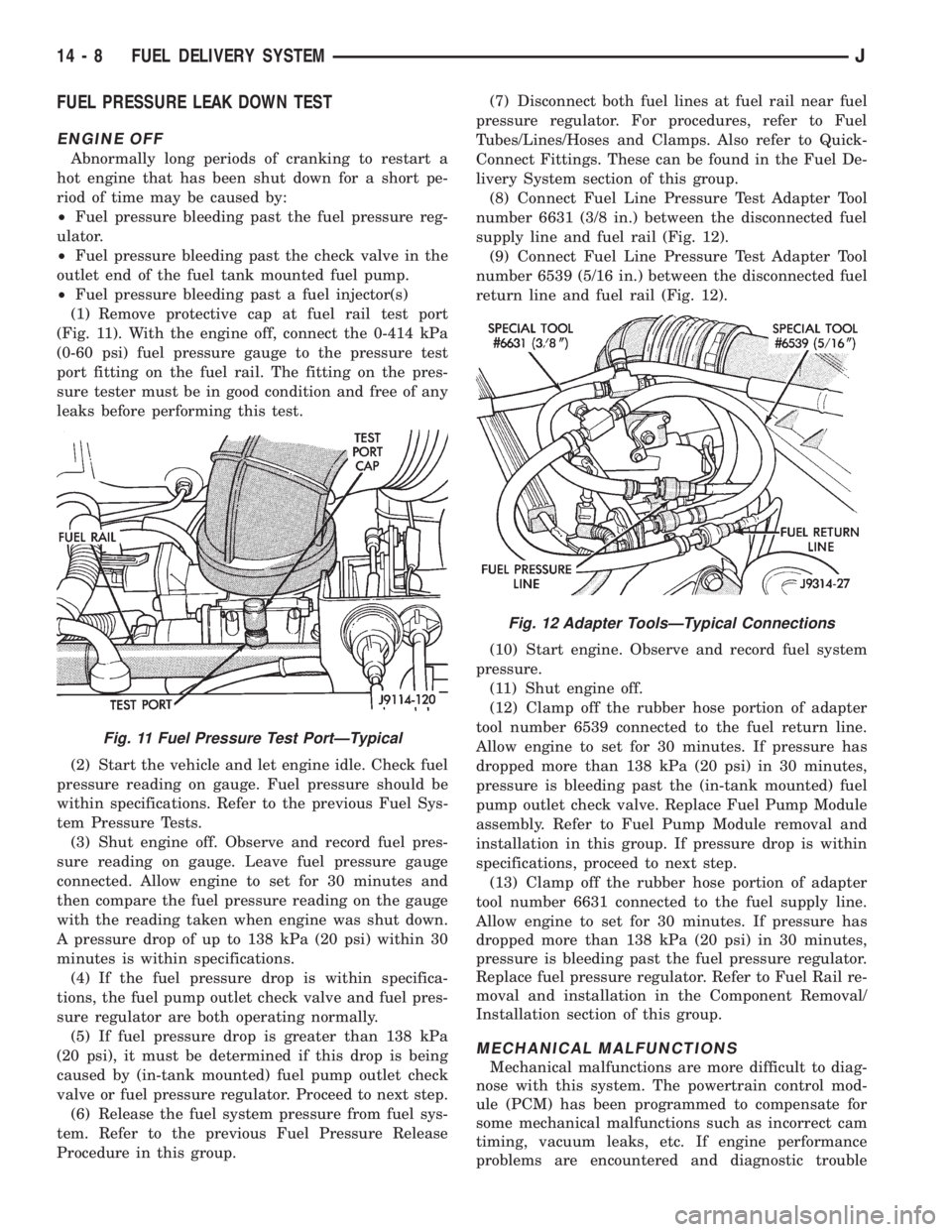
(1) Remove protective cap at fuel rail test port
(Fig. 11). With the engine off, connect the 0-414 kPa
(0-60 psi) fuel pressure gauge to the pressure test
port fitting on the fuel rail. The fitting on the pres-
sure tester must be in good condition and free of any
leaks before performing this test.
(2) Start the vehicle and let engine idle. Check fuel
pressure reading on gauge. Fuel pressure should be
within specifications. Refer to the previous Fuel Sys-
tem Pressure Tests.
(3) Shut engine off. Observe and record fuel pres-
sure reading on gauge. Leave fuel pressure gauge
connected. Allow engine to set for 30 minutes and
then compare the fuel pressure reading on the gauge
with the reading taken when engine was shut down.
A pressure drop of up to 138 kPa (20 psi) within 30
minutes is within specifications.
(4) If the fuel pressure drop is within specifica-
tions, the fuel pump outlet check valve and fuel pres-
sure regulator are both operating normally.
(5) If fuel pressure drop is greater than 138 kPa
(20 psi), it must be determined if this drop is being
caused by (in-tank mounted) fuel pump outlet check
valve or fuel pressure regulator. Proceed to next step.
(6) Release the fuel system pressure from fuel sys-
tem. Refer to the previous Fuel Pressure Release
Procedure in this group.(7) Disconnect both fuel lines at fuel rail near fuel
pressure regulator. For procedures, refer to Fuel
Tubes/Lines/Hoses and Clamps. Also refer to Quick-
Connect Fittings. These can be found in the Fuel De-
livery System section of this group.
(8) Connect Fuel Line Pressure Test Adapter Tool
number 6631 (3/8 in.) between the disconnected fuel
supply line and fuel rail (Fig. 12).
(9) Connect Fuel Line Pressure Test Adapter Tool
number 6539 (5/16 in.) between the disconnected fuel
return line and fuel rail (Fig. 12).
(10) Start engine. Observe and record fuel system
pressure.
(11) Shut engine off.
(12) Clamp off the rubber hose portion of adapter
tool number 6539 connected to the fuel return line.
Allow engine to set for 30 minutes. If pressure has
dropped more than 138 kPa (20 psi) in 30 minutes,
pressure is bleeding past the (in-tank mounted) fuel
pump outlet check valve. Replace Fuel Pump Module
assembly. Refer to Fuel Pump Module removal and
installation in this group. If pressure drop is within
specifications, proceed to next step.
(13) Clamp off the rubber hose portion of adapter
tool number 6631 connected to the fuel supply line.
Allow engine to set for 30 minutes. If pressure has
dropped more than 138 kPa (20 psi) in 30 minutes,
pressure is bleeding past the fuel pressure regulator.
Replace fuel pressure regulator. Refer to Fuel Rail re-
moval and installation in the Component Removal/
Installation section of this group.
MECHANICAL MALFUNCTIONS
Mechanical malfunctions are more difficult to diag-
nose with this system. The powertrain control mod-
ule (PCM) has been programmed to compensate for
some mechanical malfunctions such as incorrect cam
timing, vacuum leaks, etc. If engine performance
problems are encountered and diagnostic trouble
Fig. 11 Fuel Pressure Test PortÐTypical
Fig. 12 Adapter ToolsÐTypical Connections
14 - 8 FUEL DELIVERY SYSTEMJ
Page 1411 of 2158
codes are not displayed, the problem may be mechan-
ical rather than electronic.
FUEL FILTER
The fuel filter protects the fuel injectors and fuel
pressure regulator from dirt, water and other foreign
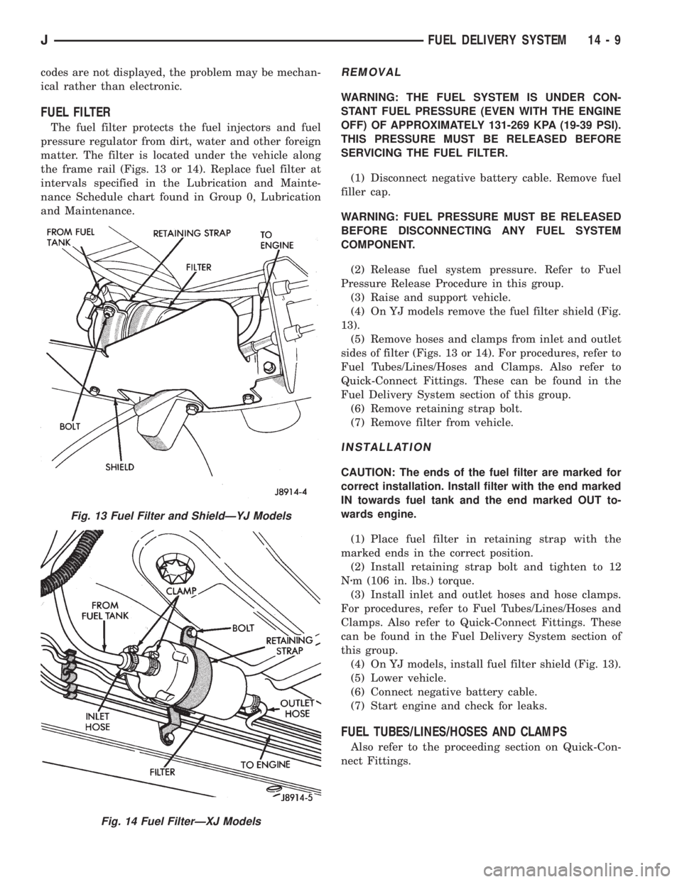
matter. The filter is located under the vehicle along
the frame rail (Figs. 13 or 14). Replace fuel filter at
intervals specified in the Lubrication and Mainte-
nance Schedule chart found in Group 0, Lubrication
and Maintenance.
REMOVAL
WARNING: THE FUEL SYSTEM IS UNDER CON-
STANT FUEL PRESSURE (EVEN WITH THE ENGINE
OFF) OF APPROXIMATELY 131-269 KPA (19-39 PSI).
THIS PRESSURE MUST BE RELEASED BEFORE
SERVICING THE FUEL FILTER.
(1) Disconnect negative battery cable. Remove fuel
filler cap.
WARNING: FUEL PRESSURE MUST BE RELEASED
BEFORE DISCONNECTING ANY FUEL SYSTEM
COMPONENT.
(2) Release fuel system pressure. Refer to Fuel
Pressure Release Procedure in this group.
(3) Raise and support vehicle.
(4) On YJ models remove the fuel filter shield (Fig.
13).
(5) Remove hoses and clamps from inlet and outlet
sides of filter (Figs. 13 or 14). For procedures, refer to
Fuel Tubes/Lines/Hoses and Clamps. Also refer to
Quick-Connect Fittings. These can be found in the
Fuel Delivery System section of this group.
(6) Remove retaining strap bolt.
(7) Remove filter from vehicle.
INSTALLATION
CAUTION: The ends of the fuel filter are marked for
correct installation. Install filter with the end marked
IN towards fuel tank and the end marked OUT to-
wards engine.
(1) Place fuel filter in retaining strap with the
marked ends in the correct position.
(2) Install retaining strap bolt and tighten to 12
Nzm (106 in. lbs.) torque.
(3) Install inlet and outlet hoses and hose clamps.
For procedures, refer to Fuel Tubes/Lines/Hoses and
Clamps. Also refer to Quick-Connect Fittings. These
can be found in the Fuel Delivery System section of
this group.
(4) On YJ models, install fuel filter shield (Fig. 13).
(5) Lower vehicle.
(6) Connect negative battery cable.
(7) Start engine and check for leaks.
FUEL TUBES/LINES/HOSES AND CLAMPS
Also refer to the proceeding section on Quick-Con-
nect Fittings.
Fig. 13 Fuel Filter and ShieldÐYJ Models
Fig. 14 Fuel FilterÐXJ Models
JFUEL DELIVERY SYSTEM 14 - 9
Page 1415 of 2158
FUEL TANKS
INDEX
page page
Fuel Gauge Sending Unit................... 16
Fuel Tank............................... 13
Fuel Tank Capacities....................... 13
Fuel Tank Filler Tube Cap................... 13Fuel Tank Pressure Relief/Rollover Valve........ 16
General Information....................... 13
Heat Shields............................. 13
No-Lead Fuel Tank Filler Tube................ 13
GENERAL INFORMATION
All XJ and YJ models pass a full 360 degree roll-
over test without fuel leakage. To accomplish this,
fuel and vapor flow controls are required for all fuel
tank connections.
All models are equipped with a pressure relief/roll-
over valve mounted in the top of the fuel tank. The
return line from the fuel pump to the fuel tank con-
tains a one-way check valve.
An evaporative control system prevents raw fuel
vapor from escaping into the atmosphere. Fuel va-
pors from the fuel tank are collected in the EVAP
canister. When the engine is operating, the vapors
are drawn into the intake manifold to be used in
combustion. Refer to Group 25, Emission Control
System for more information.
Inspect all hose/tube connections for completeness.
Be sure that leaks are not present. Replace any hose
that is cracked, scuffed, swelled, has rubbed against
other vehicle components or shows any other sign of
wear that could lead to failure. If it is necessary to
replace a hose, only hose marked EFM/EFI may be
used.
When installing hoses, be sure that they are routed
away from contact with other vehicle components.
The hose clamps used on fuel injected vehicles are
of a special rolled edge construction to prevent the
edge of the clamp from cutting into the hose. Only
these rolled edge type clamps may be used on this
system. Other types of clamps may cut into the hoses
and cause high-pressure fuel leaks.
FUEL TANK CAPACITIES
Refer to the Specifications section at the end of this
group.
NO-LEAD FUEL TANK FILLER TUBE
All vehicles are designed to operate using Unleaded
fuels. The diameter of the opening in the fuel tank
filler neck is sized to only accept unleaded fuel noz-
zles. Gasoline station pumps for unleaded and leaded
fuels have different size nozzles. Leaded fuel nozzles
are larger in diameter than unleaded nozzles. The
fuel tank filler neck opening is also equipped with adeflector, which the smaller unleaded nozzle pushes
back upon entering the filler neck. The deflector will
prevent the larger diameter leaded fuel nozzles from
entering the filler neck and will deflect fuel away
from the filler neck. This happens if filling of the
tank with leaded fuel is attempted.
A label is attached to the instrument panel under
the fuel gauge that reads UNLEADED FUEL ONLY
as a reminder to the driver. A similar label is located
near the fuel tank filler.
FUEL TANK FILLER TUBE CAP
The loss of any fuel or vapor out of the filler neck
is prevented by the use of a safety filler cap. This
will release only under pressure of 10.9 to 13.45 kPa
(1.58 to 1.95 psi). The vacuum release is between .97
and 2.0 kPa (.14 and .29 psi). This cap must be re-
placed by a similar unit if replacement is necessary.
CAUTION: Remove the fuel tank filler tube cap prior
to removing or repairing fuel lines to relieve fuel
tank pressure.
HEAT SHIELDS
The sheet metal heat shields may have to be re-
moved when servicing the fuel tank, fuel lines or va-
por vent line. The heat shields must be installed to
protect the lines and tank from the heat of the ex-
haust system. Refer to Group 11, Exhaust System
and Intake Manifold for proper installation.
FUEL TANK
WARNING: THE FUEL SYSTEM IS UNDER CON-
STANT FUEL PRESSURE (EVEN WITH THE ENGINE
OFF) OF APPROXIMATELY 131-269 KPA (19-39 PSI).
THIS PRESSURE MUST BE RELEASED BEFORE
SERVICING FUEL TANK.
REMOVALÐXJ MODELS
Perform the preceding Fuel System Pressure Re-
lease Procedure.
(1) Disconnect negative battery cable.
JFUEL TANKS 14 - 13
Page 1418 of 2158
(2) Raise skid plate/fuel tank until gauge sender
wire connector can be connected to harness connec-
tor.
(3) Finish raising skid plate/fuel tank assembly
into position. Tighten mounting nuts to 16 Nzm (12
ft. lbs.) torque. Remove transmission jack.
(4) Connect fuel fill hose and fill vent hose to filler
neck. Tighten hose clamps.
(5) Connect vent hose to vent tube.
(6) Connect fuel supply hose to the supply tube
and fuel return hose to return tube. Tighten hose
clamps.
(7) Install fuel filler neck shroud with push clips.
(8) Lower vehicle.
(9) Fill fuel tank. Install filler cap.
(10) Connect negative battery cable to battery.
(11) Start vehicle and inspect for leaks.
FUEL GAUGE SENDING UNIT
The fuel gauge sending unit is attached to the fuel
pump module. Refer to Fuel Pump Module in the
Fuel Delivery System section of this group.
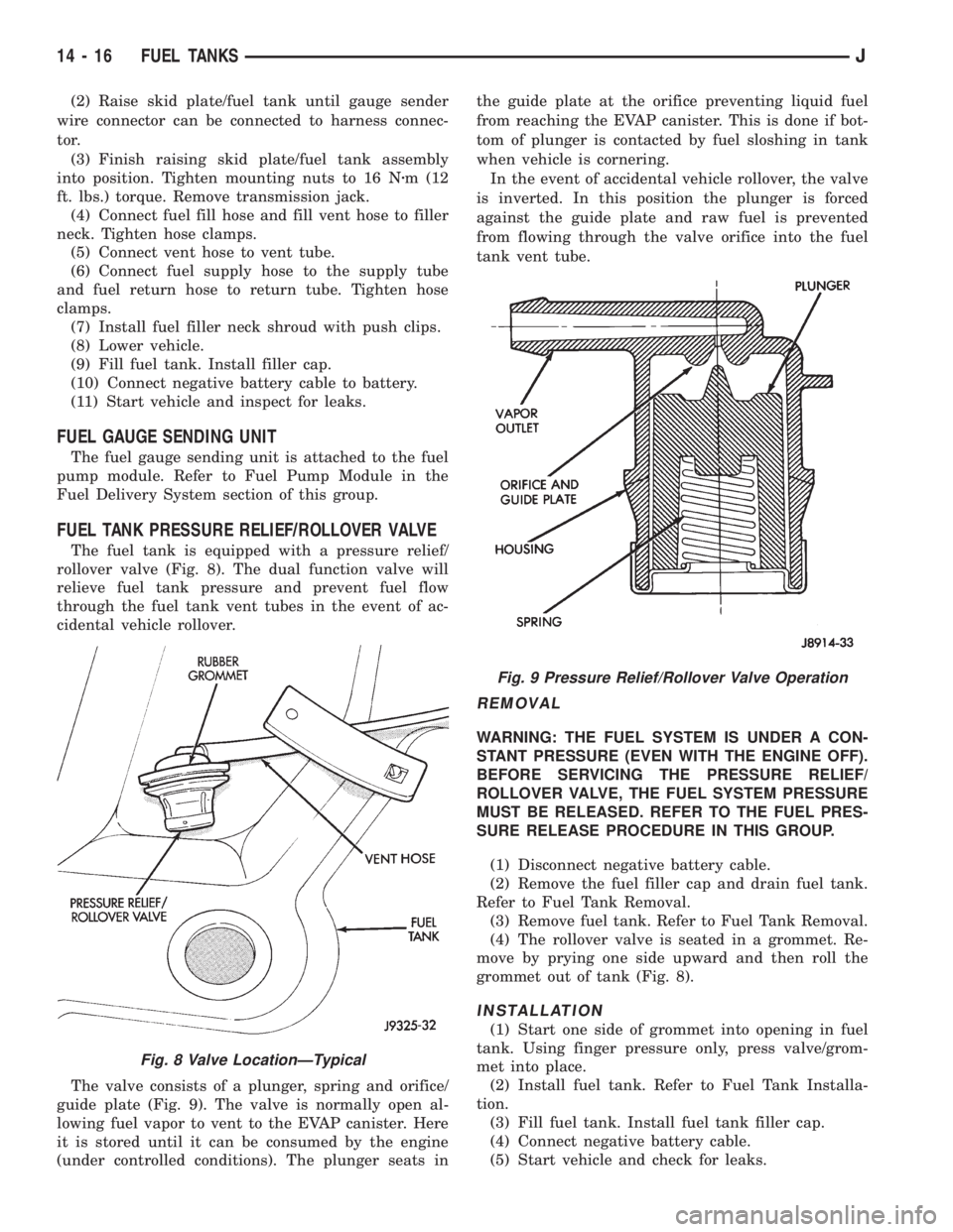
FUEL TANK PRESSURE RELIEF/ROLLOVER VALVE
The fuel tank is equipped with a pressure relief/
rollover valve (Fig. 8). The dual function valve will
relieve fuel tank pressure and prevent fuel flow
through the fuel tank vent tubes in the event of ac-
cidental vehicle rollover.
The valve consists of a plunger, spring and orifice/
guide plate (Fig. 9). The valve is normally open al-
lowing fuel vapor to vent to the EVAP canister. Here
it is stored until it can be consumed by the engine
(under controlled conditions). The plunger seats inthe guide plate at the orifice preventing liquid fuel
from reaching the EVAP canister. This is done if bot-
tom of plunger is contacted by fuel sloshing in tank
when vehicle is cornering.
In the event of accidental vehicle rollover, the valve
is inverted. In this position the plunger is forced
against the guide plate and raw fuel is prevented
from flowing through the valve orifice into the fuel
tank vent tube.
REMOVAL
WARNING: THE FUEL SYSTEM IS UNDER A CON-
STANT PRESSURE (EVEN WITH THE ENGINE OFF).
BEFORE SERVICING THE PRESSURE RELIEF/
ROLLOVER VALVE, THE FUEL SYSTEM PRESSURE
MUST BE RELEASED. REFER TO THE FUEL PRES-
SURE RELEASE PROCEDURE IN THIS GROUP.
(1) Disconnect negative battery cable.
(2) Remove the fuel filler cap and drain fuel tank.
Refer to Fuel Tank Removal.
(3) Remove fuel tank. Refer to Fuel Tank Removal.
(4) The rollover valve is seated in a grommet. Re-
move by prying one side upward and then roll the
grommet out of tank (Fig. 8).
INSTALLATION
(1) Start one side of grommet into opening in fuel
tank. Using finger pressure only, press valve/grom-
met into place.
(2) Install fuel tank. Refer to Fuel Tank Installa-
tion.
(3) Fill fuel tank. Install fuel tank filler cap.
(4) Connect negative battery cable.
(5) Start vehicle and check for leaks.
Fig. 8 Valve LocationÐTypical
Fig. 9 Pressure Relief/Rollover Valve Operation
14 - 16 FUEL TANKSJ
Page 1464 of 2158
FUEL RAIL ASSEMBLY
REMOVAL
WARNING: THE FUEL SYSTEM IS UNDER CON-
STANT FUEL PRESSURE (EVEN WITH THE ENGINE
OFF) OF APPROXIMATELY 131-269 KPA (19-39 PSI).
THIS PRESSURE MUST BE RELEASED BEFORE
SERVICING THE FUEL RAIL.
(1) Remove fuel tank filler tube cap.
(2) Disconnect the negative battery cable from bat-
tery.
(3) Perform the Fuel System Pressure Release Pro-
cedure as described in the Fuel Delivery System sec-
tion of this Group.
(4) Remove and numerically attach a tag (if fuel
injector is not already tagged), the injector harness
connectors. Do this at each injector (Fig. 12).
(5) Disconnect vacuum line from fuel pressure reg-
ulator (Fig. 12).
(6) Disconnect fuel supply line from fuel rail and
the fuel return line from fuel pressure regulator (Fig.
12). Refer to Fuel Tubes/Lines/Hoses and Clamps, or
Quick-Connect Fittings. These can both be found in
the Fuel Delivery section of this group.
(7) Remove fuel rail mounting bolts.
On models with automatic transmissions, it may be
necessary to remove automatic transmission throttle
line pressure cable and bracket. This will aid in fuel
rail assembly removal.
(8) Remove fuel rail by gently rocking until all the
fuel injectors are out of the intake manifold.
INSTALLATION
(1) Position tips of all fuel injectors into the corre-
sponding injector bore in the intake manifold. Seat
injectors into manifold.
(2) Tighten fuel rail mounting bolts to 27 Nzm (20
ft. lbs.) torque.
(3) Connect injector harness connectors to appro-
priate (tagged) injector.
(4) Connect both fuel lines to fuel rail. Refer to the
Fuel Delivery section of this group for procedures.
(5) Connect vacuum supply line to fuel pressure
regulator.
(6) Install protective cap to pressure test port fit-
ting.
(7) Install fuel tank cap.
(8) Connect negative battery cable to battery.
(9) Start engine and check for fuel leaks.
FUEL SYSTEM PRESSURE RELEASE PROCEDURE
WARNING: THE FUEL SYSTEM IS UNDER A CON-
STANT PRESSURE (EVEN WITH THE ENGINE OFF)
OF APPROXIMATELY 100 KPA (14.5 PSI). BEFORE
SERVICING THE FUEL PUMP, FUEL RAIL, FUELLINES, FUEL FILTER OR FUEL INJECTOR, THE
FUEL SYSTEM PRESSURE MUST BE RELEASED.
Refer to the Fuel Delivery System section of this
group. See Fuel Pressure Release procedure.
FUEL TANKS
Refer to the Fuel Tank section of this group for re-
moval/installation procedures.
FUEL TANK PRESSURE RELIEF/ROLLOVER VALVE
Refer to the Fuel Tank section of this group for re-
moval/installation procedures.
FUEL TUBES/LINES/HOSES AND CLAMPS
Refer to the Fuel Delivery System section of this
group for removal/installation procedures. Also refer
to Quick-Connect Fittings in the Fuel Delivery sec-
tion of this group.
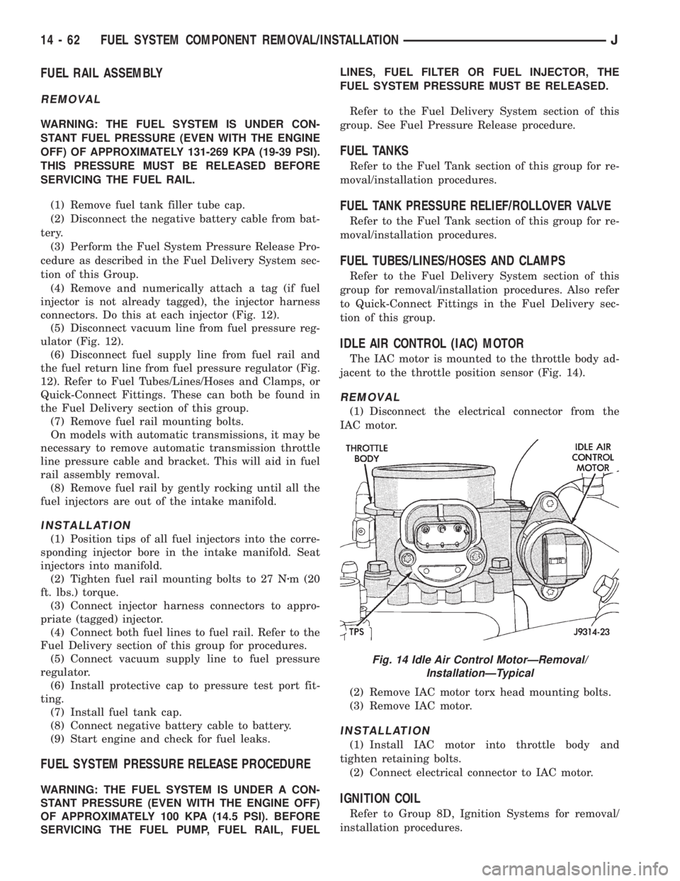
IDLE AIR CONTROL (IAC) MOTOR
The IAC motor is mounted to the throttle body ad-
jacent to the throttle position sensor (Fig. 14).
REMOVAL
(1) Disconnect the electrical connector from the
IAC motor.
(2) Remove IAC motor torx head mounting bolts.
(3) Remove IAC motor.
INSTALLATION
(1) Install IAC motor into throttle body and
tighten retaining bolts.
(2) Connect electrical connector to IAC motor.
IGNITION COIL
Refer to Group 8D, Ignition Systems for removal/
installation procedures.
Fig. 14 Idle Air Control MotorÐRemoval/
InstallationÐTypical
14 - 62 FUEL SYSTEM COMPONENT REMOVAL/INSTALLATIONJ
Page 2128 of 2158
BUMPERÐXJ, LIFTGATE LICENSE PLATE
SCREW ANCHOR.....................23-65
BUMPERÐXJ, REAR SEATBACK LATCH
STRIKER...........................23-84
BUMPERS......................13-16,13-5
BUS, CCD; FUEL/IGNITION (XJ).......8W-30-5
BUSHING AND PISTON CLEARANCE,
AW-4 .............................21-339
BUSHING REPLACEMENT, AXLE......2-12,2-34
BUSHING REPLACEMENT, LEAF SPRING
EYE; FRONT SUSPENSION AND AXLE.....2-17
BUSHING REPLACEMENT, LEAF SPRING
EYE; REAR SUSPENSION AND AXLES . . . 3-5,3-7
BUSHINGS, CLUTCH AND BRAKE PEDAL . . . 0-22
BUZZER, COMBINATION; INTERIOR
LIGHTING (YJ)....................8W-44-1
BUZZER MODULE.................8U-1,8U-2
BUZZER MODULE SCHEMATIC - YJ.......8U-4
CABLE, ACCELERATOR PEDAL AND
THROTTLE.....................14-17,14-58
CABLE ADJUSTMENT, PARK INTERLOCK . 21-195
CABLE ADJUSTMENT, SHIFT...........21-195
CABLE ADJUSTMENT, TRANSMISSION
THROTTLE.........................21-194
CABLE ADJUSTMENT, TRANSMISSION
THROTTLE VALVE....................21-71
CABLE ADJUSTMENT (XJ), PARK
INTERLOCK........................21-101
CABLE ADJUSTMENT (XJ), SHIFT.......21-100
CABLE ADJUSTMENT (XJ/YJ), THROTTLE
VALVE..............................21-101
CABLE REMOVE/INSTALL, SERVO.......8H-10
CABLE REPLACEMENT, TRANSMISSION
THROTTLE.........................21-193
CABLE REPLACEMENT (XJ), PARKING
BRAKE REAR.........................5-67
CABLE REPLACEMENT (YJ), PARKING
BRAKE FRONT........................5-67
CABLE REPLACEMENT (YJ), PARKING
BRAKE REAR.........................5-68
CABLE REPLACEMENTÐXJ, LATCH
RELEASE...........................23-11
CABLE RESISTANCE, SPARK PLUG......8D-14
CABLE, SERVO.......................8H-1
CABLE, SPEEDOMETER.................0-33
CABLE TENSIONER ADJUSTMENT
(XJ/YJ), PARKING BRAKE...............5-69
CABLE TENSIONER REPLACEMENT (XJ),
PARKING BRAKE......................5-66
CABLE, THROTTLE...................14-17
CABLE/LINKAGE ADJUSTMENT,
GEARSHIFT.........................21-71
CABLES, DISTRIBUTOR CAP AND
ROTOR, IGNITION.....................0-20
CABLES, SPARK PLUG SECONDARY.....8D-14,
8D-24
CABLES, VENT DOOR CONTROL.........24-32
CALIBRATION, COMPASS...............8C-5
CALIPER ASSEMBLY...................5-50
CALIPER CLEANING AND INSPECTION.....5-50
CALIPER DISASSEMBLY................5-48
CALIPER INSTALLATION................5-51
CALIPER OPERATION AND WEAR
COMPENSATION......................5-45
CALIPER REMOVAL....................5-48
CAMSHAFT......................9-32,9-74
CAMSHAFT PIN REPLACEMENT......9-34,9-75
CAMSHAFT POSITION SENSOR; FUEL
SYSTEM............................14-60
CAMSHAFT POSITION SENSOR;
FUEL/IGNITION (XJ)................8W-30-3
CAMSHAFT POSITION SENSOR;
FUEL/IGNITION (YJ)................8W-30-3
CAMSHAFT POSITION SENSOR;
IGNITION SYSTEMS..............8D-17,8D-2
CAMSHAFT POSITION SENSOR;
FUEL/IGNITION (XJ-RHD)............8W-30-3
CAMSHAFT POSITION SENSOR TEST;
FUEL SYSTEM.......................14-46
CAMSHAFT POSITION SENSOR TEST;
IGNITION SYSTEMS
...................8D-6
CAMSHAFT POSITION SENSORÐPCM
INPUT
.............................14-22
(CANADA ONLY)ÐXJ, DAYTIME
RUNNING LIGHTS
....................8L-15
(CANADA ONLY)ÐYJ, DAYTIME
RUNNING LIGHTS
....................8L-30
CANISTER, EVAP
..................25-4,25-7CAP AND ROTOR, IGNITION CABLES,
DISTRIBUTOR........................0-20
CAP, DISTRIBUTOR....................8D-7
CAP, FUEL TANK FILLER TUBE;
EMISSION CONTROL SYSTEMS......25-4,25-7
CAP, FUEL TANK FILLER TUBE; FUEL
SYSTEM............................14-13
CAP, RADIATOR PRESSURE.............7-25
CAPACITIES, COOLING SYSTEM..........7-45
CAPACITIES, FLUID.....................0-3
CAPACITIES, FUEL TANK..........14-13,14-67
CAPACITY TEST, FUEL PUMP............14-7
CAR REPLACEMENT, PITMAN SHAFT
SEALSÐIN.........................19-23
CARDAN (CV), DOUBLE................16-11
CARDAN, SINGLE....................16-10
CARGO BARRIERÐXJ................23-101
CARGO LAMP AND DOME LAMP;
INTERIOR LIGHTING (XJ-RHD)........8W-44-1
CARGO LAMP, COURTESY LAMPS AND
DOME LAMP; INTERIOR LIGHTING (XJ) . 8W-44-1
CARGO LAMPÐXJ...................23-94
CARPET/MATÐXJ, FRONT.............23-99
CARPET/MATÐXJ, REAR.............23-100
CARPETÐYJ.......................23-156
CARPETS AND FLOOR MATSÐXJ.......23-99
CARRIERÐYJ, EXTERNAL SPARE/
WHEEL TIRE.......................23-133
CASE (4WD VEHICLES), TRANSFER........0-24
CASE ASSEMBLY, TRANSFER....21-294,21-319
CASE CHANGES, TRANSFER...........21-307
CASE CLEANING AND INSPECTION,
TRANSMISSION.....................21-125
CASE COVER OIL SEAL REPLACEMENT,
TIMING.........................9-30,9-73
CASE COVER, TIMING..............9-31,9-72
CASE DISASSEMBLY AND OVERHAUL,
TRANSFER...................21-289,21-310
CASE IDENTIFICATION, TRANSFER.....21-284,
21-307
CASE INSTALLATION, TRANSFER . 21-288,21-309
CASE LUBRICANT AND FILL LEVEL,
TRANSFER.........................21-284
CASE, NP231 TRANSFER.......21-283,21-305
CASE, NP242 TRANSFER.......21-307,21-331
CASE OVERHAUL, FIRST-REVERSE
BRAKE PISTON AND TRANSMISSION....21-247
CASE REMOVAL, TRANSFER.....21-287,21-309
CASE SKID PLATE, TRANSFER......13-15,13-3
CASE SPECIFICATIONS, TRANSMISSION/
TRANSFER.........................21-333
CATALYTIC CONVERTER............11-1,11-4
CATALYTIC CONVERTOR................25-1
CAUTIONS, AND WARNINGS, NOTES;
WIRING DIAGRAMSÐGENERAL
INFORMATION (XJ)...................8W-1
CCD BUS; FUEL/IGNITION (XJ)........8W-30-5
CENTER HIGH MOUNTED STOP LAMP
(CHMSL)ÐXJ.......................8L-12
CENTER HIGH MOUNTED STOP LAMP
(CHMSL)ÐYJ.......................8L-28
CERTIFICATION LABEL, VEHICLE SAFETY . Intro.-4
CHAIN AND SPROCKETS, TIMING....9-31,9-73
CHANGE AND FILTER REPLACEMENT,
ENGINE OIL
..........................0-16
CHANGE, LUBRICANT; FRONT
SUSPENSION AND AXLE
................2-23
CHANGE, LUBRICANT; REAR
SUSPENSION AND AXLES
...........3-13,3-31
CHANGE, REFILLING AFTER OVERHAUL
OR FLUID/FILTER
..............21-100,21-182
CHANGES AND PARTS
INTERCHANGEABILITY, TRANSMISSION
. . . 21-67
CHANGES, TRANSFER CASE
...........21-307
CHANNEL REPLACEMENTÐYJ, DOOR
FRAME GLASS
......................23-142
CHARGING, BATTERY
..................8A-7
CHARGING REFRIGERANT SYSTEM
......24-11
CHARGING SYSTEM; BATTERY/
STARTING/CHARGING SYSTEMS
DIAGNOSTICS
.......................8A-17
CHARGING SYSTEM; CHARGING
SYSTEM (XJ)
.....................8W-20-1
CHARGING SYSTEM; CHARGING
SYSTEM (XJ-RHD)
.................8W-20-1
CHARGING SYSTEM; CHARGING
SYSTEM (YJ)
.....................8W-20-1CHARGING SYSTEM INDICATOR LAMP;
INSTRUMENT CLUSTER (XJ).........8W-40-3
CHARGING SYSTEM SPECIFICATIONS....8A-23
CHARGING TIME TABLE, BATTERY........8A-8
CHART, MAIN BEARING FITTING......9-48,9-90
CHART, XJ PERFORMANCE
TEMPERATURE AND PRESSURE.........24-13
CHART, YJ PERFORMANCE
TEMPERATURE AND PRESSURE.........24-13
CHARTÐAX 15 MANUAL
TRANSMISSION, SELECTIVE SNAP
RING.............................21-334
CHARTS, BRAKELINE..................5-12
CHARTS, DIAGNOSIS GUIDES...........21-77
CHARTS, GEARTRAIN OPERATION AND
APPLICATION.......................21-169
CHARTS, INSPECTION AND DIAGNOSIS.....6-4
CHASSIS AND BODY COMPONENTS.......0-28
CHASSIS COMPONENT AND WHEEL
BEARING LUBRICANTS.................0-28
CHECK VALVE TEST, POWER BOOSTER.....5-9
CHECKING FLUID LEVEL AND
CONDITION........................21-182
CHECKS, PRELIMINARY.................7-5
CHIME/BUZZER MODULE; INTERIOR
LIGHTING (XJ)....................8W-44-2
CHIME/BUZZER MODULE; INTERIOR
LIGHTING (XJ-RHD)................8W-44-2
CHMSL LAMPS, STOP LAMPS; REAR
LIGHTING (XJ)....................8W-51-1
CHMSL LAMPS, STOP LAMPS; REAR
LIGHTING (XJ-RHD)................8W-51-1
CHMSL LAMPS, STOP LAMPS; REAR
LIGHTING (YJ)....................8W-51-1
(CHMSL)ÐXJ, CENTER HIGH MOUNTED
STOP LAMP.........................8L-12
(CHMSL)ÐYJ, CENTER HIGH MOUNTED
STOP LAMP.........................8L-28
CIGAR LIGHTER; HORN/CIGAR LIGHTER . . . 8E-1
CIGAR LIGHTER; HORN/CIGAR LIGHTER
(YJ).............................8W-41-1
CIGAR LIGHTER; INSTRUMENT CLUSTER
(XJ).............................8W-40-1
CIRCUIT IDENTIFICATION; WIRING
DIAGRAMSÐGENERAL INFORMATION
(XJ)...............................8W-1
CIRCUIT REMOVE/INSTALL, PRINTED....8E-19,
8E-40
CIRCUIT SENSEÐPCM INPUT, IGNITION . . 14-23
CIRCUIT VOLTAGE, OPEN...............8A-6
CLAMPS, FUEL TUBES/LINES/HOSES . 14-62,14-9
CLASSIFICATION OF LUBRICANTS.........0-2
CLASSIFICATIONS AND RATINGS,
BATTERY...........................8A-23
CLEANER, AIR.......................14-29
CLEANER ELEMENT, AIR; EMISSION
CONTROL SYSTEMS...................25-7
CLEANER ELEMENT, AIR; FUEL SYSTEM . . 14-59
CLEANER ELEMENT, AIR; LUBRICATION
AND MAINTENANCE...................0-18
CLEANER HOUSING, AIR...............14-58
CLEANING AND INSPECTION, CALIPER....5-50
CLEANING AND INSPECTION, GEAR......19-42
CLEANING AND INSPECTION,
TRANSMISSION CASE................21-125
CLEANING OF TIRES...................22-2
CLEANING/INSPECTION; FRONT
SUSPENSION AND AXLE
................2-37
CLEANING/INSPECTION; REAR
SUSPENSION AND AXLES
...............3-20
CLEANING/REVERSE FLUSHING,
COOLING SYSTEM
....................7-22
CLEARANCE AND RAMP ANGLE,
GROUND
............................0-11
CLEARANCE, AW-4 BUSHING AND
PISTON
...........................21-339
CLOCKSPRING
.......................19-51
CLUSTER AND GAUGE HOUSINGSÐYJ,
INSTRUMENT
......................23-151
CLUSTER ASSEMBLY REMOVE/INSTALL
. . 8E-17,
8E-35
CLUSTER BEZELÐXJ, INSTRUMENT
.....23-80
CLUSTER BEZELÐYJ, INSTRUMENT
....23-151
CLUSTER CONNECTORS (RHD)
.........8E-11
CLUSTER, GAUGE PACKAGE
.......8E-31,8E-43
CLUSTER GROUND; INSTRUMENT
CLUSTER (XJ)
.....................8W-40-3
4 INDEXJ
Description Group-Page Description Group-Page Description Group-Page
Page 2132 of 2158
DIAGRAM INDEX; AIR CONDITIONING/
HEATER (XJ-RHD)..................8W-42-2
DIAGRAM INDEX; AIR CONDITIONING/
HEATER (YJ)...............8W-42-1,8W-42-2
DIAGRAM INDEX; ANTI-LOCK BRAKES
(XJ).............................8W-32-3
DIAGRAM INDEX; ANTI-LOCK BRAKES
(XJ-RHD).........................8W-32-3
DIAGRAM INDEX; ANTI-LOCK BRAKES
(YJ).............................8W-32-2
DIAGRAM INDEX; CHARGING SYSTEM
(XJ).............................8W-20-1
DIAGRAM INDEX; CHARGING SYSTEM
(XJ-RHD).........................8W-20-1
DIAGRAM INDEX; CHARGING SYSTEM
(YJ).............................8W-20-1
DIAGRAM INDEX; FRONT LIGHTING (XJ) . 8W-50-2
DIAGRAM INDEX; FRONT LIGHTING
(XJ-RHD).........................8W-50-3
DIAGRAM INDEX; FRONT LIGHTING (YJ) . 8W-50-2
DIAGRAM INDEX; FUEL/IGNITION (YJ) . . 8W-30-5
DIAGRAM INDEX; FUSE/FUSE BLOCK
(XJ).............................8W-10-1
DIAGRAM INDEX; FUSE/FUSE BLOCK
(XJ-RHD).........................8W-10-1
DIAGRAM INDEX; FUSE/FUSE BLOCK
(YJ).............................8W-10-1
DIAGRAM INDEX; GROUND
DISTRIBUTION (XJ)................8W-15-1
DIAGRAM INDEX; GROUND
DISTRIBUTION (XJ-RHD)............8W-15-1
DIAGRAM INDEX; GROUND
DISTRIBUTION (YJ)..................8W-15-1
DIAGRAM INDEX; HEATED REAR
WINDOW (XJ).....................8W-48-1
DIAGRAM INDEX; HEATED REAR
WINDOW (XJ-RHD).................8W-48-1
DIAGRAM INDEX; HEATED REAR
WINDOW (YJ).....................8W-48-1
DIAGRAM INDEX; HORN/CIGAR LIGHTER . . . 8E-1
DIAGRAM INDEX; HORN/CIGAR LIGHTER
(YJ).............................8W-41-1
DIAGRAM INDEX; INSTRUMENT
CLUSTER (XJ).............8W-40-1,8W-40-3
DIAGRAM INDEX; INSTRUMENT
CLUSTER (XJ-RHD)................8W-40-3
DIAGRAM INDEX; INSTRUMENT
CLUSTER (YJ).....................8W-40-2
DIAGRAM INDEX; INTERIOR LIGHTING
(XJ).............................8W-44-2
DIAGRAM INDEX; INTERIOR LIGHTING
(XJ-RHD).........................8W-44-2
DIAGRAM INDEX; INTERIOR LIGHTING
(YJ).............................8W-44-2
DIAGRAM INDEX; OVERHEAD CONSOLE
(XJ).............................8W-49-1
DIAGRAM INDEX; OVERHEAD CONSOLE
(XJ-RHD).........................8W-49-1
DIAGRAM INDEX; POWER DISTRIBUTION
(XJ).............................8W-11-1
DIAGRAM INDEX; POWER DISTRIBUTION
(XJ-RHD).........................8W-11-1
DIAGRAM INDEX; POWER DISTRIBUTION
(YJ).............................8W-11-1
DIAGRAM INDEX; POWER DOOR LOCKS
(XJ)
.............................8W-61-1
DIAGRAM INDEX; POWER DOOR LOCKS
(XJ-RHD)
.........................8W-61-1
DIAGRAM INDEX; POWER MIRRORS
(XJ)
.............................8W-62-1
DIAGRAM INDEX; POWER MIRRORS
(XJ-RHD)
.........................8W-62-1
DIAGRAM INDEX; POWER SEAT (XJ)
. . . 8W-63-1
DIAGRAM INDEX; POWER SEAT
(XJ-RHD)
.........................8W-63-1
DIAGRAM INDEX; POWER WINDOWS
(XJ)
.............................8W-60-2
DIAGRAM INDEX; POWER WINDOWS
(XJ-RHD)
.........................8W-60-2
DIAGRAM INDEX; REAR LIGHTING (XJ)
. 8W-51-1
DIAGRAM INDEX; REAR LIGHTING
(XJ-RHD)
.........................8W-51-1
DIAGRAM INDEX; REAR LIGHTING (YJ)
. 8W-51-1
DIAGRAM INDEX; STARTING SYSTEM
(XJ)
.............................8W-21-1
DIAGRAM INDEX; STARTING SYSTEM
(XJ-RHD)
.........................8W-21-1DIAGRAM INDEX; STARTING SYSTEM
(YJ).............................8W-21-1
DIAGRAM INDEX; TRAILER TOW (XJ) . . 8W-54-1
DIAGRAM INDEX; TRAILER TOW
(XJ-RHD).........................8W-54-1
DIAGRAM INDEX; TRANSMISSION
CONTROLS (XJ)...................8W-31-1
DIAGRAM INDEX; TRANSMISSION
CONTROLS (XJ-RHD)...............8W-31-1
DIAGRAM INDEX; TRANSMISSION
CONTROLS (YJ)...................8W-31-1
DIAGRAM INDEX; TURN SIGNALS (XJ) . 8W-52-1
DIAGRAM INDEX; TURN SIGNALS
(XJ-RHD).........................8W-52-1
DIAGRAM INDEX; TURN SIGNALS (YJ) . 8W-52-1
DIAGRAM INDEX; VEHICLE SPEED
CONTROL (XJ)....................8W-33-1
DIAGRAM INDEX; VEHICLE SPEED
CONTROL (XJ-RHD)................8W-33-1
DIAGRAM INDEX; WIPERS (XJ).......8W-53-2
DIAGRAM INDEX; WIPERS (XJ-RHD) . . . 8W-53-2
DIAGRAM INDEX; WIPERS (YJ).......8W-53-2
DIAGRAM INDEX; FUEL/IGNITION
(XJ-RHD).........................8W-30-5
DIAGRAM INDEXÐ2.5L ENGINE;
FUEL/IGNITION (XJ)................8W-30-6
DIAGRAM INDEXÐ4.0L ENGINE;
FUEL/IGNITION (XJ)................8W-30-6
DIFFERENTIAL AND PINION
MEASUREMENT.......................2-40
DIFFERENTIAL ASSEMBLY; FRONT
SUSPENSION AND AXLE.................2-38
DIFFERENTIAL ASSEMBLY; REAR
SUSPENSION AND AXLES...............3-21
DIFFERENTIAL DISASSEMBLY; FRONT
SUSPENSION AND AXLE................2-35
DIFFERENTIAL DISASSEMBLY; REAR
SUSPENSION AND AXLES...............3-18
DIFFERENTIAL INSTALLATION............2-44
DIFFERENTIAL, LIMITED SLIP............3-10
DIFFERENTIAL MEASUREMENT AND
INSTALLATION........................3-25
DIFFERENTIAL OVERHAUL..............3-46
DIFFERENTIAL REMOVAL; FRONT
SUSPENSION AND AXLE................2-34
DIFFERENTIAL REMOVAL; REAR
SUSPENSION AND AXLES...............3-18
DIFFERENTIAL SERVICE................3-34
DIFFERENTIAL SHIM PACK
MEASUREMENT AND ADJUSTMENT.......2-43
DIFFERENTIAL, TRAC-LOK..............3-45
DIMENSION DATA, VEHICLE.....Intro.-5,Intro.-6
DIMENSIONS, AW-4 VALVE BODY CHECK
BALL.............................21-341
DIMENSIONS, DESIGNATIONS,
LABELS/PLATES, CODES..............Intro.-1
DIMENSIONS, FRAME.............13-13,13-1
DIMMER SWITCH REMOVE/INSTALL,
HEADLAMP OR PANEL................8E-42
DIMMER SWITCH REPLACEMENTÐYJ,
HEADLAMP.........................8L-26
DIMMING MODULE; FRONT LIGHTING
(XJ-RHD).........................8W-50-1
DIODE REPLACEMENT; WIRING
DIAGRAMSÐGENERAL INFORMATION
(XJ)...............................8W-8
DIRECT CLUTCH OVERHAUL...........21-228
DISASSEMBLY AND INSPECTION, VALVE
BODY.............................21-147
DISASSEMBLY AND OVERHAUL,
TRANSFER CASE..............21-289,21-310
DISASSEMBLY AND OVERHAUL,
TRANSMISSION.................21-37,21-5
DISASSEMBLY, CALIPER................5-48
DISASSEMBLY, DIFFERENTIAL; FRONT
SUSPENSION AND AXLE................2-35
DISASSEMBLY, DIFFERENTIAL; REAR
SUSPENSION AND AXLES...............3-18
DISASSEMBLY, TRANSMISSION . . 21-119,21-201
DISASSEMBLYÐCOLUMN OR CONSOLE
SHIFT..............................19-60
DISC AND PLATE THICKNESS, AW-4
CLUTCH...........................21-338
DISC BRAKE ROTOR REFINISHING
........5-53
DISC BRAKE ROTOR RUNOUT
...........5-52
DISC BRAKE ROTOR THICKNESS
.........5-52
DISC BRAKES
........................5-45
DISC BRAKESHOE INSTALLATION
.........5-47DISC BRAKESHOE REMOVAL............5-46
DISC INSTALLATION, CLUTCH COVER.....6-10
DISC REMOVAL, CLUTCH COVER.........6-10
DISC RUNOUT, CLUTCH COVER...........6-3
DISCHARGE (ESD) SENSITIVE DEVICES,
ELECTROSTATIC; WIRING
DIAGRAMSÐGENERAL INFORMATION
(XJ)...............................8W-2
DISCONNECT AXLEÐYJ VEHICLES,
VACUUM............................2-27
DISCONNECT AXLE/SHIFT MOTOR
DIAGNOSIS..........................2-29
DISCONNECT AXLE/SHIFT MOTOR
DIAGNOSIS (CONT'D)..................2-30
DISPLAY, ABS WARNING LIGHT...........5-3
DISPLAY SYMBOLS, INTERNATIONAL
VEHICLE CONTROL..................Intro.-5
DISPLAY SYMBOLS, VEHICLE CONTROL . Intro.-10
DISPOSALÐXJ, LIFTGATE SUPPORT
ROD CYLINDER......................23-63
DISTRIBUTOR.......................8D-19
DISTRIBUTOR CAP....................8D-7
DISTRIBUTOR CAP AND ROTOR,
IGNITION CABLES.....................0-20
DISTRIBUTOR ROTOR.................8D-8
DISTRIBUTORS.......................8D-4
DOME LAMP, CARGO LAMP; INTERIOR
LIGHTING (XJ-RHD)................8W-44-1
DOME LAMP, CARGO LAMP, COURTESY
LAMPS; INTERIOR LIGHTING (XJ).....8W-44-1
DOME LAMP REPLACEMENTÐXJ.........8L-17
DOME LAMPÐXJ....................23-93
DOME LAMPS, COURTESY LAMPS;
INTERIOR LIGHTING (YJ)............8W-44-1
DOME/CARGO LAMP BULB
REPLACEMENTÐYJ VEHICLES,
HARDTOP..........................8L-31
DOME/COURTESY LAMP SERVICE
INFORMATIONÐXJ...................8L-16
DOME/COURTESY LAMP SERVICE
INFORMATIONÐYJ...................8L-31
DOME/COURTESY LAMP TROUBLE
DIAGNOSISÐXJ.....................8L-16
DOME/COURTESY LAMP TROUBLE
DIAGNOSISÐYJ.....................8L-31
DOOR ALIGNMENT ADJUSTMENTÐ
MAJOR............................23-41
DOOR ALIGNMENT ADJUSTMENTÐ
MINOR.............................23-37
DOOR ASSIST HANDLEÐYJ, FULL-
METAL............................23-136
DOOR BUMPERSÐXJ, FUEL FILLER.....23-27
DOOR CONTROL CABLES, VENT.........24-32
DOOR EDGE GUARD/EDGE PROTECTOR
STRIPÐXJ.........................23-54
DOOR EXTERNAL HANDLEÐXJ.........23-48
DOOR FRAME GLASS CHANNEL
REPLACEMENTÐYJ.................23-142
DOOR HINGE/HINGE PIN
REPLACEMENTÐXJ..................23-52
DOOR HINGESÐYJ, FULL-METAL.......23-140
DOOR INSIDE LATCH RELEASE AND
LOCK RODSÐXJ.....................23-50
DOOR JAMB SWITCH, DRIVER'S.....8U-1,8U-2
DOOR KEY LOCK CYLINDERÐXJ........23-47
DOOR KEY LOCK CYLINDERÐYJ,
FULL-METAL.......................23-139
DOOR LATCH ADJUSTMENTÐXJ........23-48
DOOR LATCH EXTERNAL RELEASE
HANDLEÐYJ, FULL-METAL............23-140
DOOR LATCH INSIDE RELEASE AND
LOCK HANDLEÐYJ, FULL-METAL.......23-137
DOOR LATCH STRIKERÐYJ, HALF-
METAL............................23-135
DOOR LATCHÐXJ....................23-49
DOOR LATCHÐYJ, FULL-METAL........23-140
DOOR LOCKS, POWER; POWER DOOR
LOCKS (XJ).......................8W-61-1
DOOR LOCKS, POWER; POWER DOOR
LOCKS (XJ-RHD)
..................8W-61-1
DOOR MIRROR (EXTERNAL)ÐYJ, HALF
METAL
............................23-121
DOOR MOTOR SWITCH REPLACEMENT,
BLOWER MOTOR/AIR
.................24-32
DOOR OPENER STORAGE, REMOTE
GARAGE
............................8C-1
DOOR OPENING WEATHERSTRIP
SEALSÐXJ, DOOR WINDOW GLASS
.....23-55
8 INDEXJ
Description Group-Page Description Group-Page Description Group-Page